


-
Magnetic field sensing plays a pivotal role in numerous fields such as medicine, transportation, and aerospace1-3. Among the various types of magnetic field sensors that have been developed4-7, optical fiber-based sensors possess outstanding characteristics such as compactness, long-distance interrogation, low cost, and high sensitivity, thus attracting significant interest8-14. In recent years, various optical fibers integrated with magnetic functional materials have been extensively investigated for performance optimization. Typically, side-polished fibers8, tapered fibers9, photonic crystal fibers10-12, fiber Mach-Zender interferometers (MZIs)13, and fiber Fabry-Perot interferometers (FPIs)14, can be used to detect the magnetic field when incorporated with magnetic fluids (MFs). In particular, the sensitivity of the side-polished fibers filled with MFs has reached 2370 pm/mT8. However, a sensor based on the magneto-optical effect of MFs may be affected by temperature perturbation. In addition, the packaging of fluids leads to bulky implementations that require laborious operations. Temperature crosstalk can be effectively eliminated by integrating multiple sensing elements12, at the expense of increasing the size of the entire sensing component; however, the different spatial locations of multiple elements can cause measurement errors in multi-parameter discriminative sensing.
Two-photon polymerization (TPP), a 3D printing technique with high fabrication accuracy and flexibility, can effectively fabricate micro/nanostructures on an optical fiber platform, achieving superior results in realizing complex high-performance optical, mechanical, and biological structures. A variety of fiber-tip devices such as microcantilevers15-19 and clamped-beam probes20 have been implemented on the fiber tip, using the TPP technique for hydrogen, nanoforce, magnetic field, and biosensing applications. However, 3D printed fiber-tip devices are generally implemented based on an ordinary single-core fiber; and the manufactured tip element is based on a single channel, making it difficult to integrate functional multi-elements. A multicore fiber (MCF) contains multiple optical transmission channels in a single fiber, providing the advantages of high integration and space division multiplexing. We implemented an MCF-tip temperature and humidity discriminative sensor by fabricating dual microtips21; however, the polymer self-growing fabrication method cannot customize different structural patterns without restraint. The TPP 3D printing technique can efficiently fabricate multiple customized sensing elements on the end facet of MCF based on various application scenarios, making it widely utilizable in ultracompact MCF-tip devices with an exquisite structure incorporating functional materials.
In this study, we propose, design, and experimentally demonstrate ultracompact MCF-tip probes for magnetic-field and temperature-discriminative sensing (Fig. 1). Using the TPP technique, a bowl-shaped microcantilever and microfluid-infiltrated microcavity were printed on two different cores of an MCF, acting as two miniaturized FPIs. An iron ball was incorporated inside the bowl-shaped tip of the microcantilever to render it magnetically sensitive, and the microfluid-infiltrated microcavity acted as a highly sensitive temperature-sensing element. Discriminative measurements of the two parameters can be realized using a sensitivity coefficient matrix. By attaching an iron ball into a 3D-printed bowl of the microcantilever with 2 μm thickness, a high magnetic field intensity sensitivity of 1805.6 pm/mT with a fast response time of ~ 213 ms was obtained. The microfluid-infiltrated microcavity exhibited a high temperature sensitivity of 160.3 pm/℃ in the range of 25℃ to 55℃. The condition number of the sensor was as low as 11.28, indicating that the sensor has high reliability in the discriminative measurement of the magnetic field and temperature. The spatial location accuracy in discriminative measurements was significant due to the highly integrated sensing components on the MCF-tip with core-to-core spacing of 50 μm. The proposed 3D printed MCF-tip probes have the capability to detect multiple signals on a tiny fiber tip through multiple channels within a single fiber, providing an ultracompact, sensitive, and reliable scheme for discriminative measurements when the sensing space is extremely limited, as in medical, transportation, and aerospace applications.
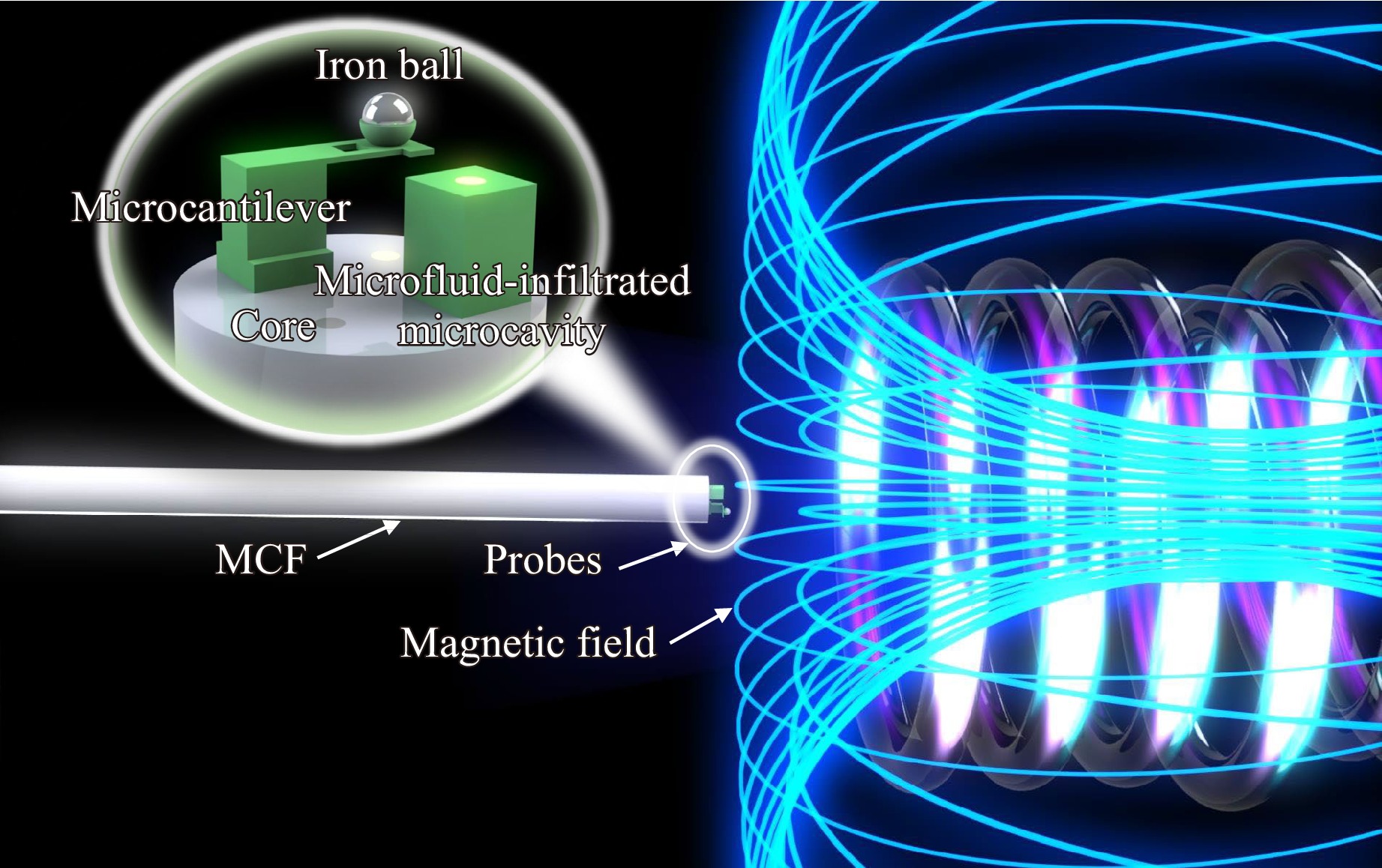
Fig. 1 Schematic diagram of the MCF-tip probes for magnetic field and temperature discriminative sensing.
-
The principle of the MCF-tip dual FPIs for discriminative measurement of the magnetic field and temperature is shown in Fig. 2. A polymer microcantilever and microfluid-infiltrated microcavity are printed on the end facet of the MCF to reflect the light emerging from the two different cores. Light from the fiber core is partially reflected back to the fiber core under the action of Mirror-1. The transmitted light is then partially reflected by Mirror-2 and collected by the fiber core. Thus, when the two beams of reflected light with a phase difference meet in the fiber core, they generate an interference resonance. The reflected light intensity of the two-beam interference in the fiber FPI is expressed as22,
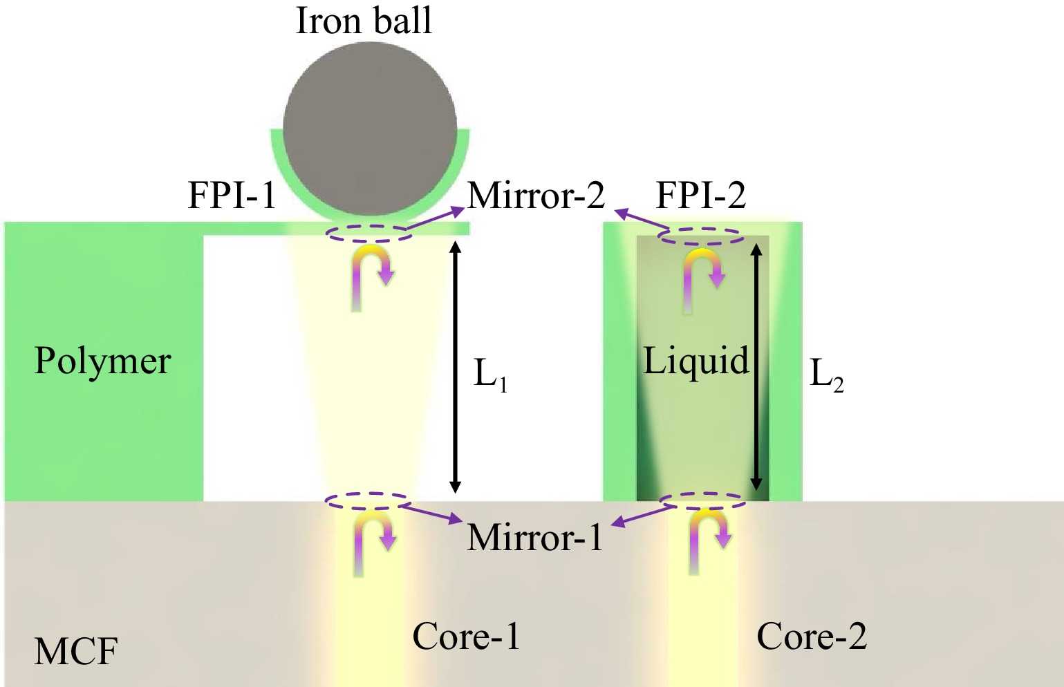
Fig. 2 Principle of FPIs with dual-tip MCF for discriminative measurement of magnetic field and temperature.
$$ \begin{split} {I_R} =\;& {I_0}[{R_1} + {R_2}\eta - 2\sqrt {{R_1}{R_2}\eta } \cos (\Delta \delta + {\delta _0})] \\ \propto\;& {I_0}[1 - \gamma \cos (\Delta \delta + {\delta _0})] \end{split} $$ (1) where $ {I_R} $ is the intensity of the interference light; $ {I_0} $ is the intensity of the light discharged into the FPI; $ {R_1} $ and $ {R_2} $ are the reflectivities of the two mirrors; $ \eta $ is the transmission coefficient of the FP cavity; $ \Delta \delta $ is the phase difference between the two beams of light; $ {\delta _0} $ is the initial phase of the incident light; and $ \gamma $ is the extinction ratio of the reflection spectrum. Here, the phase difference can be written as:
$$ \Delta \delta = \frac{{2{\text π} }}{\lambda }\Delta Q = \frac{{2{\text π} }}{\lambda }2nL $$ (2) where $ \lambda $ is the wavelength; $ \Delta Q $ is the optical path difference (OPD) between the two light beams; $ n $ is the effective refractive index (RI) of the medium in the FP cavity; and L is the cavity length. Variations in $ n $ and L can lead to variations in OPD, which is represented by a spectral shift of the FPI interference resonance wavelength.
In FPI-1, Mirror-1 is the interface between the fiber end facet and air, and Mirror-2 is the interface between air and the polymer microcantilever. A magnetic field can cause the microcantilever to deform when incorporated into the iron ball. The variation in the deflection of the microcantilever is equivalent to the variation in the cavity length of FPI-1. The relationship between the magnetic force F (kN) acting on the microcantilever and deflection $ \Delta L $ (mm) can be described as20,
$$ \Delta L = \frac{{F{L^3}}}{{3EI}} $$ (3) where L (mm) is the microcantilever length; E (GPa) is Young’s modulus of the polymer; and I is the second moment of the area of the microcantilever. In the experiments, the printed microcantilever was rectangular, and the second moment of the area $ {I_{re}} $ was calculated as20,
$$ {I_{re}} = \frac{{b{h^3}}}{{12}} $$ (4) where $ b $ (mm) and $ h $ (mm) are the width and thickness of the microcantilever, respectively.
The magnetic force F attracting the iron ball can be calculated using the “effective” dipole moment method in which the magnetized particle is replaced by an “equivalent” point dipole with a moment. Briefly, the F acting on the dipole is calculated as23,
$$ F = {\mu _0}V{\text{(}}M \cdot \nabla {\text{)}}H $$ (5) where $ {\mu _0} $ is the permeability of free space; V is the volume of the iron ball; M is the magnetization of the iron ball; and H is the intensity of the magnetic field. Because the measured magnetic field intensity was between 30-90 mT in our experiment, which is far less than the magnetic field intensity when pure iron has a saturated magnetization24, the unsaturated magnetization of the iron ball can be expressed as23,
$$ M{\text{ = }}\frac{{3\chi }}{{\chi + 3}}H $$ (6) where $ \chi $ denotes the susceptibility of the iron balls. In this case, Eq. 5 can finally be written as25,
$$ F = {\mu _0}V\frac{{3\chi }}{{\chi + 3}}H\frac{{\partial H}}{{\partial x}} $$ (7) where $ {{\partial H}}/{{\partial x}} $ is the magnetic field gradient. Therefore, the deflection of the microcantilever can be demodulated by monitoring the shift in the traced dip wavelength. The force acting on the microcantilever can be calculated using Eq. 3, which is consistent with the magnetic force acting on the iron ball calculated by Eq. 7.
In FPI-2, Mirror-1 and Mirror-2 are the upper and lower interfaces of the microfluid-infiltrated microcavity, respectively. Similarly, variations in the volume and RI of the microfluid-infiltrated cavity with temperature can cause a shift in the FPI-2 interference resonance wavelength. The two FPIs with different properties can obtain different spectral shifts in terms of magnetic field intensity and temperature variations. Therefore, the wavelength shifts of FPI-1 ($ \Delta {\lambda }_{1} $) and FPI-2 ($ \Delta {\lambda }_{2} $) can be characterized by the sensitivity coefficient matrix of the two-parameter two-equation system21:
$$ \left[ \begin{array}{*{20}{c}} \Delta {\lambda _1} \\ \Delta {\lambda _2} \\ \end{array} \right] = \left[\begin{array}{*{20}{c}} S_1^H & S_1^T\\ S_2^H & S_2^T \end{array} \right] \left[\begin{array}{*{20}{c}} \Delta H \\ \Delta T \end{array} \right] $$ (8) where $ \Delta H $ is the variation in magnetic field intensity; $ \Delta T $ is the variation of temperature; $ S_{1,2}^H $ and $ S_{1,2}^T $ are the sensitivity coefficients of magnetic field intensity and temperature of FPI-1 and FPI-2, respectively. Thus, the magnetic field intensity and temperature encoded in the cavity length or RI of the medium can be extracted by tracking the shift in the interference resonance wavelength.
-
The MCF-tip probe fabrication process is shown in Fig. 3. Prior to polymerization, the microcantilever and microfluid-infiltrated microcavity were 3D modeled according to design, considering the characteristics of the models in planning fabrication parameters such as slicing, line spacing, and scanning path (Fig. 3a). A bowl-shaped structure was added to the top of the polymer microcantilever to carry the iron ball. The microcavity on another core end facet solidifies the surface profile during polymerization, allowing the microfluid polymer to be enclosed in the microcavity26. To balance fabrication quality and efficiency, slicing and line spacings were optimized to 500 nm and 300 nm, respectively, and an S-shaped scanning path was adopted. A 3D laser lithography system for micro/nanofabrication (Nanoscribe GmbH)27,28 was used to print the microcantilever and microcavity onto the MCF end facet.
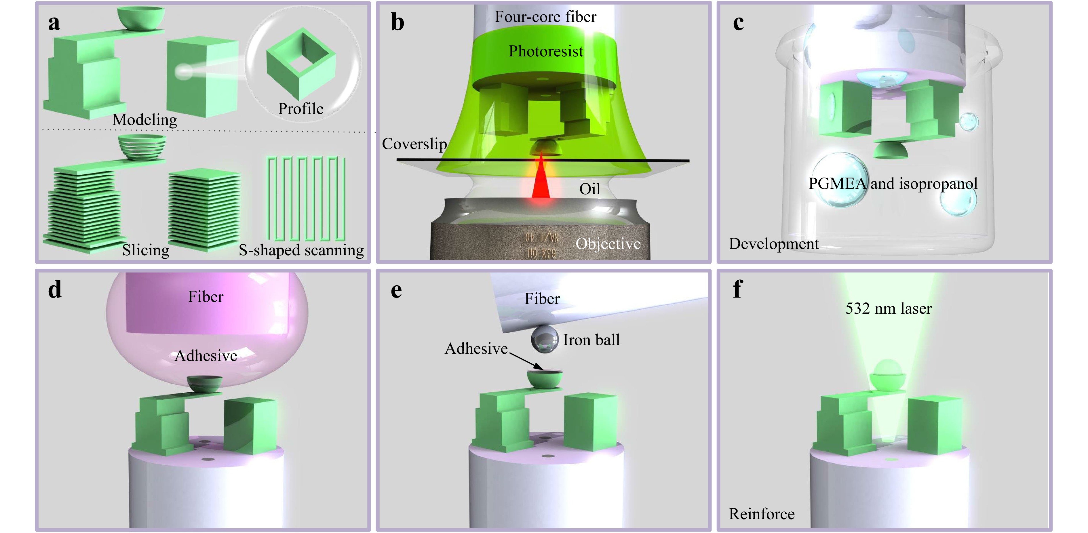
Fig. 3 Flowchart illustrating device fabrication. a Modeling and scanning path design. b Polymerization of the micro/nanostructures on the MCF end facet. c Sample development (removal of unpolymerized photoresist. d Coating of the adhesive. e Microcantilever is incorporated with an iron ball. f Photoresist is solidified by the light emitted from the fiber core to reinforce the sample.
The geometric arrangement of fiber tip (four-core MCF), photoresist (IP-L), coverslip (170 mm thickness), matching oil (RI=1.518), and an objective lens (63×, NA=1.4) are shown in Fig. 3b. The laser power (5 mW) and scanning speed (50 mm/s) were optimized according to the planned scanning path during TPP. Scanning of the laser exposure point was implemented by moving the piezoelectric stage, which has the advantages of high precision and repeatability. After polymerization, the sample was developed using Propylene Glycol Methyl Ether Acetate (PGMEA) and isopropyl alcohol solutions successively to remove the unexposed photoresist, as shown in Fig. 3c, which retains the cured microcantilever and liquid polymer encapsulated inside the microcavity. To ensure that the bowl-shaped structure adhered to the iron ball, an adhesive was applied to the hollow bowl, as shown in Fig. 3d. A small amount of green light-cured adhesive collected by a fiber tip was placed into the hollow bowl by slowly moving the displacement stage. Fig. 3e shows the process of assembling the iron ball into the hollow bowl. Under the action of van der Waals forces29, the iron ball is captured by the fiber and assembled using the slowly moving displacement stage. Finally, the adhesive inside the hollow bowl was solidified to reinforce the sample by irradiating it with a 532 nm laser from the fiber core (Fig. 3f).
The four-core MCF and printed micro/nanostructures were characterized using scanning electron microscopy (SEM), as shown in Fig. 4. The multicore fiber (SM-4C1500) from Fibercore Ltd. had four cores arranged in a square pattern, with diameters for cladding, core, and mode field of 125 µm, 8 µm, and 8.4 µm, respectively, and core-to-core spacing of 50 µm. The large core spacing provides space for the fabrication of long microcantilever with high sensitivity and ensures the independence of the two FPIs. Fig. 4b–d show the printed micro/nanostructures obtained from different angles. Both the microcantilever and microcavity can be clearly distinguished. The microcantilever with a length of 40 μm, a width of 20 μm and a thickness of 2 μm and the hollow bowl with a diameter of 30 μm were completely printed onto the fiber end facet. Moreover, the smooth surface of the microcantilever and the good parallelism between the microcantilever and the fiber end facet contributed to the efficient excitation of the interference spectrum. It is worth noting that there is a 10 × 10 μm hollow region fabricated in the middle of the microcantilever to improve mechanical deformation sensitivity16. Another FPI is a microfluid-infiltrated microcavity, which has a bottom area of 30 × 30 μm, a side-wall thickness of 5 μm, and a top wall thickness of 2 μm. The box-shaped microcavity was completely printed and tightly enclosed on all sides, successfully enclosing the microfluidic polymer. Both micro/nanostructures were printed on different fiber core end facets at designed positions, reflecting the light from different fiber cores, thus forming the FPIs of air and liquid polymer mediums, respectively.
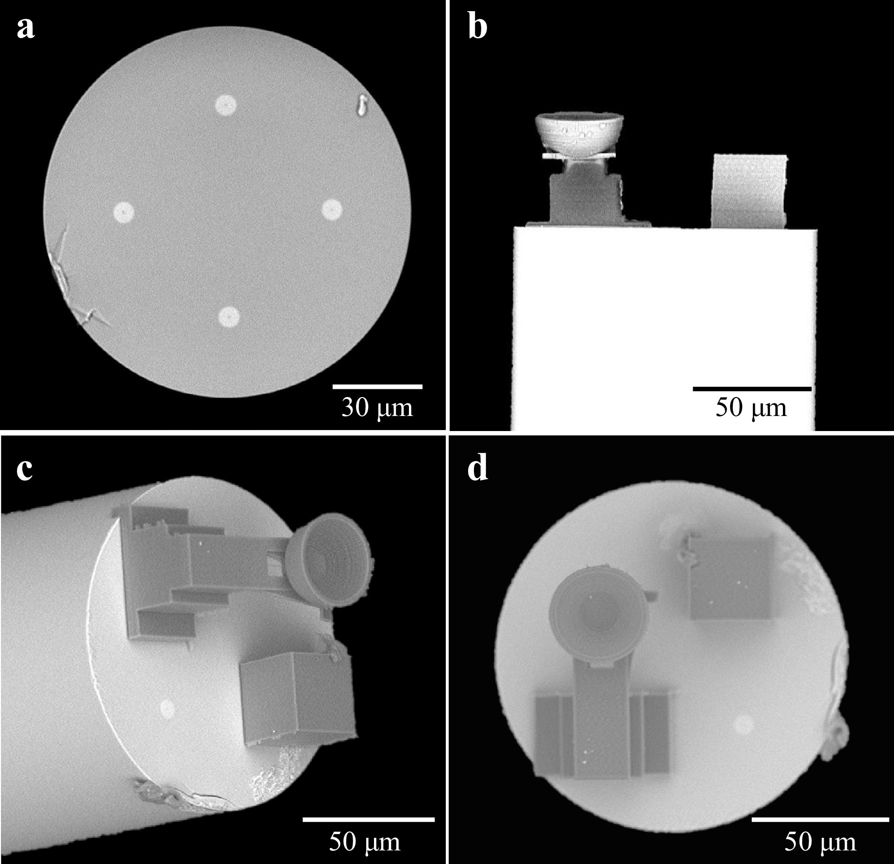
Fig. 4 Scanning electron micrographs. a Four-core MCF. b-d Microcantilever and microfluid-infiltrated microcavity.
The reflection spectra of the sensor were investigated by connecting a broadband source (BBS), optical spectrum analyzer (OSA), 3 dB coupler, optical switch, and a sample with an MCF fan-in/out device30, as shown in Fig. 5a. The reflection spectrum of microcantilever illustrates a dip wavelength with a fringe visibility of 4.27 dB and a free spectrum range (FSR) of 31.30 nm at 1550.8 nm, whereas the reflection spectrum of microfluid-infiltrated microcavity shows a dip wavelength with a fringe visibility of 6.28 dB and an FSR of 23.65 nm at 1531.3 nm (Fig. 5b). The reflection spectra of the dual FPIs had a large FSR, which is conducive to a wide range of measurements.
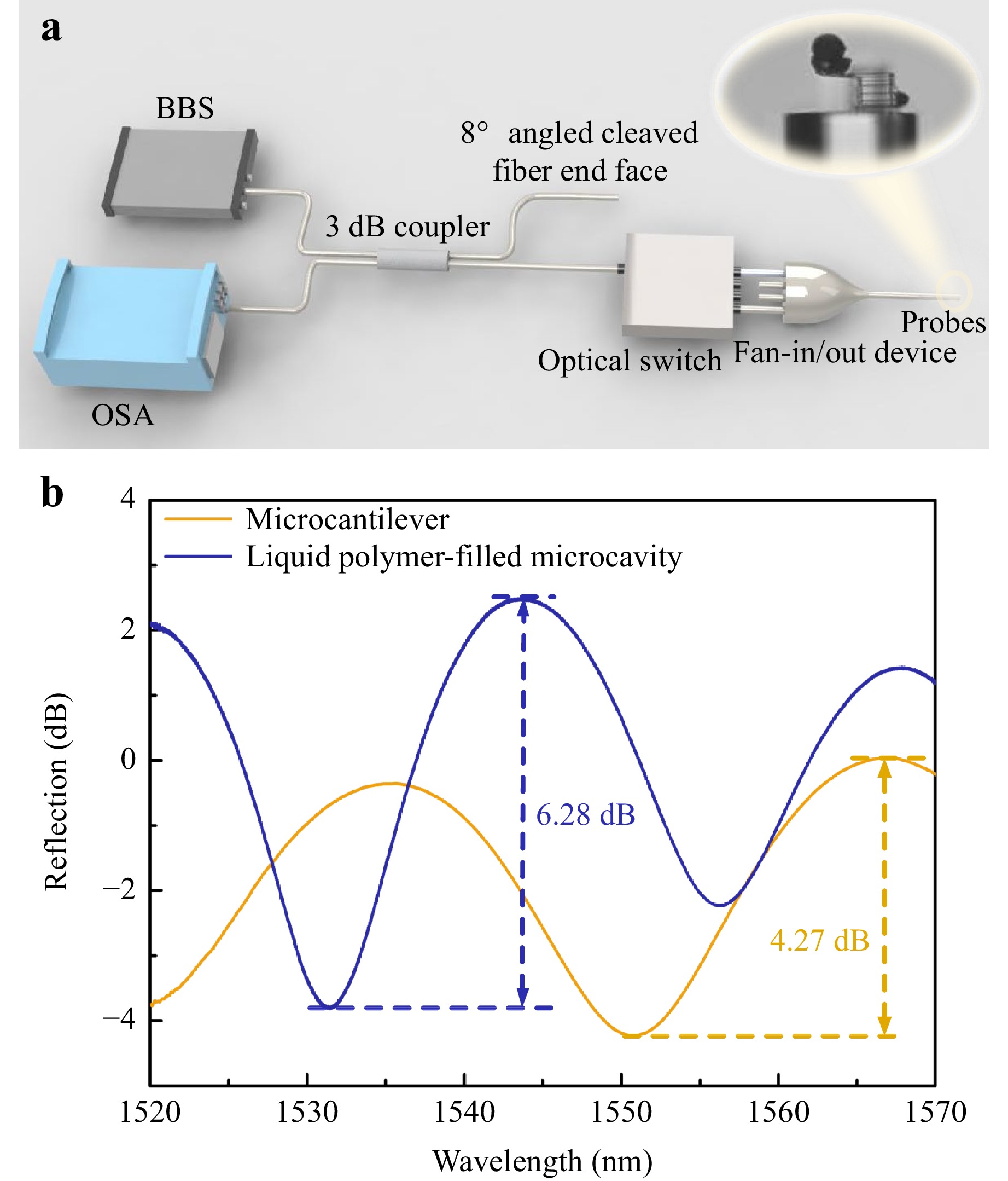
Fig. 5 a Scheme of spectral measurement. b Reflection spectra of the dual FPIs.
-
The magnetic-field intensity of the sensor was measured in a magnetic-field environment generated by a magnet and calibrated using a Gaussian meter. Fig. 6 shows the response of the microcantilever incorporated with a ~30 μm diameter iron ball to various magnetic field intensities. As shown in Fig. 6a, as the magnetic field intensity increases from 30 to 90 mT, the red shift in the reflection spectrum is 7.6 nm, indicating that the cavity length of FPI-1 increases. This can be attributed to the increase in the magnetic force acting on the iron ball when the magnetic field intensity increases, resulting in a larger upward deformation of the microcantilever. In Fig. 6b, the variation in the traced dip wavelength is plotted as a function of magnetic field intensity, showing low- and high-sensitivity areas. The performance of the sensor was relatively stable, and the error bar of each measurement point was calculated through two testing cycles, all less than 0.25 nm. Notably, the slope of the dip wavelength shift is not a linear function of the magnetic field intensity over the entire measurement range; however, this sample can be fitted with a slope of 154.5 pm/mT with good linearity (R2 = 0.97) in the range of 50–90 mT (Inset of Fig. 6b).
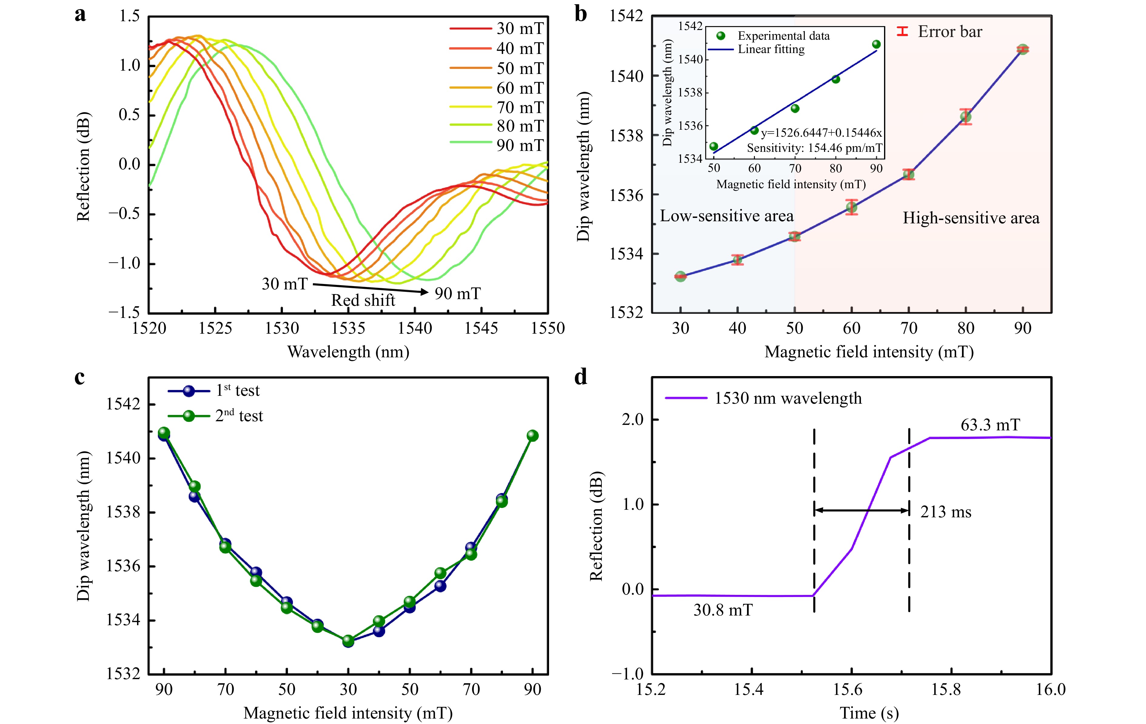
Fig. 6 Magnetic field response of microcantilever incorporated with a ~30 μm diameter iron ball. a Reflection spectra vs. magnetic field intensity. b Variation of dip wavelength with magnetic field intensity. c Repeatability test in two cycles of magnetic field intensity measurement. d Response time measurement.
The repeatability of the sensor was investigated using two cycles of magnetic-field intensity measurements. Fig. 6c shows the variation in the dip wavelength with magnetic field intensity during cycling. The dip wavelength at different magnetic field intensities is relatively stable regardless of whether the magnetic field intensity increases or decreases. The results indicate that the magnetic field sensor has good repeatability, attributed to the excellent recovery of the polymer microcantilever.
The response time of the sensor was investigated by recording the light intensity variation in the reflection spectrum at 1530 nm at varying magnetic field intensities. Fig. 6d illustrates the light intensity variation of the scanning wavelength when the magnetic field intensity increases from 30.8 to 63.3 mT. The response time is defined as the time interval for the sensor to reach 90% of the steady-state response31. The response time of the sensor was estimated to be 213 ms, which indicates that the sensor can respond quickly to changes in magnetic field intensity.
To further verify the repeatability and stability of the sensor, a microcantilever incorporated with a ~43 μm diameter iron ball was implemented to test five cycles of magnetic field measurements. The variation in the dip wavelength with magnetic field intensity during the five testing cycles is shown in Fig. 7a. The dip wavelength is stable during each measurement, and the wavelength dip points in the five cycles are almost coincident, indicating that the sensor has good repeatability in the magnetic field range of 30-60 mT. Fig. 7b illustrates the low- and high-sensitivity areas of the sample. The error bars of the dip wavelengths at different magnetic field intensities in the five testing cycles were calculated to be less than 0.28 nm. The inset of Fig. 7b shows the dip wavelength as a linear function of the magnetic field intensity over 30–50 mT, exhibiting a sensitivity of 322.3 pm/mT.
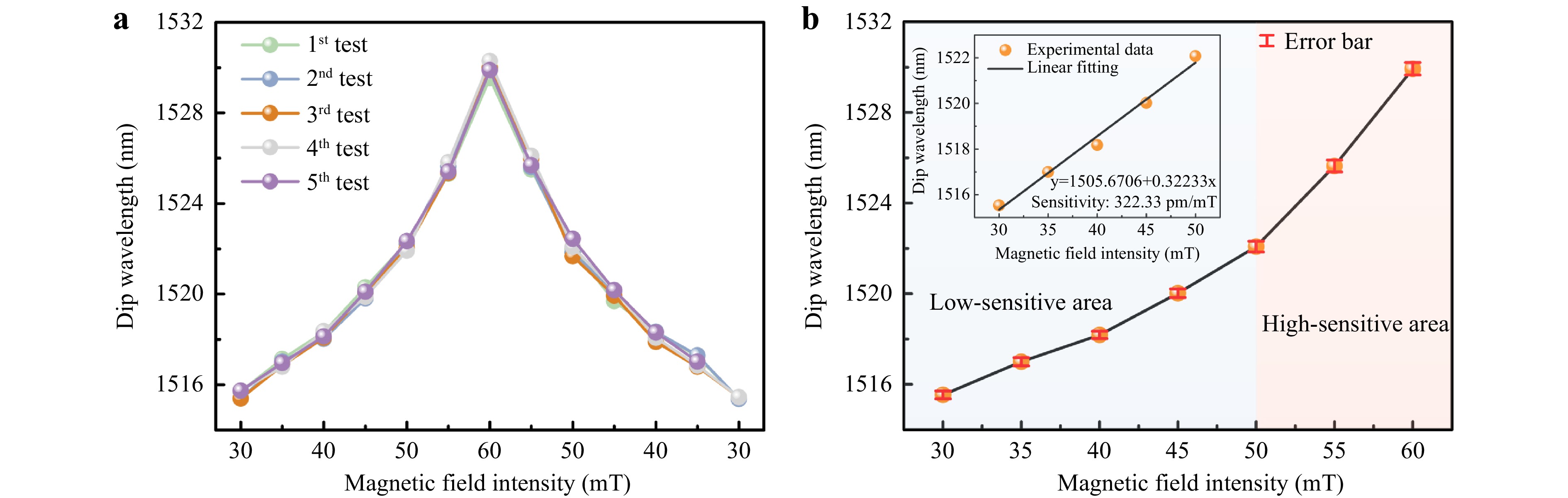
Fig. 7 Magnetic field response of microcantilever incorporated with a ~43 μm diameter iron ball. a Five cycle repeatability test of magnetic field intensity measurements. b Variation of dip wavelength with magnetic field intensity.
To investigate the influence of iron ball size on the sensitivity of the sensor, a microcantilever incorporated with a ~61 μm diameter iron ball was implemented to measure the magnetic field intensity. As shown in Fig. 8a, the reflection spectrum redshift value of the sample is 17.81 nm when the magnetic field intensity increases from 30 to 40 mT. In Fig. 8b, the shift of the traced dip wavelength is plotted as the magnetic field increases from 30 to 48 mT. The trend of magnetic field sensitivity variation is consistent with that of the sample incorporated with 30 μm diameter iron ball, that is, the sensitivity increases with an increase in magnetic field intensity. In the inset of Fig. 8b, the traced dip wavelength is a linear function of the magnetic field intensity in the range of 30–40 mT, and the sensitivity reaches 1805.6 pm/mT. Therefore, the magnetic field intensity sensitivity of the sensor can be improved by incorporating a larger iron ball, which causes the microcantilever to be subjected to a stronger magnetic force in the same magnetic field.
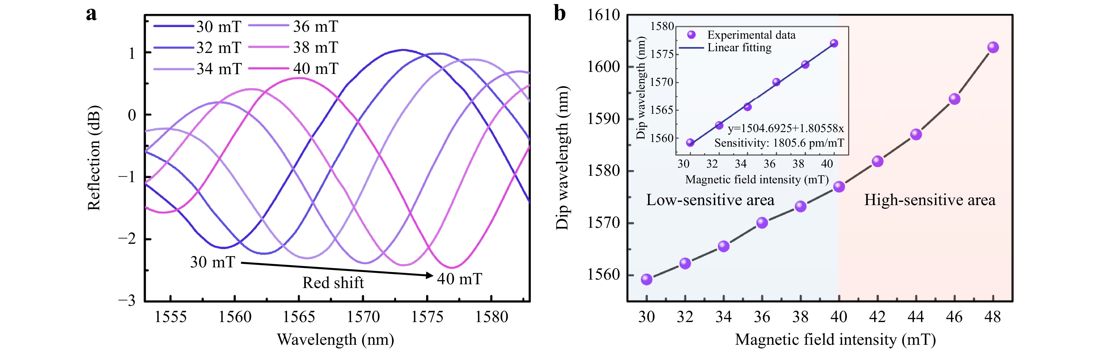
Fig. 8 Magnetic field response of microcantilever incorporated with a ~61 μm diameter iron ball. a Reflection spectra vs. magnetic field intensity. b Variation of dip wavelength with magnetic field intensity.
Temperature is an important physical parameter affecting the measurement accuracy of sensors. To investigate the temperature characteristics of the sensor, the temperature was measured in the range of 25–55℃ in increments of 5℃ steps by placing the sensor in an electric oven. Each measurement point was maintained for 10 min to ensure an adequate response. Fig. 9a shows the reflection spectra of the microcantilever at various temperatures; a redshift in the reflection spectrum is observed as the temperature increases. The dip wavelength at each measuring point was linearly fitted, obtaining a sensitivity of 77.4 pm with a standard error of 3.2 pm (Fig. 9b). Similarly, a red shift in the reflection spectrum of the microfluid-infiltrated microcavity is observed as temperature increases, as shown in Fig. 9c. The linear fit in Fig. 9d of the experimental data at each temperature shows a high sensitivity of 160.3 pm/℃, with a standard error of 3.8 pm. The spectral redshift of the FPI as a function of temperature can be expressed as15,
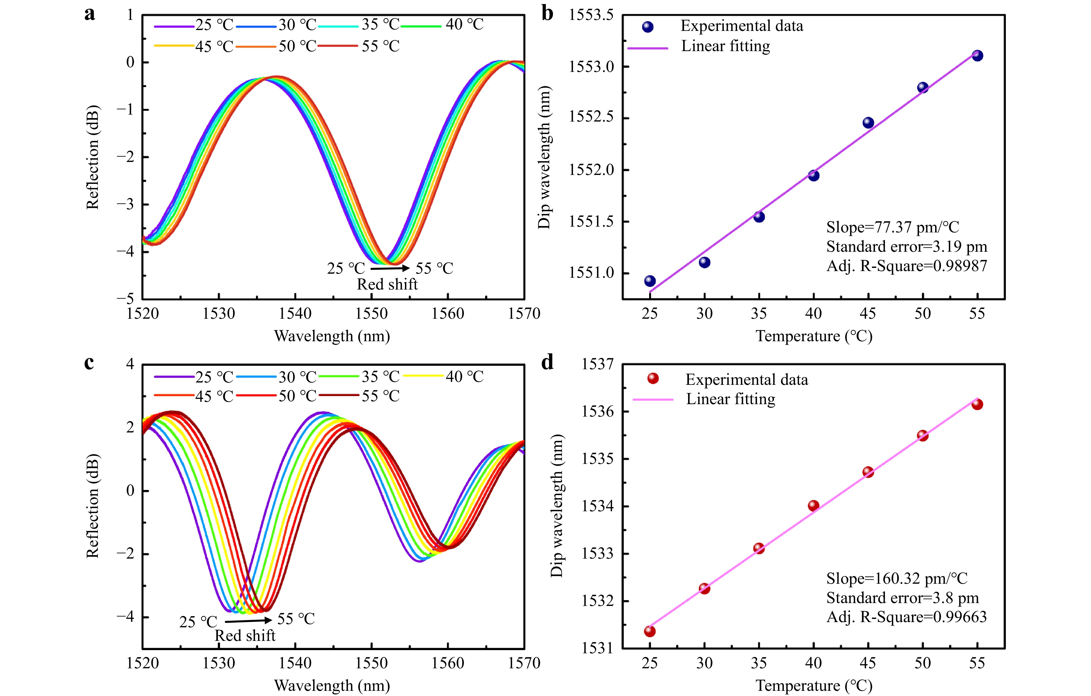
Fig. 9 Temperature response of the microcantilever and the microfluid-infiltrated microcavity. a Reflection spectra of microcantilever vs. temperature. b Linear fitting of the dip wavelength of microcantilever as a function of temperature. c Reflection spectra of microfluid-infiltrated microcavity vs. temperature. d the linear fitting of the dip wavelength of microfluid-infiltrated microcavity as a function of temperature.
$$ \frac{{{\text{d}}\lambda }}{{dT}} = \frac{2}{k}\left(\frac{{dn}}{{dT}}L + \frac{{dL}}{{dT}}n\right) $$ (9) where $ ({{d\lambda }})/({{dT}}) $ is the shift in dip wavelength with a variation in temperature; $ k $ is the interference order number; $ ({{dn}})/({{dT}}) $ is the thermo-optic coefficient of the medium in the FP cavity; and $ ({{dL}})/({{dT}}) $ is the thermo-expansion coefficient of the FP cavity.
In FPI-1, because the RI of air changes with temperature are indistinguishable, the redshift of the spectrum is attributed primarily to the increased cavity length from the thermal expansion of the polymer base of the microcantilever. In FPI-2, the redshift of the spectrum is caused by a combination of the thermo-optic and thermo-expansion effects of the liquid polymer in the microcavity. As temperature increases, the RI of the liquid decreases32, which leads to the blue shift in the spectrum. However, this blueshift is weak compared to the redshift caused by the thermal expansion of the liquid; thus, the spectrum eventually appears as a spectral redshift. Compared with FPI-1, the increased temperature sensitivity of FPI-2 is due to the fact that the liquid polymer has a higher thermal expansion coefficient than the cured polymer microcantilever base of FPI-126. Because the photoresist-infiltrated microcavity may solidify over long-term light exposure, the temperature-sensing element should be further packaged light-free, or another stable microfluid can be embedded inside the hybrid microfluidic cavity.
As the microfluid-infiltrated microcavity was not incorporated into the iron ball, it was not sensitive to the magnetic field, and the magnetic field intensity sensitivity was 0 pm/mT. Therefore, for the microcantilever sample incorporated with a ~61 μm diameter iron ball, Eq. 8 can be expressed as
$$ \left[ \begin{gathered} _{}^{}\Delta {\lambda _1}_{}^{} \\ _{}^{}\Delta {\lambda _2}_{}^{} \\ \end{gathered} \right] = {\left[ \begin{gathered} {}_{}1805.6 \\ _{}{}_{}0 \\ \end{gathered} \right._{}}_{}\left. \begin{gathered} {}_{}{77.4^{}} \\ {160.3^{}} \\ \end{gathered} \right]_{}^{}\left[ \begin{gathered} _{}^{}\Delta H_{}^{} \\ _{}^{}\Delta T_{}^{} \\ \end{gathered} \right] $$ (10) The magnetic field intensity and temperature can be measured simultaneously by monitoring the spectra of the dual FPIs based on Eq. 10. The condition number of the two-parameter sensor21 based on the calculated measured sensitivity was 11.28, which indicates that the MCF-tip multi-parameter sensor has reliable stability and high tolerance to the measurement error of the dip wavelength shift. Various previous typical fiber-based magnetic field and temperature-discriminative sensors are summarized for comparison in Table 1. The proposed MCF-tip dual FPIs sensor is smaller and has a lower condition number, making it superior to most similar sensors.
Sensor type Structure size
(mm)Magnetic field
sensitivity (pm/mT)Temperature sensitivity
(pm/℃)Condition number Ref. PCF-FBG >10 924.6 123.1 94.38 12 FPI-FBG >1 340 −92 28.07 33 PCF-FPI >1 330 −236 1.62 34 MZI-FBG >15 407.8 −362.6 61.73 35 Microfiber-MZI >0.263 −11930 1950 35.55 36 PCF multimodal interferometer >1 720 −80 20.79 37 MCF-tip dual FPIs 0.125 1805.6 160.3 11.28 Our work PCF: Photonic crystal fiber; FBG: Fiber Bragg grating; FPI: Fabry-Perot interferometer; MZI: Mach-Zender interferometer Table 1. Performance comparison of fiber-based magnetic field and temperature discriminative sensors.
To verify the reliability of the dual-parameter discriminative sensor, its performance was tested under different environments for random magnetic field intensities and temperature settings. For the magnetic field intensity and temperature measurements, our fiber tip probe and a commercial electric probe were placed in a temperature oven with a magnetic field to create a two-parameter measurement environment with an adjustable magnetic field and temperature. The magnetic field intensity and temperature in the initial environment were 30 mT and 25℃, respectively. The spectra of the dual probes in the initial environment were used as reference to calculate the variation in the spectra resulting from environmental changes. Based on Eq. 10, the measured two-parameter variation was calculated according to the measured wavelength shift of the dual FPIs, as shown in Table 2. The results of five random measurement points demonstrated that the relative measurement errors of the magnetic field intensity and temperature were less than 0.71% and 5.06%, respectively, confirming that the proposed MCF-tip dual-probe sensor with low condition number is reliable. More importantly, without temperature discriminative measurements, the magnetic field measurement error goes up to 53% (measurement of magnetic field variations over actual magnetic field variations) as the actual magnetic field changes from 30 to 32 mT with the temperature changing from 25–50 ℃ and increases by only 5% in the case of discriminative measurement.
Random magnetic field
and temperature settingWavelength
shift of FPI-1Wavelength
shift of FPI-2Measured parameters variation Measured magnetic
field and temperatureRelative measurement errora H = 32 mT
T = 40℃4.83 nm 2.26 nm ΔH = 2.07 mT
ΔT = 14.10℃H′ = 32.07 mT
T′ = 39.10℃0.22%
2.25%H = 34 mT
T = 55℃8.94 nm 4.45 nm ΔH = 3.76 mT
ΔT = 27.76℃H′ = 33.76 mT
T′ = 52.76℃0.71%
4.07%H = 38 mT
T = 35℃14.61 nm 1.32 nm ΔH = 7.74 mT
ΔT = 8.23℃H′ = 37.74 mT
T′ = 33.23℃0.68%
5.06%H = 32 mT
T = 50℃5.52 nm 3.61 nm ΔH = 2.09 mT
ΔT = 22.52℃H′ = 32.09 mT
T′ = 47.52℃0.28%
4.96%H = 40 mT
T = 25℃18.50 nm 0.09 nm ΔH = 10.22 mT
ΔT = 0.56℃H′ = 40.22 mT
T′ = 25.56℃0.55%
2.24%a Relative measurement error = (|H' − H|/H) × 100% or (|T' − T|/T) × 100% Table 2. Performance of MCF-tip dual-probes in different environments with random magnetic field intensity and temperature settings.
-
In summary, we demonstrated an ultracompact MCF-tip probe for the discriminative measurement of magnetic field and temperature. The microcantilever and microfluid-infiltrated microcavity integrated on the MCF end facet were 3D-printed by femtosecond laser-induced TPP. The microcantilever incorporated with iron ball demonstrated a magnetic field intensity sensitivity of 1805.6 pm/mT and a temperature sensitivity of 77.4 pm/℃. The microfluid-infiltrated microcavity exhibited a temperature sensitivity of 160.3 pm/℃. The two functional probes exhibited different sensitivities to the magnetic field and temperature; thus, the two parameters can be discriminatively measured by calculating the multi-parameter sensitivity coefficient matrix. The MCF-tip dual-FPIs had the smallest size and exhibited a low condition number of 11.28, which is superior to that of most similar sensors, demonstrating the importance of discriminative measurements during external temperature changes. The finesse of the microcantilever can be improved by depositing high-reflectivity coatings onto the fiber end facet and polymer microcantilever surface, which further enhances the performance of the discriminative sensor. Therefore, the bowl-shaped microcantilever can provide a useful hybrid platform for incorporating 3D printed microstructures with functional materials, thereby breaking the restrictions on the range of detectable parameters. MCF-based fiber-tip probes can also be powerful tools for multi-parameter sensing in extremely limited sensing spaces.
-
This work was supported by the National Natural Science Foundation of China (No. 62275052, No.62275148), Shanghai 2021 Science and Technology International Cooperation Project “Program of Action for Science and Technology Innovation” (21530710400), the Jiangsu Province's Industry Outlook and Key Core Technologies-Key Projects (BE2022055-4), the Open Fund of Laboratory of Science and Technology on Marine Navigation and Control, China State Shipbuilding Corporation (2023010102).
3D printed multicore fiber-tip discriminative sensor for magnetic field and temperature measurements
- Light: Advanced Manufacturing , Article number: (2024)
- Received: 05 December 2023
- Revised: 14 March 2024
- Accepted: 18 March 2024 Published online: 27 March 2024
doi: https://doi.org/10.37188/lam.2024.018
Abstract: Miniaturized fiber-optic magnetic field sensors have attracted considerable interest owing to their superiorities in anti-electromagnetic interference and compactness. However, the intrinsic thermodynamic properties of the material make temperature cross-sensitivity a challenging problem in terms of sensing accuracy and reliability. In this study, an ultracompact multicore fiber (MCF) tip sensor was designed to discriminatively measure the magnetic field and temperature, which was subsequently evaluated experimentally. The novel 3D printed sensing component consists of a bowl-shaped microcantilever and a polymer microfluid-infiltrated microcavity on the end-facet of an MCF, acting as two miniaturized Fabry-Perot interferometers. The magnetic sensitivity of the microcantilever was implemented by incorporating an iron micro ball into the microcantilever, and the microfluid-infiltrated microcavity enhanced the capability of highly sensitive temperature sensing. Using this tiny fiber-facet device in the two channels of an MCF allows discriminative measurements of the magnetic field and temperature by determining the sensitivity coefficient matrix of two parameters. The device exhibited a high magnetic field intensity sensitivity, approximately 1805.6 pm/mT with a fast response time of ~ 213 ms and a high temperature sensitivity of 160.3 pm/℃. Moreover, the sensor had a low condition number of 11.28, indicating high reliability in two-parameter measurements. The proposed 3D printed MCF-tip probes, which detect multiple signals through multiple channels within a single fiber, can provide an ultracompact, sensitive, and reliable scheme for discriminative measurements. The bowl-shaped microcantilever also provides a useful platform for incorporating microstructures with functional materials, extending multi-parameter sensing scenarios and promoting the application of MCFs.
Research Summary
Miniaturized discriminative sensing: 3D printed multicore fiber-tip probes
Multicore fiber contains multiple optical transmission channels in a single fiber, providing the advantages of high integration and space division multiplexing. The 3D printing technique can efficiently fabricate multiple customized sensing elements on the end facet of multicore fiber, making it widely utilizable in ultracompact fiber-tip devices with an exquisite structure incorporating functional materials. Li-Min Xiao from China’s Fudan University and colleagues now report a 3D printed multicore fiber-tip composite probes for magnetic field and temperature discriminative sensing. The multi-probes can provide an ultracompact, sensitive, fast, and reliable scheme for discriminative measurement, especially the size of sensing space is extremely limited. The bowl-shaped microcantilever can provide a useful hybrid platform for incorporating 3D printed microstructures with fruitful functional materials.
Rights and permissions
Open Access This article is licensed under a Creative Commons Attribution 4.0 International License, which permits use, sharing, adaptation, distribution and reproduction in any medium or format, as long as you give appropriate credit to the original author(s) and the source, provide a link to the Creative Commons license, and indicate if changes were made. The images or other third party material in this article are included in the article′s Creative Commons license, unless indicated otherwise in a credit line to the material. If material is not included in the article′s Creative Commons license and your intended use is not permitted by statutory regulation or exceeds the permitted use, you will need to obtain permission directly from the copyright holder. To view a copy of this license, visit http://creativecommons.org/licenses/by/4.0/.

 DownLoad: