-
In the past few decades, increased communication traffic has significantly increased the capacity of optical communication systems, thereby causing the rapid development of modern communication technology1. The demand for a higher communication capacity is unstoppable; however, the data capacity of single-mode fibres is limited by the Shannon limit caused by optical nonlinearities2. To overcome this limit, space-division multiplexing (SDM) technology has been proposed as a promising alternative3. SDM technology includes multi-core division multiplexing, in which multiple single-mode cores are placed into a common cladding, and mode division multiplexing (MDM), in which different orthogonal modes transmitted in one few-mode fibre (FMF) are used as individual data channels4–6. Furthermore, SDM significantly improves the spectral and energy efficiency, reducing the cost per transmitted bit compared with individual single-mode fibres. Spatial multiplexers, including mode (de)multiplexers and multi-core fan-in/fan-out (FIFO) devices, are the most crucial configurations in SDM technology7–9. Recently, MDM (de)multiplexers have rapidly developed as on-chip MDM systems, and have received increased attention. Commonly used free-space mode multiplexers such as phase plates10 and liquid-crystal spatial light modulators (SLMs)11 are elaborate and typically lossy. Compared with a large free-space optical system, integrated optics realise more efficient, faster, and higher-dimensional multi-functional information processing with the advantages of small size, low loss, high integration, and high scalability12.
Traditional optical waveguide fabrication techniques such as ion implantation13, proton exchange14, thin-film deposition, and metal ion diffusion15 limit optical waveguides to one-dimensional (1D) planar structures. Although two-dimensional (2D) optical waveguides can also be fabricated using lithography technology, they do not meet the needs of modern integrated optics development. Fortunately, with the continuous development of high-performance ultrafast laser technology, femtosecond laser fabrication technology has rapidly developed since the 1990s16. Femtosecond laser fabrication technology is widely used in basic and applied research in many fields, particularly for providing a flexible and efficient true three-dimensional (3D) fabrication method for monolithic components in integrated optics17,18. Femtosecond laser fabrication technology has the unique advantages of 3D fabrication, arbitrary structural design, high fabrication resolution, and a wide range of applicable materials, making it ideal for photonic-lantern mode (de)multiplexer fabrication19–23. Ideally, a mode (de)multiplexer based on femtosecond laser fabrication technology should be compact, entirely passive, and compatible with few-mode fibres.
Currently, there are many on-going studies on photonic-lantern mode division multiplexed transmission through ultrafast laser-inscribed mode multiplexers. Under no special design, simply using consistent waveguides to form photon-lantern structures will result in the inability to achieve selective mode excitation22. To achieve selective mode excitation, Guan et al.23 used dissimilar waveguides along symmetry trajectories in the coupling region to form a three-channel mode-group-selective photonic lantern via ultrafast laser inscription with a 4-dB loss. Gross et al.24 reported ultrafast laser-inscribed mode-group-selective six-mode photonic lanterns using a similar design with a 4.7-dB insertion loss. Although these designs follow the fibre-type photonic-lantern mode (de)multiplexer principles, problems such as inconsistent waveguide transmission losses, inconsistent coupled losses, and inefficient selective mode excitation still exist. Furthermore, the insertion losses and mode quality of these devices are relatively poor, making them unsuitable for practical applications.
In this study, we demonstrated superior ultrafast laser inscribed photonic-lantern mode (de)multiplexers using trajectory asymmetry with uniform waveguides. Nonuniform waveguides of different sizes can lead to inconsistent waveguide transmission and coupling losses. The uniform optical waveguides with ultra-low transmission and coupling losses of 0.1 dB/cm and 0.2 dB/facet, respectively, are obtained. With the trajectory-asymmetric structure, the femtosecond laser inscribed photonic-lantern mode (de)multiplexer can efficiently and selectively excite three modes (LPa11, LPb11, and LP01) with high purity. The intensity profiles of the transmitted beams were captured and the insertion losses were measured. These devices were found to be polarisation insensitive. Furthermore, we demonstrate six-channel (LPa11x, LPa11y, LPb11x, LPb11y, LP01x, and LP01y) mode- and polarisation-division multiplexing and demultiplexing systems. Subsequently, the crosstalk in the system was measured. Finally, we demonstrate a high-speed communication experiment with 42 Gaud/s QPSK signals based on six-channel mode- and polarisation-division multiplexing and demultiplexing systems. The bit error rate (BER) of the systems was also measured.
-
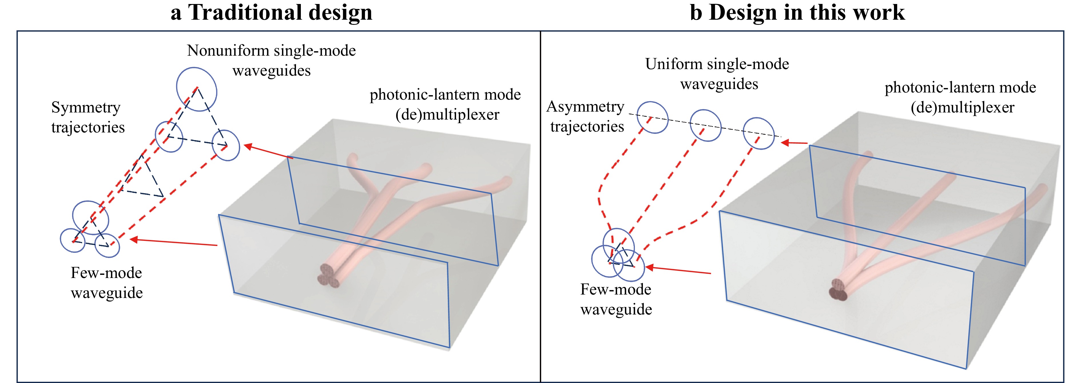
Photonic lanterns are 3D waveguide devices that convert N single-mode waveguides into few-mode waveguides that support N modes. Mode-selective excitation is the key principle of photonic-lantern mode (de)multiplexers, which allows the selective excitation and multiplexing of diverse LP modes. Fabricating a mode multiplexer that excites each mode of a few-mode fibre without loss is challenging because the spatial modes of the fibre are spatially overlapping and cannot be simply separated. Mode selectivity in a mode multiplexer is useful for equalising mode-dependencies such as mode-dependent losses. By breaking the symmetry between the modes and avoiding mode coupling, mode selectivity can be introduced into the photonic-lantern mode multiplexer. Photonic lanterns were originally fabricated using a fibre-tapering technique that tapered multiple single-mode fibres along symmetrical trajectories. Using dissimilar single-mode fibres, asymmetry was introduced to achieve mode selectivity. A traditional photonic lantern design using femtosecond laser fabrication technology follows a fibre-type design, as shown in Fig. 1a. The nonuniform single-mode waveguides were placed in symmetric positions across the vertical symmetry axis of the arrangement and along the vertical axis of the preform. Nonuniform waveguides were fabricated using different laser powers. Finally, the few-mode waveguide was composed of strongly coupled single-mode waveguides.

Fig. 1 Schematic of photonic lantern mode (de)multiplexers. a Traditional design using trajectory-symmetry with nonuniform single-mode waveguides. b Proposed design using trajectory-asymmetry with uniform single-mode waveguides.
By contrast, the proposed design uses uniform single-mode waveguides along asymmetric trajectories to form a few-mode waveguide, as shown in Fig. 1b. All single-mode waveguides were fabricated using the same fabrication parameters and properties. The middle waveguide was a straight waveguide, whereas the two sides were bent waveguides, forming an asymmetric trajectory. This design can yield different coupling conditions among all waveguides along the coupled region, ensuring different propagation constants for each supported mode in the final few-mode waveguide. Thus, mode selectivity was achieved using an asymmetric trajectory. Femtosecond-laser fabrication technology can achieve an overlap between waveguides, which can better adjust the size of few-mode waveguides.
Next, details regarding the femtosecond laser fabrication are discussed. As shown in Fig. 2a, a femtosecond laser fabrication system with a high-repetition-rate ytterbium-based laser (double frequency 515 nm wavelength, 100 kHz repetition rate, and 234 fs pulse duration) was used in this study. An ultraviolet optical quartz glass (JGS2) sample was placed on a high-precision XYZ air-bearing stage. The linear polarisation femtosecond laser is vertically focused ~70 μm below the top surface of the glass sample through a 50X0.42 objective (M Plan Apo NIR, Mitutoyo). Using a light-emitting diode (LED) lighting system, the femtosecond laser direct writing process was monitored in real time using a charge-coupled device (CCD). A 300-nm linear slit was used to modify the laser beam profile, as shown in Fig. 2b. The laser beam diameter before the slit was approximately 1.5 mm. The pulse energy was measured as 9 μJ/0.75 μJ before or after the slit. In general, the cross section of a femtosecond laser-inscribed waveguide in glass appears as an elongated ellipse along the femtosecond laser propagation direction with a large aspect ratio owing to conventional spherical focusing optics25. Strong core asymmetry, which corresponds to a complicated refractive-index distribution, can cause significant path loss. By inserting a slit before the focusing lens with the slit oriented parallel to the laser scanning direction, the aspect ratio in the waveguide cross-section can be significantly reduced, producing low-loss circular waveguides in glass26–28. Additionally, circular waveguides exhibit better mode-field matching with fibres. A femtosecond laser inscribed photonic-lantern mode (de)multiplexer in a glass chip is shown in Fig. 2c. An image of the output-side cross-section of the mode multiplexer is shown in Fig. 2d. An enlarged image of the three mode multiplexer input ports is shown in Fig. 2e.
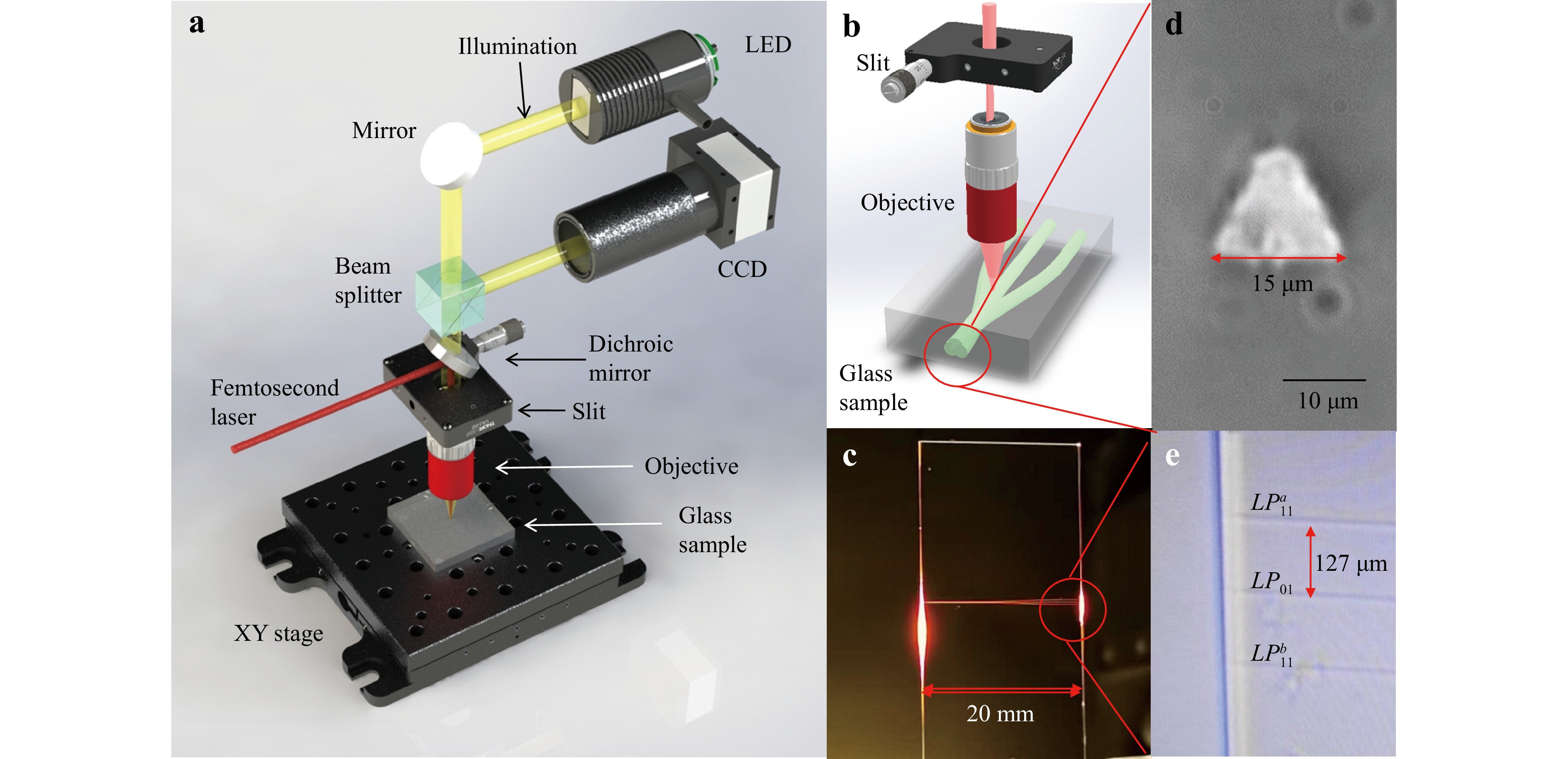
Fig. 2 Femtosecond laser 3D fabrication system and fabricated devices. a Femtosecond laser 3D fabrication system. b Femtosecond laser direct writing the structure of the three-port photonic-lantern mode (de)multiplexer. c Photo of the three-port photonic-lantern mode (de)multiplexer in a glass chip. d Output-side cross-sectional image of the mode multiplexer. e Enlarged image of the three mode multiplexer input ports.
The properties of optical waveguides fabricated using femtosecond lasers are affected by various fabrication parameters. In traditional designs, the optical waveguide size is controlled by changing the femtosecond laser power or by changing the number of scans, which essentially influence the energy magnitude deposited in the material to modify the range and degree of material modification. Variations in the optical waveguide properties also affect the transmission loss of optical waveguides and the coupling loss with optical fibres. To study the optimal waveguide fabrication parameters, a series of optical waveguides were inscribed using a femtosecond laser in 2-cm-long quartz glass by changing the femtosecond laser power from 54 to 87 mW. Both ends of the waveguides were pigtailed by commercial single-mode fibres (waveguide diameter: 9 μm). One side of the fibre was connected to a 1550-nm laser, while the other side was connected to an optical power meter. The transmission losses of the 2-cm waveguides were measured, as shown by the black line in Fig. 3. The coupling losses on one side were measured using the truncation method, as indicated by the red line in Fig. 3. The transmission losses of the waveguides were also calculated, as indicated by the blue line in Fig. 3. The waveguide cross-sections at 54, 75, and 87 mW are marked in Fig. 3, with waveguide sizes of 6.3, 9.0, and 10.5 μm, respectively. The higher the laser power, the larger the waveguide size. For a laser power of 75 mW, the minimum insertion loss is 0.63 dB, with coupling and waveguide transmission losses of 0.21 dB/facet and 0.1 dB/cm, respectively. When the laser power is low, the refractive index difference is also low, which prevents the waveguides from effectively constrain the beams, causing greater waveguide transmission losses. As the laser power increases, defects are introduced into the waveguide during fabrication, causing a decrease in the waveguide smoothness and resulting in higher transmission losses. Meanwhile, the size of a single-mode fibre is between 9 and 10 microns. Therefore, the size of the single-mode waveguides must match that of the corresponding optical fibres to achieve the lowest coupling loss possible. The mismatch between the waveguide and fibre sizes can also increase the coupling losses. Therefore, nonuniform waveguides can lead to inconsistent waveguide transmission and coupled losses. By using uniform single-mode waveguides, ultra-low waveguide transmission and coupled losses of 0.1 dB/cm and 0.2 dB/cm, respectively, at 1550 nm are obtained. As can be seen in Fig. 3, when the laser power is between 69 and 81 mW, the waveguide insertion loss can be maintained below 1 dB, and the corresponding mode multiplexer devices exhibit excellent performance.
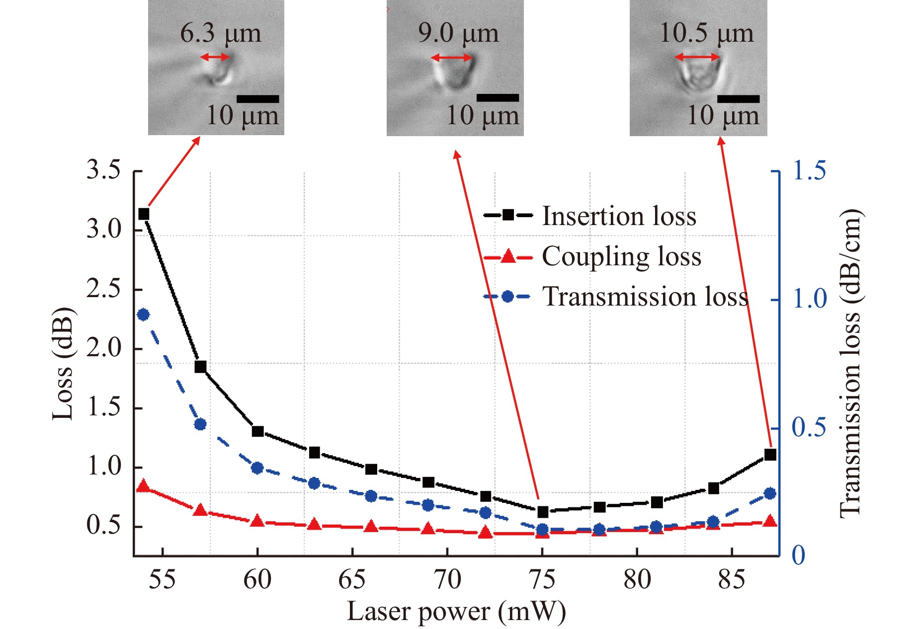
Fig. 3 Insertion, coupling, and transmission losses of the femtosecond laser inscribed with 2-cm waveguides under different laser powers.
A photonic lantern-mode (de)multiplexer was inscribed onto a 20 × 40 × 1 mm3 JGS2 glass substrate at a constant speed of 0.4 mm/s. The waveguides were scanned four times to improve and smooth the refractive index (RI). The fabricated waveguides have a cross-section with a diameter of 9.0 × 9.0 μm and a RI contrast of approximately 0.3%. The RI contrast was estimated by measuring the numerical aperture. Using an infrared CCD camera and high-precision moving stages, the divergence angle of the light from the femtosecond laser-inscribed waveguide can be measured. The RI of the waveguide can be calculated as follows: nsinθ=√n21−n22. Where n, n1, and n2 are the air, waveguide, and glass refractive indices, respectively, and θ is the measured divergence angle.
As shown in Fig. 1b, the mode multiplexer consists of three 20-mm waveguides. The middle waveguide, W2, is set as a 20-mm straight waveguide to generate the LP01 mode. Waveguide W1 of the LPa11 mode channel and waveguide W3 of the LPb11 mode channel are both composed of straight and bending waveguides. The three single-mode waveguides are arranged at the input in a linear array to match a 127-µm pitch fibre array. Through the 3D bending waveguides, the three cores were gradually brought together to form an equilateral triangular few-mode waveguide at the output. When the waveguide size is 9.0 µm and the spacing between the three waveguides is 6.0 µm, it exactly forms a small mode waveguide with a size of 15.0 µm, which matches a small mode fibre with a size of 14.8 µm. When both ends of the waveguide are fixed, waveguides W1 and W3 are contained in the inclined planes with angles of θ1 and θ3 to the horizontal plane, respectively.
The low-loss trajectories of the bending waveguides were designed to obey the following equation:
y=6hL5x5−15hL4x4+10hL3x3 (1) By rotating the 2D trajectories along the transmission direction axis at angle θ, a 3D waveguide can be obtained. The formula for this 3D waveguide is as follows:
(y2+z2)1/2=6hL5x5−15hL4x4+10hL3x3 (2) tanθ=zy (3) where L and h denote the track horizontal and vertical lengths, respectively, and x is the horizontal coordinate.
Next, all design parameters of the mode multiplexer can be determined using a formula that determines the length of the bending waveguides on both sides. See Section 2 of the Supplementary File for more details. The waveguide corresponding to LPb11 mode was composed of a 10.3-mm straight waveguide and a 9.7-mm bending waveguide. The waveguide corresponding to the LPa11 mode is composed of an 11.1-mm straight waveguide and an 8.9-mm bending waveguide. The fabrication time of each photonic-lantern mode (de)multiplexer was approximately 20 min, which means that multiple iterative processes can be performed in a short time.
The 3D laser inscribed photonic-lantern mode (de)multiplexer can convert a 1D single-mode waveguide array into a 2D few-mode distribution, based on which selective excitation of specific modes can be achieved. By launching the single-mode waveguide array with single-mode beams, the beam from the few-mode waveguide side of the photonic lantern was coupled to a 14.8-µm core diameter step-index few-mode fibre. An RI-matching fluid was used on both interfaces to reduce the Fresnel reflection. A single-mode beam was injected into the input ports of the multiplexer to obtain the output intensity profiles. As shown in Fig. 4a, the high-purity LPa11, LPb11, and LP01 modes can be clearly seen. Fig. 4b shows the intensity profiles from the output end of the FMF. The patterns from the FMF became slightly worse because of crosstalk in the FMF. However, they maintained a relatively good shape. High mode selectivity can reduce the complexity of electronic single processing. The insertion losses (including coupling losses) for the LPa11, LPb11, and LP01 modes were 1.14, 1.19, and 0.84 dB, respectively. The polarisation-dependent losses were less than 0.2 dB. Therefore, photonic-lantern mode (de)multiplexers are polarisation insensitive, which makes polarisation-division multiplexing applicable. Compared with femtosecond laser inscribed photonic-lantern mode (de)multiplexers with a traditional design, the performance of the devices designed in this study are greatly improved23,24.
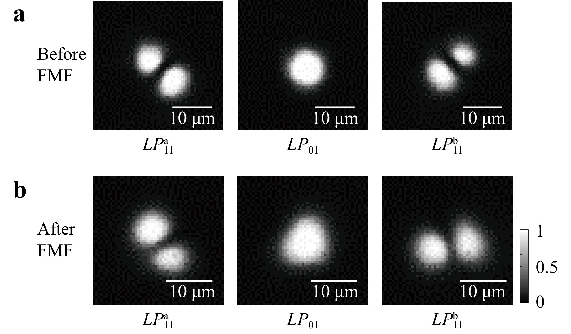
Fig. 4 Intensity profiles of the three-port photonic lantern mode (de)multiplexer outputs. a Intensity profiles of the LPa11, LPb11, and LP01 modes before FMF; b Intensity profiles of the LPa11, LPb11, and LP01 modes after FMF.
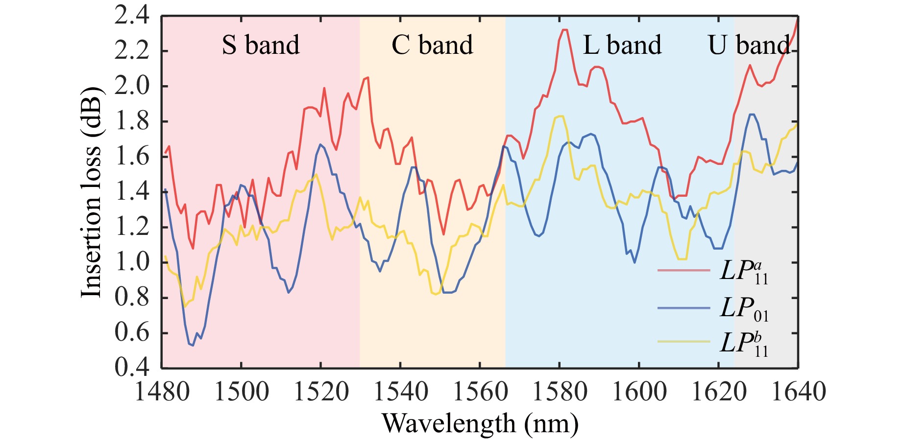
Furthermore, the spectral characteristics of the femtosecond laser-inscribed mode multiplexer with a wavelength range of 1480–1640 nm were measured. A tunable laser was used as a light source with a wavelength range of 1480–1640 nm. A power meter was used to record the output power after the laser beam was transmitted through a mode multiplexer. The wavelength interval between adjacent measurements was 1 nm. As shown in Fig. 5, each measurement curve comprises 161 points. The insertion losses ranged between 0.5–2.4 dB over the S + C + L bands with an average of 1.4 dB for all modes. The insertion loss fluctuation of all channels was less than 1.4 dB. Low insertion losses can increase the transmission length without optical amplification. The broad bandwidth enables the device to be scalable for ultrawide wavelength-division multiplexing (WDM) applications.
-
As shown in Fig. 6, we generated a 42-Gbaud/s QPSK signal by modulating a 1550-nm laser using an optical I/Q modulator. The signal was amplified using a C-band erbium-doped fibre amplifier (EDFA) after modulation. The signal was divided by a 50:50 coupler and then by two 33:33:33 couplers into six equal parts, each of which was delayed using a different fibre length to decorrelate the data sequence. These signals were transmitted through single mode fibres of 2, 1, 1, 1, 1, and 0.5 km, respectively, as sub-networks. Polarisation controllers (PCs) were used to alternately adjust the signal polarisation as x- and y-polarisation to meet the PBS requirements. Three PBSs, each of which coupled an x- and y-polarisation signal, were applied to realise polarisation multiplexing. The PBS insertion loss was approximately 0.8 dB. The three polarisation multiplexed signals are injected into a 127-µm pitch fibre array. The fibre array was placed on a high precision six-axis stage, aiming at the input ports of the photonic-lantern mode multiplexer, which was fixed on the chip placement stage. Three single-mode beams with polarisation-multiplexed signals were transformed into three LP modes, which were simultaneously outputted at the few-mode waveguide side as mode multiplexing. One side of the 860-m few-mode fibre was fixed on another six-axis stage to receive the output beam from the glass chip. The six multiplexed signals (LPa11x, LPa11y, LPb11x, LPb11y, LP01x, and LP01y) were then transmitted through an 860-m few-mode fibre. One PC was used to compensate for the polarisation state variation originating from the transmission of the 860-m few-mode fibre. The output side of the few-mode fibre was fixed on the third six-axis stage, aiming at the few-mode waveguide input side of the demultiplexer inside the second glass chip. The mode-multiplexed signals were demultiplexed and separated into specific single-mode output waveguides. Another fibre array placed on the fourth six-axis adjuster was used to receive the three single-mode outputs, which were polarisation demultiplexed by three additional reverse PBSs. An RI-matching liquid was used between the fibres and glass chips to eliminate Fresnel reflection and promote mode-field matching.
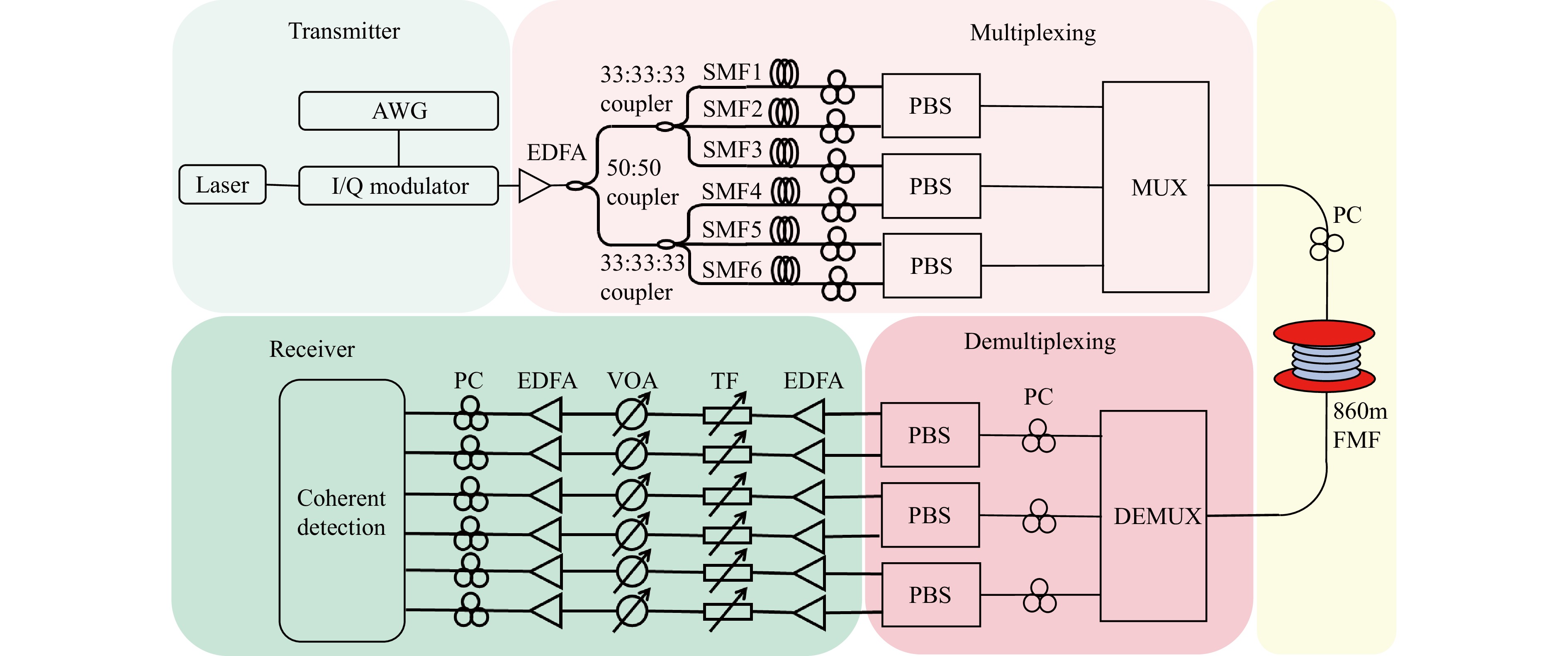
Fig. 6 Experimental setup of 6 × 6 mode- and polarization-division multiplexing optical transmission based on the ultrafast laser inscribed on-chip mode (de)multiplexer.
After demultiplexing, six single-mode beams with signals are sent to the receiver. The EDFAs were used to amplify the received signals. The amplified signals were filtered using tunable filters (TFs) to filter the selected wavelengths. Variable optical attenuators (VOAs) and EDFAs were used to adjust the optical signal-to-noise ratio (OSNR). The signals were coherently detected using a local oscillator light at the receiving end to obtain the QPSK electrical signals of the two polarisations. After sampling using an oscilloscope, the signals underwent offline digital signal processing, including I/Q orthogonalization, polarisation demultiplexing equalisation, frequency offset compensation, and phase offset compensation. The recovered QPSK baseband signal was then remapped into binary bits. Finally, a decoded binary pseudo-random sequence was used to calculate the bit error rate (BER).
-
The simplified 3 × 3 mode-division multiplexing and demultiplexing system with only two photonic-lantern mode (de)multiplexers and FMFs was built first. As shown in Fig. 7a, the crosstalk of the 3 × 3 mode-division multiplexing and demultiplexing system with 2-m FMF is −15.61 dB. When the system is applied with an 860-m FMF, as shown in Fig. 7b, the crosstalk increases to −12.60 dB. This increase is due to the lengthened FMF, which limits high-speed and long-distance signal transmission in the FMF system. Thus, an 860-m FMF was chosen to realise high-speed optical communication. Subsequently, a 6 × 6 mode and polarisation division multiplexing and demultiplexing system was built. As shown in Fig. 7c, d, the crosstalk with 2- and 860-m FMFs are −15.16 and −12.00 dB, respectively. The two systems have similar crosstalk, which means that polarisation-division multiplexing does not introduce serious crosstalk, and that polarisation- and mode-division multiplexing in the system are well combined.
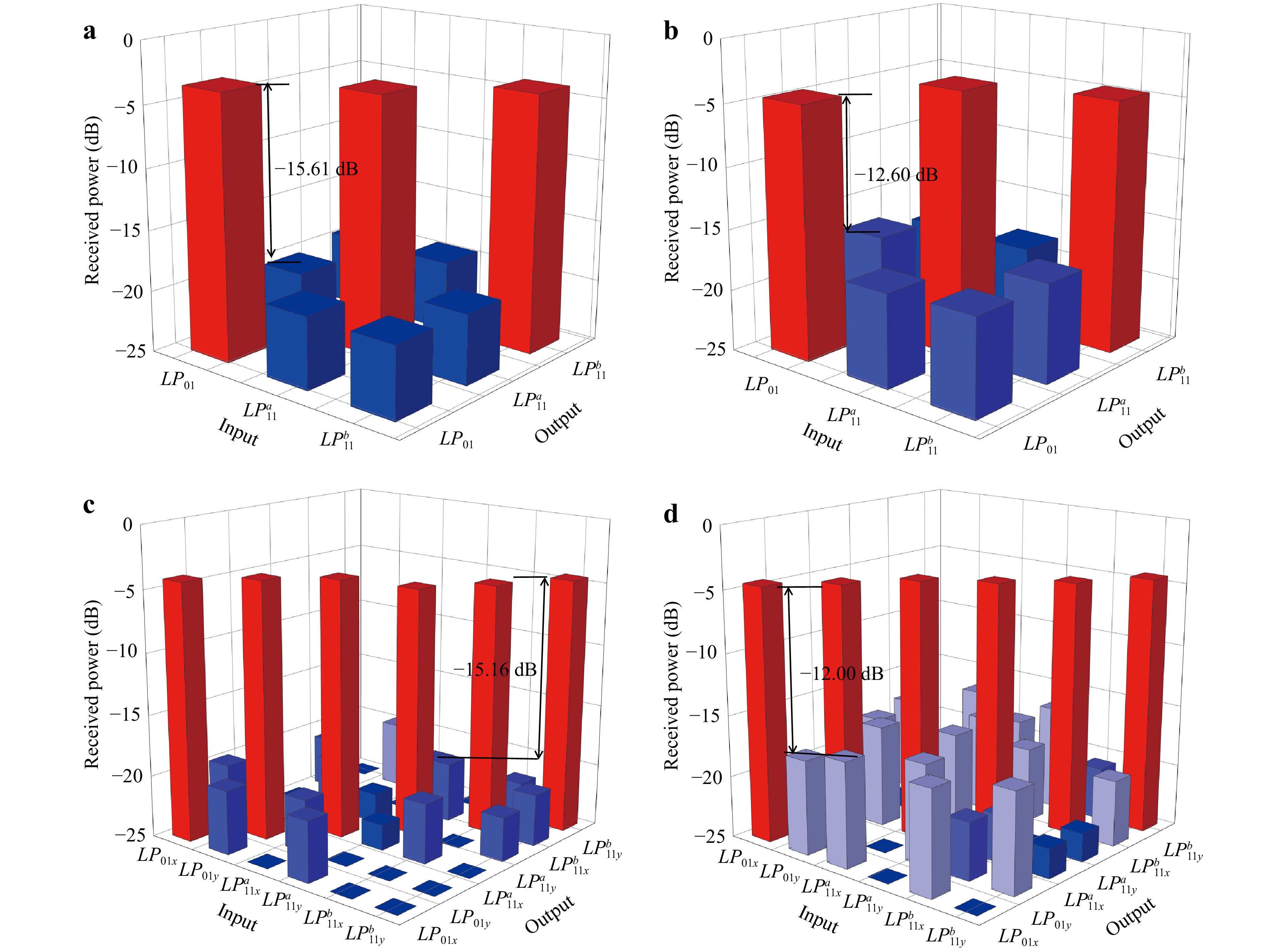
Fig. 7 Crosstalk of the 3 × 3 mode-division multiplexing and demultiplexing systems with a 2-m FMF and b 860-m FMF. Crosstalk of the 6 × 6 mode- and polarization-division multiplexing and demultiplexing systems with c 2-m FMF and d 860-m FMF.
Polarisation controllers were used to adjust the polarisation to ensure that the light of the LPa11 and LPb11 emerged at the output end. When the optical fibre length was 2 m, the disturbance from the optical fibre could be ignored, and the optical fibre transmission system remained stable in the long-term. When the fibre length increased to 860 m, the modes mixed with each other, which increased the crosstalk. After adjusting the light polarisation via the polarisation controllers to obtain the required mode output, the measured crosstalk increases from –15 to –12 dB. This result indicates that the fibre disturbance was not significant, which allowed us to complete the demonstration in a stable period. Multiple-input multiple-output digital signal processing (MIMO-DSP) is generally used for longer optical-fibre transmission experiments with severe crosstalk and disturbances.
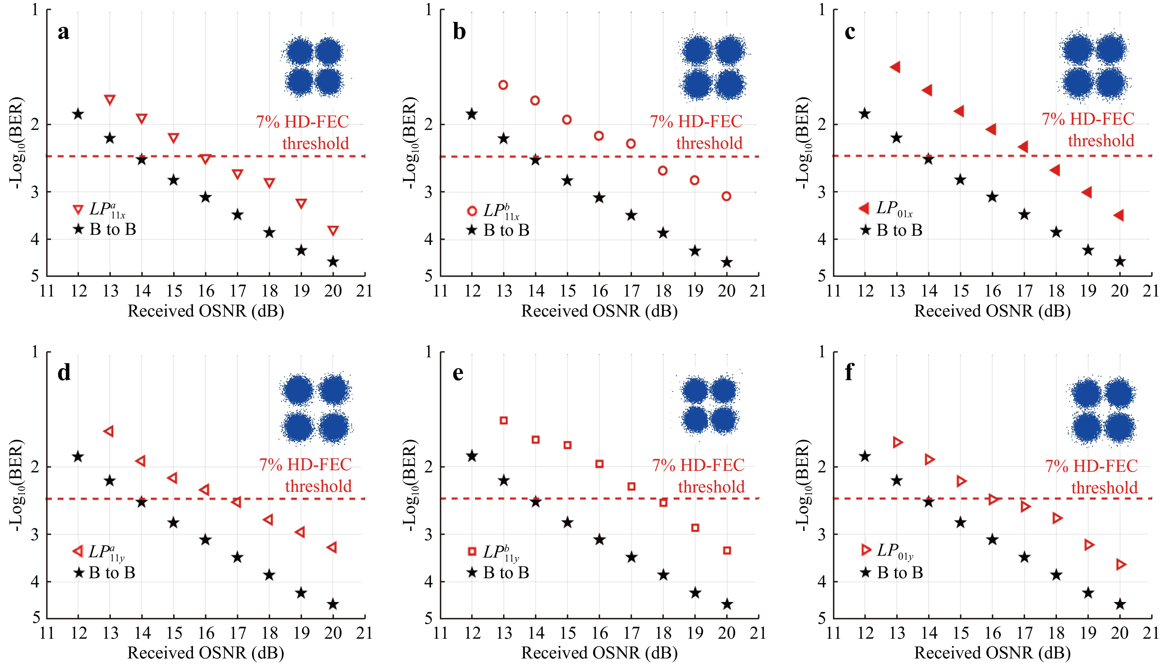
Finally, we measured the BER performance as a function of the received OSNR for 6 × 6 mode- and polarisation-division multiplexing transmission. The BER curves for the different modes (LPa11x, LPa11y, LPb11x, LPb11y, LP01x, and LP01y) are shown in Fig. 8a–f, respectively. Each figure shows the BER curve of the back-to-back system as reference. The difference between the two curves for the same BER value is the OSNR penalty, which represents the degree of signal deterioration. The observed OSNR penalties for different polarisations in the same LP mode are similar, indicating that the difference in polarisation does not affect the signal quality. The observed OSNR penalties of the LPb11 mode are 1.5 dB larger than those of the LPa11 and LP01 modes at a BER of 3.8 × 10⁻³ (7% hard-decision forward-error correction (FEC) threshold), which means that the quality of the LPb11 mode is worse, leading to a higher insertion loss. The uneven performance of the different modes was caused by structural asymmetry during processing. Although compensation is achieved by introducing coupling regions of different lengths, both exhibit better LP modes. However, the distribution of the two lobes of LPa11 was more uniform than that of LPb11, resulting in the better performance of the former. At the output end, the three waveguides comprising the few-mode waveguide have a standard equilateral triangular distribution, which limits their flexibility. In theory, compensatory optimisation can be achieved by adopting a more flexible waveguide distribution, which can achieve a higher-quality LP-mode excitation and solve the mode imbalance problem. The BER of all channels can easily reach below 3.8 × 10⁻³, which means that the 6 × 6 mode- and polarisation-division multiplexing and demultiplexing transmission in the 860-m FMF with 42 Gaud/s is reliable.
-
In summary, we comprehensively optimised the design of an ultrafast laser inscribed photonic-lantern mode (de)multiplexer by using trajectory asymmetry with uniform waveguides for superior performance and utilised it to achieve mode- and polarisation-division multiplexing and demultiplexing optical transmission. First, an optimised design using trajectory asymmetry with uniform waveguides is proposed. Based on uniform single-mode waveguides, consistent waveguide transmission and coupling losses 0.1 dB/cm and 0.2 dB/facet, respectively, at 1550 nm were obtained. Efficient mode excitation (LPa11, LPb11, and LP01) with average insertion losses as low as 1 dB at 1550 nm was achieved with mode-dependent losses of less than 0.3 dB by the trajectory-asymmetry design. It can be concluded that the proposed design exhibits better performed. Subsequently, we built a 3 × 3 mode-division multiplexing and demultiplexing system and 6 × 6 mode- and polarisation-division multiplexing and demultiplexing systems. All systems exhibit low insertion losses and crosstalk. Finally, we demonstrate a 6 × 6 mode- and polarisation-division multiplexing and demultiplexing system for high-speed optical communication in 860-m FMF. The BER measurement results show that high-speed optical communication is reliable and can play an important role in building optical interconnection links based on spatial multiplexing with an ultra-large communication capacity. Furthermore, a larger communication capacity can be realised with added mode channels, even by utilising more multiplexed light resources.
-
This work was supported by the National Natural Science Foundation of China (NSFC) (62125503, 62261160388), the Natural Science Foundation of Hubei Province of China (2023AFA028), and the Innovation Project of Optics Valley Laboratory (OVL2021BG004). The authors would like to thank the Optoelectronic Micro and Nano Fabrication and Characterizing Facility, Huazhong University of Science and Technology, for their support in device fabrication.




 DownLoad:



 DownLoad: