


-
Large-aperture interferometers are important and effective in the processing and inspection of large-aperture optical elements. They are based on the phase-shifting interferometry principles and utilize interference fringes generated by the interference between a large-aperture reference beam and a measurement beam to achieve functions such as surface profiling and wavefront-aberration detection of large-aperture components1–4. Therefore, they are key in optical precision processing, inspection, and manufacturing fields, and are ubiquitous in astronomical telescopes, semiconductor-wafer inspection systems, and inertial-confinement fusion devices5–9. The machining accuracy of processing extreme-parameters such as the large-aperture surface profiling, ultra-large curvature radius, and ultra-long focal length of optical elements, depends on the detection accuracy during the manufacturing process. Therefore, achieving accurate common baseline measurements for the multiple extreme-parameters of optical elements is crucial for enhancing the performance of high-end precision instruments. However, the measurement principles for the parameters of optical elements vary, and the results obtained from different instruments do not readily point toward a unified source, thus rendering it challenging to achieve common baseline measurements for extreme-parameters, such as large-apertures surface profiling, ultra-long focal lengths, and ultra-large curvature radii. Furthermore, the limited axial resolution and tomographic capability of optical inspection instruments arising from the diffraction limit significantly hinders the improvement of both the surface focusing accuracy and parameter-measurement precision. Therefore, achieving high-resolution precise focus on the surface of measured optical elements, resisting surface-roughness scattering can realize high-precision measurements of multiple extreme-parameters of optical elements10,11.
The most commonly used method for the high-precision surface-profiling measurement of large-aperture optical elements is interference, which entails Sub-aperture stitching12, the Ritchey–Common method13, and Fizeau interferometry14. Sub-aperture stitching allows one to measure large-aperture surface parameters without requiring a large-aperture reference lens. However, this method is characterized by low measurement efficiency and accuracy, thus rendering it difficult to satisfy the demands of high-precision surface-profiling measurements. The Ritchey–Common method requires highly precise standard spherical lens as reference lenses for detecting the surface profiles of large-aperture components. However, the manufacturing of large-aperture spherical standard lens is much difficult than that of large-aperture flat standard lens15. The Fizeau interferometer is widely used in high-precision surface-profiling measurement owing to its advantages of high measurement accuracy and speed, which arise from its common-path configuration. Phase shifting is a key step in Fizeau interferometry. However, in the large-aperture surface-profiling measurement, the conventional mechanical phase-shifting method presents issues such as immobility, thus rendering it challenging to satisfy the demands of high-precision surface-profiling measurements14,16–18. Hence, Katsuyuki Okada first used the tunable lasers as a light source for phase-shifting interferometers in 199019. In 2000, Peter de Groot proposed incorporating wavelength tuning into Fizeau interferometry20. This approach, known as wavelength-tuning phase shifting, enables both the reference and test lens to be stationary during the phase-shifting measurement process, thus significantly enhancing the mechanical stability of the instrument. Currently, the wavelength-tuning phase-shifting method has been applied to large-aperture interferometers2,15,21-23. However, existing wavelength-tunable lasers cannot simultaneously satisfy the requirements of high resolution and wide tuning range, thereby limiting the applicability of wavelength-tuning phase shifting and necessitating improvements to phase-shifting accuracy20,24–27. To overcome the fundamental limitations of existing large-aperture wavelength-tuning phase shifting, a team from the Beijing Institute of Technology proposed a mechanical phase-shifting method based on capacitor sensor monitoring for heavy-load reference lens28. This method yielded high-precision and high-stability mechanical phase shifting in large-aperture interferometric measurements.
To measure the ultra-long focal length of optical elements, three types of methods are primarily used: The first type is based on the principles of geometric optics imaging for focal-length measurement29. It utilizes the axial distance between the object and the image measured by the length measuring instrument, the magnification of the object image is obtained by digital image processing technology, and the focal length of the measured lens is obtained by the gaussian formula. However, this method presents a relatively low measurement accuracy of approximately 0.1%. Because of the diffraction limit at the focal point, further improving the measurement accuracy of this method is challenging. Struggling to overcome the high-resolution precise confocal bottleneck on the measured surface profiling. Due to the optical diffraction limit, axial resolution and confocal capabilities are difficult to significantly improve, thereby limiting the precision of surface focusing and parameter measurement. Additionally, there are challenges in overcoming the anti-surface scattering and anti-environmental disturbance measurement bottlenecks. It's difficult to measure samples with surface scattering characteristics, and measurement accuracy is severely affected by environmental factors such as airflow disturbances and ground vibrations; the second type is based on the Talbot effect and moiré fringe technology30. This method derives the focal length of the test lens from the changes in the angle or number of moiré fringes caused by the Talbot effect. It offers high measurement accuracy and high measurement efficiency. However, the accuracy of the focal length measurement by this method depends on the accuracy of the radius of curvature value, so it is necessary to obtain an accurate radius of curvature before performing the focal length measurement, and the high-precision measurement of the radius of curvature parameter is extremely challenging. So, the measurement process is cumbersome. The third type is based on interference techniques used for focal-length measurements31. In 2003, scholars from the Optical Sciences Center at the University of Arizona, in particular Brian DeBoo, proposed the interferometric fixed-focus Fresnel holography method. This method utilizes a Fizeau interferometer to accurately determine the focal and confocal point positions of a Fresnel holographic lenses, thereby achieving a precise focal-length measurement of the test lens32. This method successfully tested a lens with a focal length of 9 m and achieved a relative repeatability accuracy of 0.02%. This method partially satisfies the requirements for high-precision measurements. However, owing to the sensitivity of interference fringe angles to environmental factors, such as air disturbances, temperature variations, and ground vibrations, the interference fringe drift is significant, thus limiting the widespread application of such measurement methods in complex real-world environments.
Methods for measuring ultra-large curvature radii are typically classified into two categories: contact and noncontact measurement methods. Contact measurement methods include spherometers and fitting methods. The spherometer obtains the curvature radius of a test piece by measuring its sagittal height, whereas the fitting method involves scanning the surface of the test piece directly, obtaining the coordinates of several sampling points on the surface, and fitting the curvature radius of the test piece31. However, contact measurement methods typically generate scratches on the surface of the test piece during measurement and offer lower accuracy when measuring ultra-large curvature radii. Meanwhile, noncontact measurement methods primarily include geometric optics and interferometric fixed-focus measurement methods. Measurement methods based on geometric optics include Newton’s33 and shearing interference34 methods. However, owing to the diffraction limit, these methods have a lower focusing accuracy. Meanwhile, measurement methods based on interferometric fixed focus offer high measurement accuracy in the measurement of small curvature radii. In 1992, de Groot used Fizeau interferometry for curvature radius measurements35. However, owing to the long distance between the vertex and curvature center of the ultra-large curvature test piece, the measurement optical path was particularly susceptible to environmental factors. Therefore, the use of interferometry with compensating lenses, holographic gratings, and parallel crystal plates allows the measurement of ultra-large curvature radii. However, this method is not robust against environmental interference, and the calculation of interference fringes is easily disrupted by environmental factors, thus resulting in a lower accuracy36. What's more, the three-dimensional profile scanning method can be used to fit the curvature radius value by continuously scanning the three-dimensional surface morphology of the lens. However, the measurement process is too long and inefficient, and the method calculates the curvature radius by surface fitting, so the accuracy of the surface profile significantly affects the accuracy of the curvature radius parameter. In summary, high-precision and high-efficient large-aperture surface profiling can be achieved using the principles of Fizeau interferometry. Currently, measurement methods for parameters such as the focal length and curvature radius of optical elements are constrained by the diffraction limit, which renders it difficult to overcome the bottleneck of high-resolution precise focusing on the measured surface, thus resulting in low focusing accuracy. Moreover, they are significantly affected by environmental factors such as airflow disturbances and ground vibrations.
Hence, this study proposes a high-precision large-aperture laser differential confocal interferometric measurement method. By organically integrating the large-aperture interferometric measurement path with the laser differential confocal detection path, this method achieves high-resolution, anti-scattering, and anti-interference measurements of multiple parameters under common baseline measurement conditions. Mechanical phase-shifting of large-aperture, high-precision, heavy-load reference lenses has enabled high-precision measurement of surface profiles of large-diameter optical elements; Precise focusing of laser differential confocal has enabled high-precision measurement of parameters such as ultra-long focal length and ultra-large curvature radius of optical elements. We optimized the design of the transmitted wavefront of the large-aperture laser differential confocal measurement system and the aberrant aberration of the imaging system. Experimental validation of large-aperture surface profiling, ultra-long focal lengths and ultra-large radii of curvature has also been carried out. An uncertainty analysis is then performed, and the full paper is finally summarized. This study provides an accurate, efficient, and versatile detection method for large-aperture optical elements processing and optical systems assembly.
-
The principle of the large-aperture laser differential confocal-interferometric measurement system (LLDCIMS) is illustrated in Fig. 1. We use the Fizeau horizontal interferometric light path configuration,which has several advantages, including a simple structure, fewer accessories, and good applicability and flexibility for testing. Light from a point source passes through a large-aperture beam-expanding system (LBES), which includes a small-aperture collimator (SAC), a beam expander (BE), and a large-aperture collimator (LAC), and is then transformed into a large-aperture parallel beam. A portion of this beam serves as the reference beam, which is reflected by the back surface of the reference lens (RL) and then passes through the beam-expansion system, reflected by beam splitter1 (BS1), transmitted by beam splitter2 (BS2), and reflected by mirror R2 before entering the imaging system. This serves as the reference beam for the rotating ground glass. Another portion of the light serves as the measurement beam, which is transmitted through the reference lens and enters the tested lens (TL). After being reflected by the tested lens, it passes through the reference lens and beam-expansion system, and is then reflected by beam splitter1 (BS1), transmitted by beam splitter2 (BS2), and reflected by mirror R2 before entering the imaging system. This serves as the measurement beam for the rotating ground glass (RG). The reference and measurement beams interfere with the ground glass of the imaging module, and the interference pattern is recorded by the interference charge-coupled device (CCD) after passing through the imaging lens. During the large-aperture interference measurement process, a high-precision phase-shifting function is derived using a large-aperture mechanical phase-shifting system (LAMPS) with a heavy-load reference lens. The air-bearing slider (ABS) supports the large-aperture heavy-load reference lens and its precise adjustment mechanism (PAM) to counteract gravity loads. Phase shifting is driven by a three-channel piezoelectric ceramics (PZT) drive structure via the piezoelectric effect, whereas the elastic deformation of the flexible hinge (FH) enables the gapless micro-displacement of the heavy-load reference lens mechanical phase-shifting system. This setup enables the high-precision measurement of the surface profiling parameters of large-aperture optical elements.

Fig. 1 Principle diagram of large-aperture differential confocal-interferometric measurement system. a large-aperture laser differential confocal-interferometric measurement path; b large-aperture beam-expansion system; c large-aperture mechanical phase-shifting system; d laser differential confocal signal-processing module; e interference signal-processing module; f ultra-long focal length; g convex spherical ultra-large curvature radius; h concave spherical ultra-large curvature radius; i concave spherical interference; j convex spherical interference.
Replacing the reference lens with a large-aperture spherical standard lens enables the measurement of the surface profile, ultra-large curvature radius, and ultra-long focal length of large-diameter spherical optical elements. Acquisition of laser differential confocal signals through virtual pinholes (VP) for measurement of optical component parameters. Moreover, using a system-switching device (SSD) allows one to achieve common baseline measurements of multiple parameters, such as the surface profile, curvature radius/ultra-large curvature radius, and focal length/ultralong focal length of optical elements with small apertures.
-
When using the large-aperture differential confocal-interferometric measurement system for large-aperture surface-profiling measurements, the tested lens is placed in the path of the collimated beam behind the reference lens. The interference pattern of the reference beam reflected from the reference lens and the measurement beam reflected from the surface of the tested lens can be expressed as
$$ I(x,y,{t_n}) = {I_d}(x,y) + {I_a}(x,y)\cos [\varphi (x,y) + \delta ({t_n})] $$ (1) where, Id(x,y) represents the background beam intensity of the interference fringes, Ia(x,y) the amplitude of the interference fringes, φ(x,y) = 2kw(x,y) the wavefront phase distribution of the reflected measurement beam from the tested lens, and δ(tn) the phase shift introduced by the reference lens. Specifically, x and y denote the horizontal and vertical coordinates of the pixel points of the i phase-shifting interferogram, respectively, and tn denotes the time required for each phase-shift step.
Additionally, δ(tn) is obtained using the mechanical phase shifter of the heavy-load reference lens, as shown in Fig. 1c. Designing a mechanical structure that combines high-frequency response and high-resolution flexible hinges (FH) with piezoelectric ceramics allows the mechanical phase-shifting system to achieve sub-nanometer-level phase shifting without gaps in the reference lens. Meanwhile, integrating a high-stability, low-ripple piezoelectric ceramic drive power supply and a phase-shifting mechanism in the circuit control allows the mechanical phase-shifting system to achieve high-resolution and low-error phase shifting. By establishing a spatial in-situ monitoring model that combines high-precision, high-resolution capacitive sensors (HCS) with phase control, the interference measurement system can achieve a sub-nanometer-level precision spatial translation of the reference lens. Meanwhile, establishing calibration algorithms for the pitch and yaw errors of the reference lens during mechanical phase shifting allows the system to suppresses phase-shifting errors. Ultimately, high-precision measurement of δ(tn) is achieved in the interference measurement system.
The large-aperture mechanical phase-shifting system model is depicted in Fig. 2, which can be simplified as a mass–spring-damping second-order system28. Under the action of the force at the input end, the deformation is generated at the output end by the interaction of seven straight circular flexible hinges A-G. Based on the equilibrium of the forces in the x, y, and z directions as well as the equilibrium of the forces Fx, Fy, and Fz and the moments Mx, My, and Mz of each hinge, the mechanical phase-shifting actuator of the heavy-load reference lens is designed. The large-aperture mechanical phase-shifting system is driven by a piezoelectric ceramic. If the input displacement is denoted as x, then the output displacement of the mechanical phase-shifting guide rail, denoted as pd, can be expressed by the motion differential equation established based on the large-aperture mechanical phase-shifting system model as follows
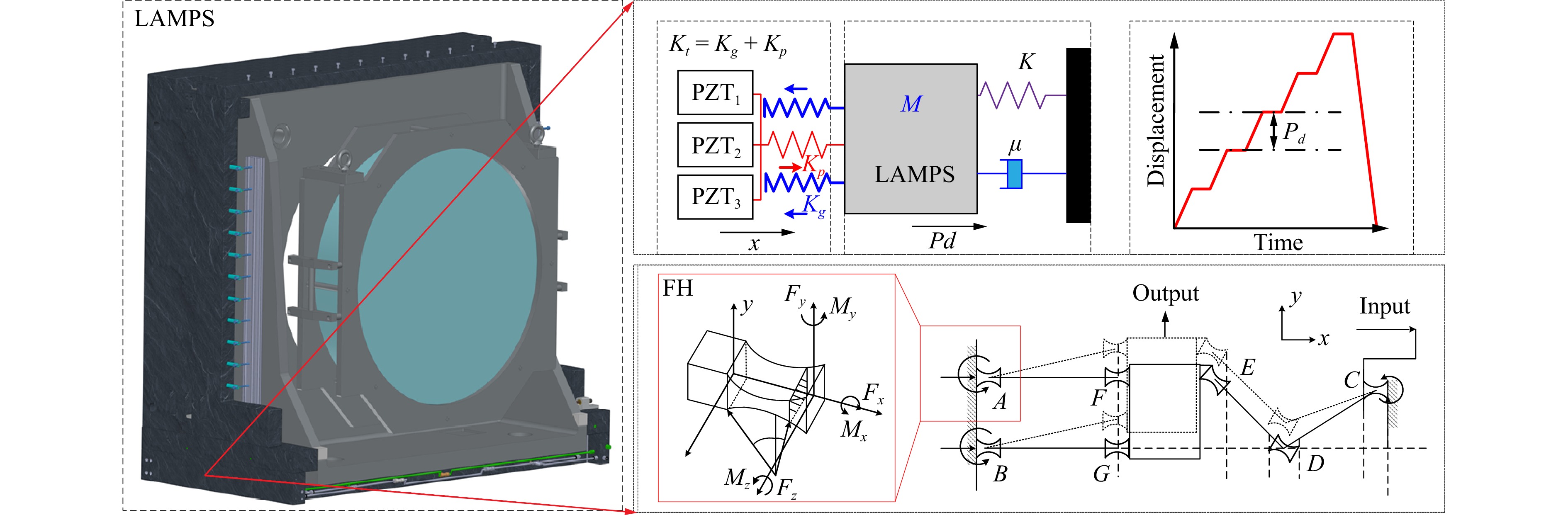
Fig. 2 Principle of the large-aperture mechanical phase-shifting system model
$$ M{\ddot p_d} + \mu {\dot p_d} + \left( {{K_t} + K} \right){p_d} = {K_t}x $$ (2) where K is the stiffness of the mechanical phase-shifting guide rail for the heavy-load reference lens, M the total weight of the mechanical phase-shifting system, µ the damping coefficient, and Kt the stiffness of the mechanical phase-shifting transmission mechanism.
Based on the system transfer function, the open-loop transfer function of a large-aperture mechanical phase-shifting system can be derived as follows
$$ G\left( s \right) = \frac{{\alpha {K_v}{K_s}\omega _n^2}}{{\left( {{R_i}{C_p}s + 1} \right)\left( {{s^2} + 2\xi {\omega _n}s + \omega _n^2} \right)}} $$ (3) where $ {K_s} = {{{K_t}}}/({{K + {K_t}}}) $ is the amplification factor, Kv the amplification ratio of the direct current high-voltage power supply, $ {\omega _n} = \sqrt {({{K + {K_t}}})/{M}} $ the undamped natural frequency of the system, $ \xi = {\mu }/{{2M{\omega _n}}} $ the damping ratio of the system, Ri the internal resistance of the PZT drive power supply, and Cp the equivalent capacitance of the PZT.
Using the open-loop transfer function of the large-aperture mechanical phase-shifting system allows one to achieve high-precision and high-stability control of the heavy-load reference lens and thus the actual value of δ(tn). The relationship between the displacement amount pd of the reference lens obtained via the mechanical phase shifting of the heavy-load reference lens and the phase shift amount δ(tn) introduced by the reference lens can be expressed as3
$$ \delta \left( {{t_n}} \right) = {p_d}\frac{{4{\text π} }}{\lambda } $$ (4) where λ represents the wavelength of the laser light source.
Subsequently, a five-step equal-step phase-shifting algorithm is employed, as shown in Fig. 1e. By obtaining five interferograms with phase shifts of δ(tn) = 0, π/2, π, 3π/2, and 2π, the phase distribution φ(x,y) can be extracted as follows
$$ \varphi \left( {x,y} \right) = \arctan \left[ {\frac{{2\left( {{I_4} - {I_2}} \right)}}{{2{I_3} - {I_1} - {I_5}}}} \right] $$ (5) Next, phase unwrapping is performed, followed by Zernike fitting and removal processing, thus resulting in the actual surface profiling of the tested lens.
-
When utilizing the large-aperture differential confocal-interferometric measurement system (LDCMS) for ultra-long focal-length measurements, RL is the large-aperture spherical reference lens, and the tested lens is placed in the collimated beam path between the large-aperture spherical RL and the large-aperture collimating lens, as illustrated in Fig. 3.
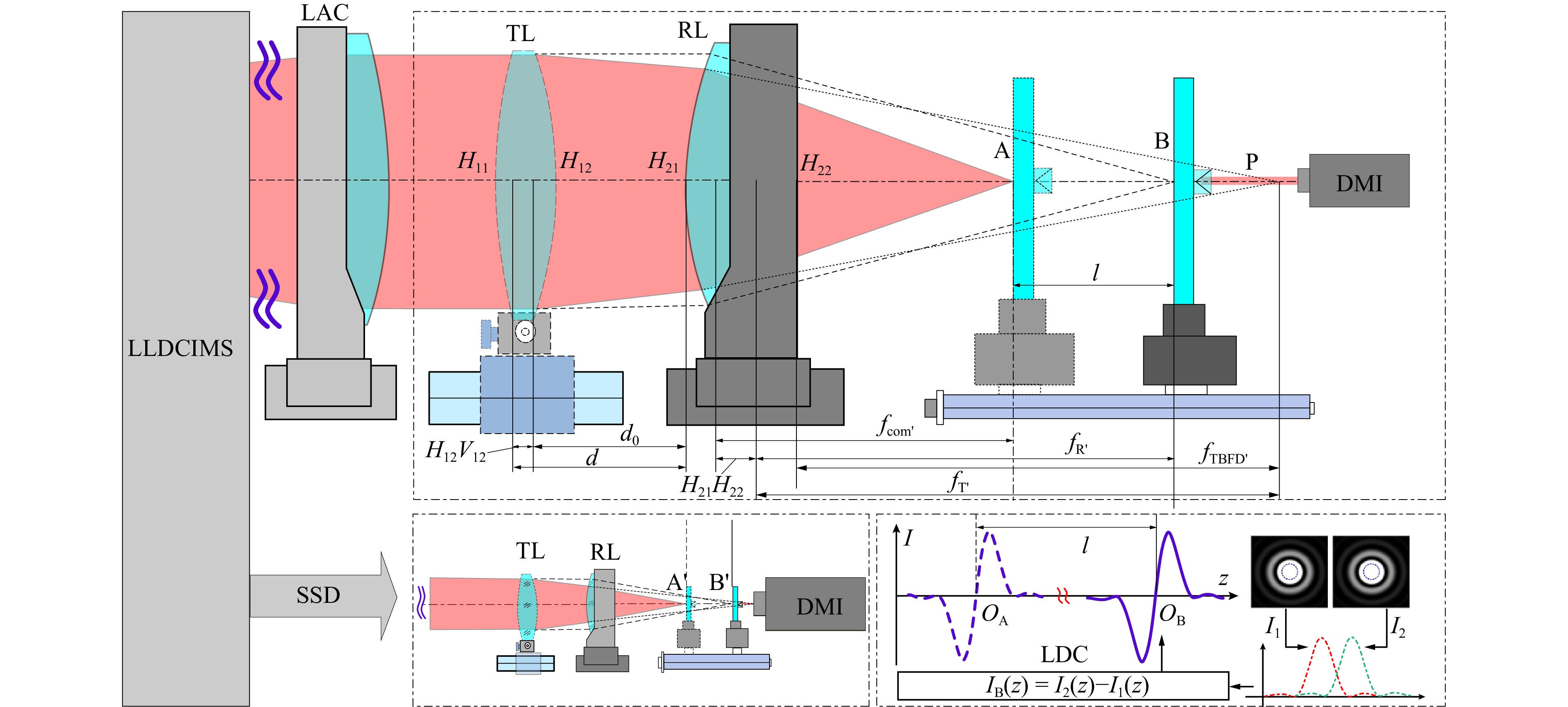
Fig. 3 Measurement principle of laser differential confocal ultra-long focal length
By precisely correlating the zero points QB of the axial intensity response curves IB(u, uM) of the differential confocal system with the combined focal point B. Then, remove the tested lens and move the reflector to reach A to obtain the differential confocal response signal IA(u, uM), the distance l of the change in focal position with/without the tested lens with an XL-80 Renishaw interferometric (DMI). Subsequently, based on the focal length fR′ of the reference lens and the mirror separation distance d0, the posterior vertex focal distance fTBFD′ of the tested lens is obtained. Utilizing the curvature radius of the tested lens, the vertex focal distance fTBFD′ is converted into the focal length fT′, thereby achieving the measurement of ultra-long focal length lenses37.
Based on geometric imaging theory, the effective focal length fcom′ of the combined lens system, the focal length fT′ of the tested lens, the focal length fR′ of the reference lens, the posterior vertex focal distance fTBFD′ of the tested lens, and the axial distance d from the principal plane of the test lens image side to the principal plane of the reference lens object side, one can calculate the effective focal length value fT′ of the tested lens by converting from the posterior vertex focal distance fTBFD′ of the tested lens as follows
$$\begin{split} {f_T}' = \;&d - {f_R}' + \frac{{{f_R}{'^2}}}{l} = {d_0} - {f_R}' + \frac{{{f_R}{'^2}}}{l} +\\& \frac{{r{}_{12}{b_1}}}{{{n_1}(r{}_{12} - {r_{11}}) + ({n_1} - 1){b_1}}} + \frac{{r{}_{12}{b_1}}}{{{n_1}(r{}_{12} - {r_{11}}) + ({n_1} - 1){b_1}}} \end{split}$$ (6) where b1 is the center thickness of the tested lens, n1 is the refractive index of the material, and r11 and r12 are the radii of curvature of the left and right surfaces, respectively.
Small-aperture tested lenses can be placed in the measurement beam path of small optical elements. This measurement method is consistent with that for a large-aperture ultra-long focal length. The laser differential confocal signals are precisely focused at points A′ and B′ to achieve accurate focusing, thus enabling the measurement of small-aperture tested lenses with ultra-long focal lengths.
-
When utilizing the large-aperture differential confocal-interferometric measurement system (LDCMS) for the ultra-large curvature radius, RL is the large-aperture spherical reference lens, and the tested lens is positioned in the converging light path of the large-aperture spherical reference lens, as illustrated in Fig.4. After passing through the large-aperture spherical reference lens, the light converges to cat's eye position of the measured lens, i.e., A. The differential confocal light intensity response curve IA(u, uM) at the cat’s eye position of the measured surface is used to accurately determine the focus of the cat’s eye position. Subsequently, the tested lens is shifted such that the measurement beam is reflected off the surface of the tested lens and converges at position D the back surface of the reference lens. At this point, surface D the back surface of the reference lens is focused precisely using the differential confocal-intensity response curve IC(u, uM) at position C. Finally, the position difference LT between points A and C is measured using a DMI, and the curvature radius r of the tested lens is obtained using ray-tracing algorithms in conjunction with the posterior vertex focal length fRBFD′ of the reference lens38.
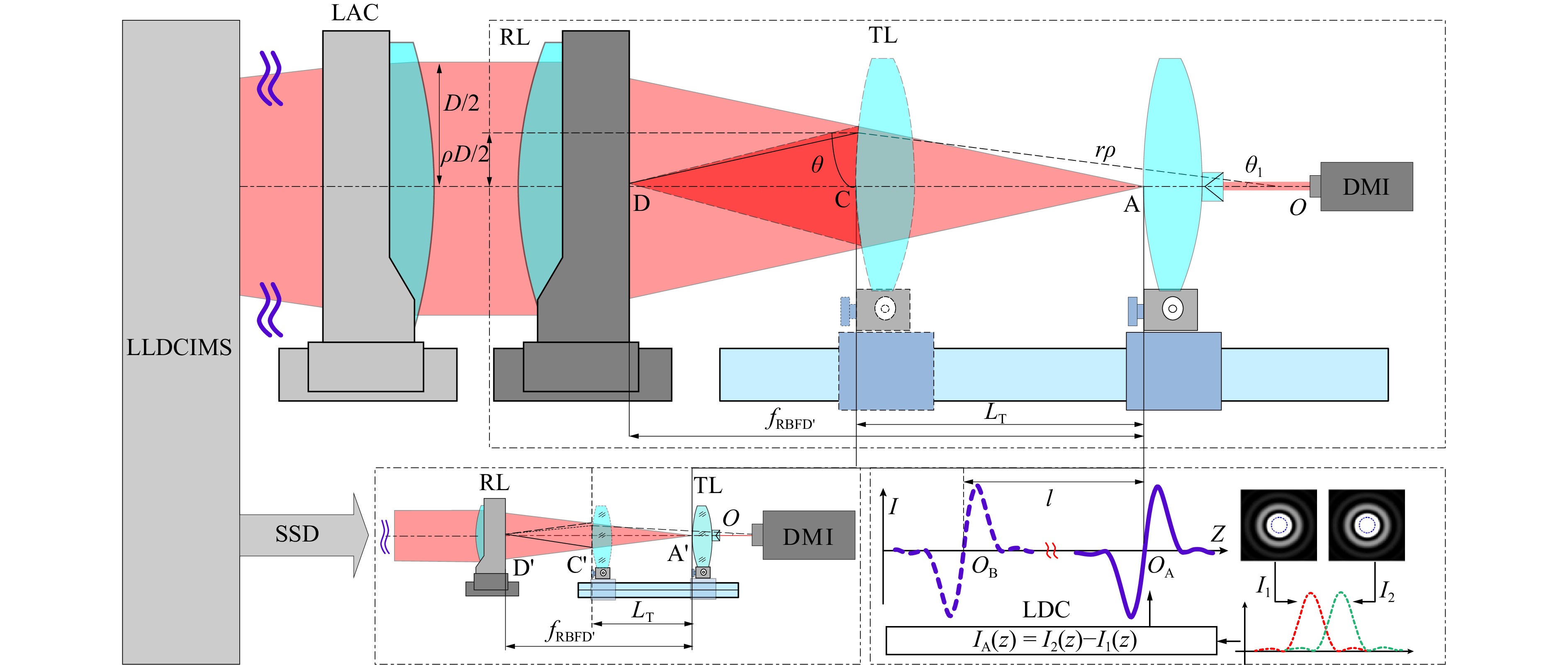
Fig. 4 Measurement principle of laser differential confocal ultra-large curvature radius
The zero-crossing points Q1 and Q2 of the laser differential confocal-intensity response curves IA(u, uM) accurately correspond to cat's eye position A of the tested lens. The difference in the positions of the tested lens at points A and C, which is denoted as LT here, can be precisely measured using a DMI.
$$ \left\{ \begin{gathered} \theta = \arctan \left( {\frac{{\rho D}}{{2{f_{RBFD}}^\prime }}} \right) \\ \tan\frac{{{\theta _1}}}{2} = \frac{{2{f_{RBFD}}^\prime {r_\rho }\left( {1 - \cos{\theta _1}} \right)}}{{\rho D\left[ {{L_T} - {r_\rho }\left( {1 - \cos{\theta _1}} \right)} \right]}} \\ {r_\rho } = \frac{{\left( {{f_{RBFD}}^\prime - {L_T}} \right)\sin \left( {\theta - 2{\theta _1}} \right)}}{{\sin \left( {\theta - {\theta _1}} \right) - \sin \left( {\theta - 2{\theta _1}} \right)}} \\ \end{gathered} \right. $$ (7) Here, D is the aperture of the reference lens, ρ the normalized aperture of the beam, θ the angle between the outgoing light rays from the reference lens and the optical axis of the reference lens. The curvature radius of the tested lens, which was calculated based on imaging from point A to point D by the light ray at aperture ρ, is denoted as rρ. Meanwhile, θ1 represents the angle between rρ and the optical axis m of the reference lens.
The curvature radius value r of the tested lens can be expressed as
$$ r = \frac{{\displaystyle\int_0^1 {2{\text π} \rho {r_\rho }d\rho } }}{{\displaystyle\int_0^1 {2{\text π} \rho d\rho } }} = 2\displaystyle\int_0^1 {\rho {r_\rho }d\rho } $$ (8) Small-diameter tested lenses can be placed on small-aperture measurement optical paths. This measurement method is consistent with that for a large-aperture curvature radius. By precisely focusing at points A' and C' based on laser differential confocal signals, one can accurately measure small-diameter tested lenses with an ultra-large curvature radius.
In summary, the large-aperture laser differential confocal-interferometric measurement system can achieve high-precision, multiple parameters, common baseline measurement for optical elements of large, medium, and small diameters.
-
Based on the schematic diagram of the measurement system shown in Fig. 1, a large-aperture laser differential confocal-interferometric measurement system was designed and developed, as shown in Fig. 5.
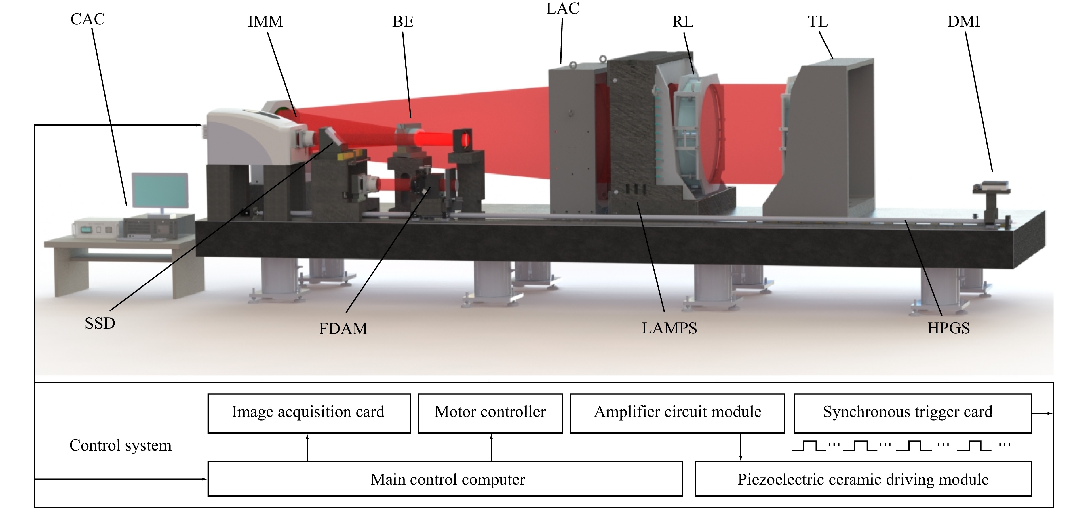
Fig. 5 Large-aperture laser differential confocal-interferometric measurement system
This system consists of several main components: the interferometer main machine (IMM), which is used to complete the measurement data acquisition, and the controller and computer (CAC); the large-aperture beam-expanding system, which is used to expand the point light source into a parallel beam with an aperture of 820 mm; the heavy-load reference lens mechanical phase-shifting mechanism, which is used to realize the mechanical phase-shifting function of the heavy-load reference lens; the small-aperture multiparameter measurement system, which is used to realize the multiparameter measurement of small-aperture optical elements, including a precision five-dimensional adjustment mechanism (FDAM) for adjusting the posture of the tested lens, a precision rail screw mechanism (HPGS) for the precise positioning of the tested lens, and an XL-80 Renishaw interferometric displacement measurement mechanism (DMI) for obtaining the displacement of the tested lens; and the main control system, which is used to control the entire system and process the acquired data, including the processing of interference signals and laser differential confocal signals. In addition, the mainframe of the interferometric measurement system, the large-aperture beam-expanding system, the large-aperture precision-adjustment mechanism, and the mechanical phase-shifting mechanism are designed on the same air-floating vibration isolation instrument base. Switching measurements of different apertures can be achieved through a conversion mechanism to satisfy the requirements of multiple extreme-parameters common baseline measurements.
The optical system is the most crucial component of a large-aperture laser differential confocal interferometric measurement system. The precision of an optical system determines the measurement accuracy of the entire instrument. To satisfy the requirements for high-precision measurements, an optical system for a large-aperture laser differential confocal-interferometric system was designed, as shown in Fig. 6. To ensure the stability of interference fringes while satisfying the spatial and temporal coherence requirements of the light source, a He-Ne laser light source with the following parameters was selected: wavelength of 632.8 nm, power stability of <2.5%; spot diameter of 0.6 mm and divergence angle of 1.4 mrad. The combined focal length of the beam-expander system, fZ, was 8155 mm.
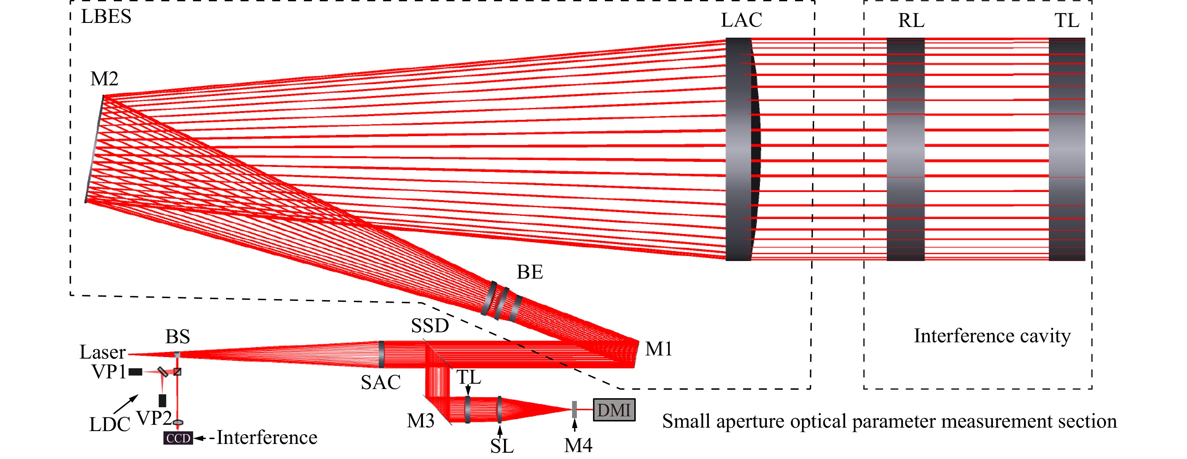
Fig. 6 Optical system of large-aperture laser differential confocal-interferometric system
The design results of the optical system are shown in Fig.7. For the large-aperture laser differential confocal interferometric system, the transmitted wavefront of the system with a PV value of 0.0074λ for the transmitted wavefront was adopted. The distortion aberration of the imaging system was less than 0.011%, and the MTF of the system was > 0.6@22lp/mm. The spot radius of the system is 0.3 μm, which was smaller than the Airy disk radius of 2.2 μm. The pixel size of the differential confocal signal acquisition camera was 8.3 μm × 8.3 μm, which met the measurement requirements for differential confocal ultra-long focal lengths and ultra-large radii of curvature.
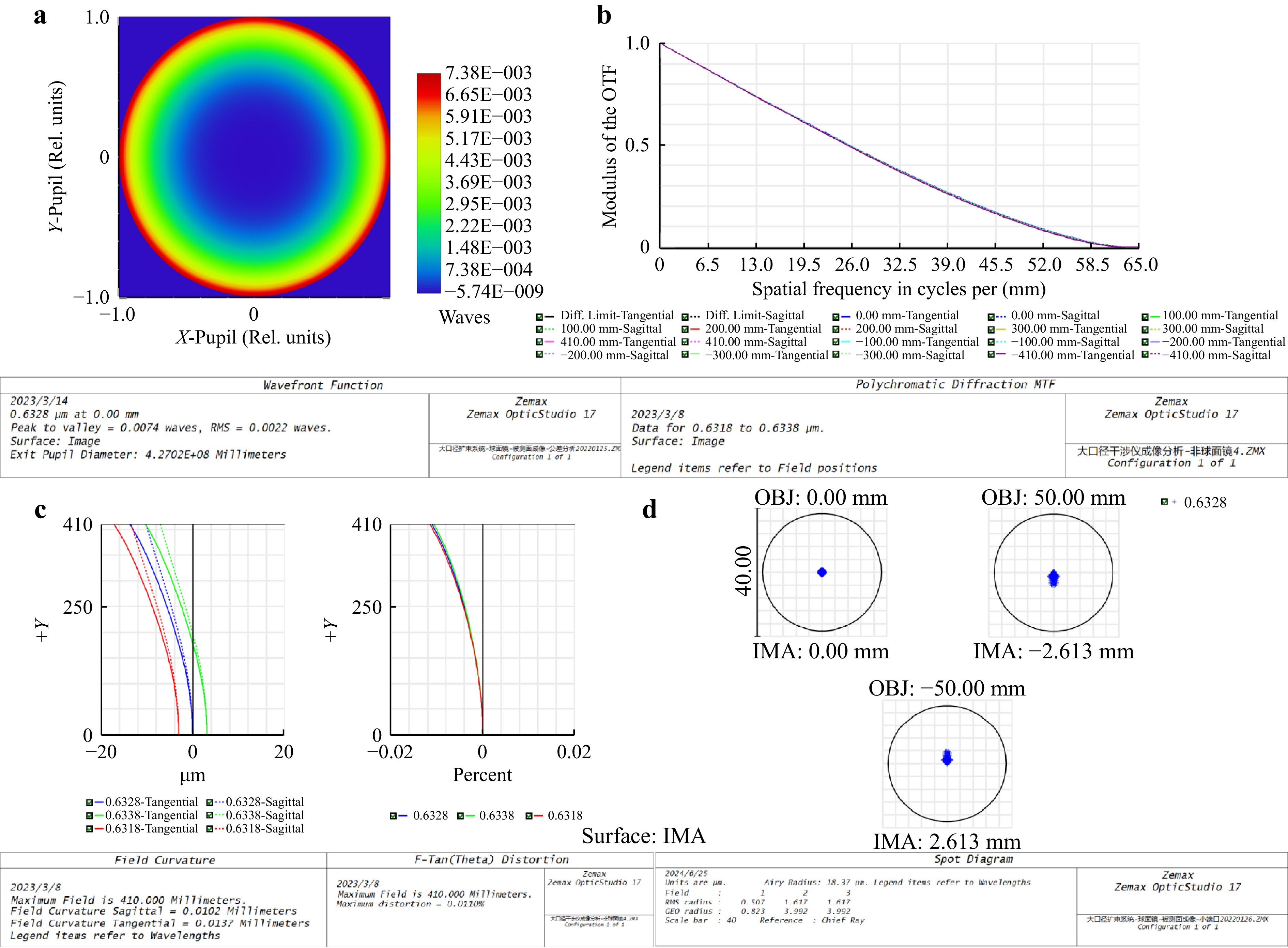
Fig. 7 Design results of large-aperture laser differential confocal-interferometric measurement optical system. (a) the transmitted wavefront of the system; (b) the MTF of the system. (c) The distortion aberration system. (d) The spot radius of the system.
In a large-aperture laser differential confocal-interferometric measurement system, the hardware components, under the coordination of the host computer and measurement control software, perform functions such as phase-shifting drive control, high-resolution interferometric image acquisition, precise surface-profile computation, phase-shifting monitoring signal acquisition, pose signal decoupling and computation, tilt-error separation compensation, phase-shifting interferometric calculation and processing, and differential confocal signal acquisition and computation.
-
Based on the constructed large-aperture laser differential confocal-interferometric measurement system, the tested lens with effective apertures of ϕ800 mm were used for measurement, and the surface quality was characterized by the average values of wavefront PV and RMS. The measured surface profiles are shown in Fig. 8. Additionally, 100 experiments were conducted, which showed minimal variation in the PV and RMS values of the tested lens, thus indicating good measurement repeatability. The average PV obtained from 100 measurements was 46.0nm, with an average RMS of 8.00 nm, the PV standard deviation of 100 measurements is σPV =0.00220λ=1.4 nm and the RMS standard deviationis σRMS = 0.00101λ = 0.64 nm.
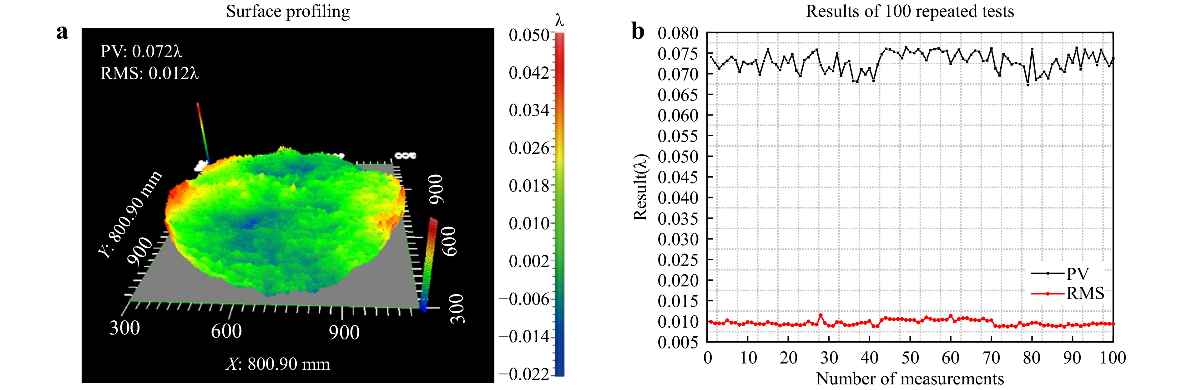
Fig. 8 Results of test experiment
-
On the constructed large-aperture laser confocal-interference measurement system, experiments were conducted to validate the feasibility of the proposed experiments were conducted to validate the feasibility of the proposed measurement methods using the test lens with a focal-length of 10452.21mm and an aperture of 100 mm, for an ultra-long focal length lens and the test lens with an ultra-large curvature radius of −14792.38 mm and an aperture of 100 mm.
The experimental setup and results are presented in Fig. 9. As depicted in Fig. 9a, for the 10452.21mm ultra-long focal length lens, the standard deviation is 2.15 mm and a relative standard deviation is 0.019%. Based on the measurement results shown in Fig. 9b, for the tested lens with a curvature radius of −14792.38 mm, the standard deviation is 0.55 mm and a relative standard deviation is 0.0036%.
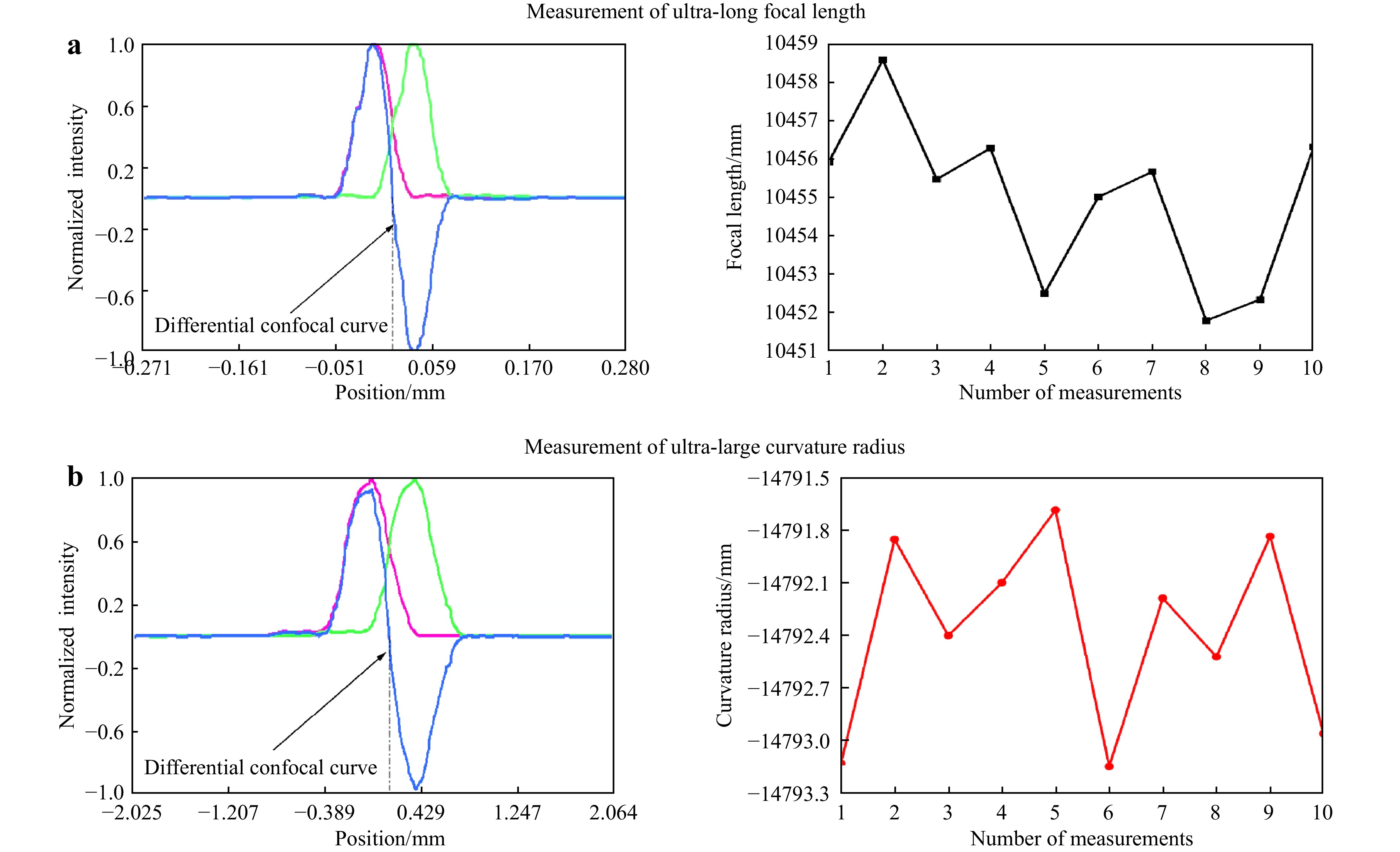
Fig. 9 Experimental results of ultra-long focal length and ultra-large curvature radius measurement.
-
(1) Optical Quality of Large-Aperture Interferometer
The optical quality of the large-aperture interferometer, which is based on the results of the cavity calibrations of the reference lens and the tested lens performed by the Standardization and Testing Center of the Laser Fusion Research Center, is the standard deviation of the measurement result expressed as
$$ {u_{B1}} = \left( {0.073\lambda + 0.002\lambda \times 3} \right)/3 = 0.0265\lambda $$ (9) (2) Errors Introduced by Mechanical Phase Shifting
The mechanical phase-shifting errors include calibration and nonlinear errors. Using nonlinear voltage drive and compensation methods can reduce the mechanical phase-shifting error to 2.01 × 10⁻⁴ rad. This introduces a standard deviation of λ/500 for the wavefront measurement error. The standard deviation is
$$ {u_{B2}} = 0.002\lambda $$ (10) (3) Detection Error of Photodetector CCD and Quantization Error of Interference Image
The CCD detection errors can be classified into two categories. The first is the nonlinearity of the response at each point on the target surface of the CCD. The other is the unevenness in the geometric distribution of the CCD target surface, which can introduce errors during the conversion to a digital image. The standard deviation of the introduced wavefront error is λ/10039.
$$ {u_{B3}} = 0.01\lambda $$ (11) (5) Effect of Stray Fringes
Owing to the addition of stray light from the reflection of various optical surfaces in the optical system, the standard deviation of the introduced wavefront error due to stray fringes is λ/800.
$$ {u_{B4}} = 0.00125\lambda $$ (12) (6) Stability of Light Source
The frequency stability of the laser affects the accuracy of the interferometer test. The standard deviation of the light source is
$$ {u_{B5}} = 0.002\lambda $$ (13) (7) Calculation of Uncertainty
The combined uncertainty (u) is calculated using the root-sum-square method by combining the various components of uA and uB as follows
$$ U = k{\left[ {\sum {u_i^2} } \right]^{1/2}} = k \times {\left[ {u_{B1}^2 + u_{B2}^2 + u_{B3}^2 + u_{B4}^2 + u_{B5}^2} \right]^{1/2}} $$ (14) Therefore, according to the uncertainty analysis, it can be seen that the expanded uncertainty of the large-aperture interferometer based on the mechanical phase shift of the heavy-load reference lens is λ/29, that is, 22.0 nm. The current interferometer surface profiling accuracy is λ/10, so the achieved accuracy of 22.0 nm is advanced compared with the accuracy of other optical metrology designs for similar optical elements. We have effectively suppressed the phase shift error and improved the measurement accuracy of the system by using a high-precision, heavy-load reference lens mechanical phase shift method. In addition, the detection error of the photodetector CCD and the quantization error of the interference image are the main sources of error. This error can be reduced by replacing the device and optimizing the algorithm to improve the accuracy of the system.
-
(1) Uncertainty caused by d0
According to the literature40, that the relative measurement error of the axial space is less than 0.02%. Therefore, the stand uncertainty of d0 can be described based on a uniform distribution as follows
$$ u\left( {{d_0}} \right) = \frac{{0.02\% \times {d_0}}}{{\sqrt 3 }} $$ (15) (2) Uncertainty caused by fR′
Based on uncertainty analysis, the combined stand uncertainty of fR′ can be expressed as1
$$ u\left( {f_R^{'}} \right) = \sqrt {{{\left( {\frac{{{\sigma _{axial}}}}{{\sqrt 3 }}} \right)}^2} + {{\left( {\frac{{{\sigma _{offset}}}}{{\sqrt 3 }}} \right)}^2} + 4\left[ {{{\left( {\frac{{{\sigma _{DMI}}}}{{\sqrt 3 }}} \right)}^2} + {{\left( {\frac{{{\sigma _{\Delta L1}}}}{{\sqrt {20} }}} \right)}^2}} \right]} $$ (16) where σoffset is the detector offset error, σaxial the alignment error, and σDMI the distance measurement error. These errors are discussed in detail in Ref. 40. In addition, σΔL1 is the stand uncertainty of ΔL1 from 10 measurements.
(3) Uncertainty caused by l
The causes of uncertainty in l are the errors caused by two detectors with different offsets, the distance measurement error, and the axis alignment error.
$$ u\left( l \right) = \sqrt {{{\left( {\frac{{{\sigma _M}}}{{\sqrt 3 }}} \right)}^2} + {{\left( {\frac{{{\sigma _{\alpha ,\beta }}}}{{\sqrt 3 }}} \right)}^2} + {{\left( {\frac{{{\sigma _L}}}{{\sqrt 3 }}} \right)}^2} + {\sigma ^2}_l} $$ (17) where σα,β is the measurement error caused by misalignments between axes; σL is the measurement error of the distance between positions A and B, which can be measured using an XL-80 Renishaw interferometer; and σM is the error caused by two detectors with different offsets.
Considering the effects of the three uncertainties, i.e., u(fR′), u(d0), and u(l), the total combined stand uncertainty u(fT′) is
$$ {u_{rel}}(f_T^{'}) = \frac{{\sqrt {{{\left[ {\dfrac{{\partial f_T^{'}}}{{\partial {d_0}}}u\left( {{d_0}} \right)} \right]}^2} + {{\left[ {\dfrac{{\partial f_T^{'}}}{{\partial f_R^{'}}}u\left( {f_R^{'}} \right)} \right]}^2} + {{\left[ {\dfrac{{\partial f_T^{'}}}{{\partial l}}u\left( l \right)} \right]}^2}} }}{{f_T^{'}}} \times 100\% $$ (18) Based on the above uncertainty components, the uncertainty analysis of the lens with focal length of 10452.21 mm has a related standard uncertainty of 0.034%, and the experimental measurement results have a relative standard deviation of 0.019%. Thus, the result of the uncertainty analysis is identical to that of the experiments.
-
(1) Uncertainty component u(L1)
Considering the uncertainty components of ultra-large curvature radius, the combined uncertainty u(L1) can be obtained as follows
$$ u\left( {{L_1}} \right) = \sqrt {u\left( {{L_1}} \right)_{axial}^2 + u{{\left( {{L_1}} \right)}^2}_{of f set} + u{{\left( {{L_1}} \right)}^2}_{DMI} + u{{\left( {{L_1}} \right)}^2}_{\sigma 1}} $$ (19) where u(L1)axial is the uncertainty caused by axial-misalignment errors, u(L1)offset the uncertainty caused by two detectors with different offsets, u(L1)DMI the uncertainty caused by position-measurement errors, and u(L1)σ1 the uncertainty observed from repeated measurements.
(2) Uncertainty component u(L2)
The uncertainty u(L2) due to the position difference L2 of reflector can be written as
$$ u\left( {{L_2}} \right) = \sqrt {\frac{1}{2}\left[ {{{\left( {\frac{{{\sigma _{axial}}}}{{\sqrt 3 }}} \right)}^2} + {{\left( {\frac{{{\sigma _{of f set}}}}{{\sqrt 3 }}} \right)}^2} + {{\left( {\frac{{{\sigma _{DMI}}}}{{\sqrt 3 }}} \right)}^2}} \right] + {{\left( {\frac{{{\sigma _{L2}}}}{{\sqrt {10} }}} \right)}^2}} $$ (20) where σoffset is the error caused by two detectors with different offsets, σaxial the alignment error, and σDMI the distance measurement error. These errors are discussed in detail in Ref. 38. In addition, σL2 is the standard deviation of ΔL2 from the careful adjustments and experiments.
Assuming the aforementioned uncertainty components of the radius R for the tested lens measurements are independent of each other, the relative combined measurement uncertainty in large-aperture laser differential confocal interferometry can be obtained using Eq. 22 as follows
$$ {u_{rel}}(R) = \frac{{\sqrt {{{\left[ {{c_1}u\left( {{L_1}} \right)} \right]}^2} + {{\left[ {{c_2}u\left( {{L_2}} \right)} \right]}^2}} }}{R} \times 100\% $$ (21) Where c1 and c2 are the uncertainty transfer coefficients of L1 and L2, respectively.
Based on the above uncertainty components, the relative uncertainty of large-aperture laser differential confocal interferometry is expected to be less than 0.0038% for a tested lens with a radius of approximately −14792.38 mm and a relative standard deviation of 0.0036%. The results of the uncertainty analysis are in good agreement with the experimental results.
-
This study proposes a research on a high-precision large-aperture laser differential confocal-interferometric measurement method. Addressing the limitations of long diffraction focal depth and susceptibility to environmental disturbances by employing laser confocal precise-focusing technology to achieve precise focusing for large-diameter optical elements. By implementing air-floating support for the gravity unloading of a heavy-load reference lens and spatial in-situ monitoring using capacitive sensors, large-aperture mechanical phase-shifting interference measurements were realized. By integrating laser confocal-interference fusion, the bottleneck in the comprehensive measurement of multiple parameters with a common baseline can be overcome. A high-precision measurement method based on large-aperture laser confocal interference was proposed, which achieved, for the first time, high-precision comprehensive measurements of multiple parameters for optical elements with large, medium, and small apertures using the same instrument. Experimental results indicated that based on 100 repeated measurements of large-aperture surface profiles, the mean PV accuracy was 46.0 nm, with a system uncertainty is 22.0 nm. For the measurement of a 10452.21 mm ultra-long focal length, the relative standard deviation was 0.019%, whereas for the measurement of a −14792.38 mm ultra-large curvature radius, the relative standard deviation was 0.0036%. This system achieved high-precision, comprehensive measurements of multiple parameters for large-aperture interference based on the mechanical phase shifting of the heavy-load reference lens, thus providing an advantageous approach for improving the detection and processing accuracy of large-diameter optical elements.
-
This research is supported by National Natural Science Foundation Joint Fund Integrated Project (No. U22A6006), National Key scientific research instrument Development Project of the National Natural Science Foundation of China (No. 52327806).
Research on high-precision large-aperture laser differential confocal-interferometric optical element multi-parameter measurement method
- Light: Advanced Manufacturing , Article number: (2024)
- Received: 09 March 2024
- Revised: 21 August 2024
- Accepted: 23 August 2024 Published online: 16 October 2024
doi: https://doi.org/10.37188/lam.2024.047
Abstract: To fulfill the requirements of high-precision common baseline measurement for multiple parameters, such as surface profiling and the curvature radius of large-aperture optical elements on the same instrument, this paper proposes a research on a high-precision large-aperture laser differential confocal-interferometric measurement method. This method is based on the principle of laser differential confocal combined with interferometry. It utilizes a Galilean double-reflection collimation system to generate well large-aperture collimated beams and employs mechanical phase-shifting technology for large-aperture and heavy-load reference lenses to overcome the flaws of existing large-aperture wavelength-tuning phase shifting technology in theory, thus achieving high-precision and high-stable phase-shifting interference in large-aperture surface profiling measurements. By utilizing the laser differential confocal method with anti-scattering and anti-interference properties, high-precision common baseline measurements are achieved for the multiple-parameter of optical elements such as ultra-long focal lengths and ultra-large curvature radii. The measurements of large-aperture surface profiles, the mean PV was 46.0 nm. For the ultra-long focal length, the relative standard deviation was 0.019%, whereas for the ultra-large curvature radius, the relative standard deviation was 0.0036%. This method enables high-precision, high-stable, and high-efficient common baseline measurements for the multiple parameters of optical elements with large, medium, and small apertures thereby providing an effective technical approach for improving the detection and machining precision of optical elements.
Rights and permissions
Open Access This article is licensed under a Creative Commons Attribution 4.0 International License, which permits use, sharing, adaptation, distribution and reproduction in any medium or format, as long as you give appropriate credit to the original author(s) and the source, provide a link to the Creative Commons license, and indicate if changes were made. The images or other third party material in this article are included in the article′s Creative Commons license, unless indicated otherwise in a credit line to the material. If material is not included in the article′s Creative Commons license and your intended use is not permitted by statutory regulation or exceeds the permitted use, you will need to obtain permission directly from the copyright holder. To view a copy of this license, visit http://creativecommons.org/licenses/by/4.0/.

 DownLoad: