


HTML
-
Terahertz (THz) beam shaping1 attracts more and more attention in the last decade. Among the structures obtained by the optical beam shaping, a large niche is occupied by cylindrical vector2 and vortex3 beams with inhomogeneous polarisation states and optical vortices with phase singularities4. The formation of such beams in the THz range becomes a hot topic in current research, as they are gaining much attention due to their amazing properties, such as high efficiency coupling ability with bare metal wires5. THz beams are involved in numerous applications, such as imaging6, telecommunications7, and material characterization8. There are also other tasks, such as toroidal moment generation9 and waveguide particle acceleration10.
The ability of THz radiation to excite rotational and vibrational degrees of freedom of atoms and substances11, 12 makes it possible to utilise THz beams to precisely drive certain molecular states. For example, longitudinally polarised THz beams13 can be used as efficient particle accelerators14, 10. Due to the possibility of achieving orbital angular momentum (OAM) with a large number of eigenstates15−17, the involvement of THz vortex beams are considered as a perspective approach to increase the bandwidth of communication channels7, 18, 19. Recently, super-resolution pump-probe imaging with THz vortex beam was used to observe saturable absorption behaviour in bilayer graphene20. THz beam shaping is also of high interest for imaging applications: for example, the use of THz Bessel beams shows better contrast and resolution of the image6.
Quite wide variety of transverse beam modes has been experimentally demonstrated in the THz range: Laguerre-Gaussian THz beams21, Bessel-Gaussian THz beams22, 23, Airy THz beams24, circular polarisation Airy THz beams25, and even more complex transverse beam modes. However, a significantly smaller proportion of publications on vector and vortex beams are associated with ultrafast pulsed broadband radiation. Among the latter, the various specific polarisation states and the spiral wavefront structure are presented at a limited range of spectral components that comprise the wave packet.
Ultrashort pulses possessing a homogeneous vortex structure across broad spectral range are known as broadband uniformly topologically charged (BUTCH)26 beams and belong to the class of topological charge dispersion-free beams27−32. Such beams in THz frequency range are already finding unique applications, e.g., as sensors of magnetic properties33, or as a carrier in the information encoding34−37. The formation of these beams is a complicated task due to the necessity to provide a homogeneous cyclic phase swirl for a large number of dispersive spectral components. These gradually increasing applications of such beams have prompted a demand for further development of techniques for their formation and assessment, which led to the appearance of this work.
We decided to divide the material into two interconnected manuscripts with numbered titles containing a common part “Design of broadband terahertz vector and vortex beams”. This paper is the first part of this set of two interrelated papers. It contains an exhaustive review of the state-of-the-art approaches for broadband THz vortex and vector beam shaping, and comparative analysis of their pros and cons. It includes the results available to date from various research groups. In contrast, Part II38, reports on the development and application of our proposed holographic approach for the analysis of the ultrabroadband THz wavefront evolution during it propagation through the partially-achromatic elements of designed beam shapers. Ultrafast spatially inhomogeneous wave trains are known to demonstrate strong spatio-temporal couplings39, 40 and their comprehensive assessment is usually a nontrivial task41, 42 due to the necessity of their characterisation in multiple modalities. At the same time, such diversity opens up a large scope for the formation of new beam types43−46 and expands the potential of their applications. In the second part of this set of papers38, we will focus on the capabilities of THz pulse time-domain holography (THz PTDH)47−50 to describe and visualise the formation and propagation of such beams. For a better understanding of the possibilities offered by a detailed analysis of the beam properties, in the second paper of this paired set we consider few examples of the broadband performance of the THz vortex beams.
As far as this article is concerned, it presents not only a detailed review, systematisation, and comparison of existing and potential approaches to THz broadband vector and vortex beam shaping. We begin with an analysis of existing and promising components applicable as modulators for the formation of such beams. Finally, we aggregate the available approaches to the manufacturing of advanced beam shapers and other possible mechanisms for the tailoring of vector or/and vortex broadband radiation in THz frequency range.
-
While reviewing the current methods for vortex beams formation in the THz range, we can not help mentioning the existing review papers3, 51, 52, describing most of the approaches proposed and developed to date. Unfortunately, despite the vast range of methods for vortex beam formation considered therein, none of them are focused on the broadband achromatic vortex beams, thus making this study useful and unique.
Several research groups3, 53 suggest dividing all the existing methods of vortex beams formation into two main categories: passive and active THz vortex beam shaping. Under the passive approach, the vortex beams are formed from pre-generated smooth wavefront THz pulses with Gaussian transverse profile of amplitude, while under the active one the authors assume direct THz vortex generation upon nonlinear downconversion from infrared radiation. We fully support this division, and it remains valid for the subset of broadband beams. However, we would suggest addressing these categories as THz beam shaping and direct THz beam generation (Fig. 1) to avoid ambiguity with terminology accepted in metasurface design, where the term “active” implies the possibility of tuning, as a rule, by an external field. Turning to the previously available scientific literature on THz vector and vortex beams formation, we should mention that, since most holographic methods of vortex beam formation (e.g. diffractive optical elements, computer-synthesised holograms) target to monochromatic radiation only they are outside of the scope of our consideration.
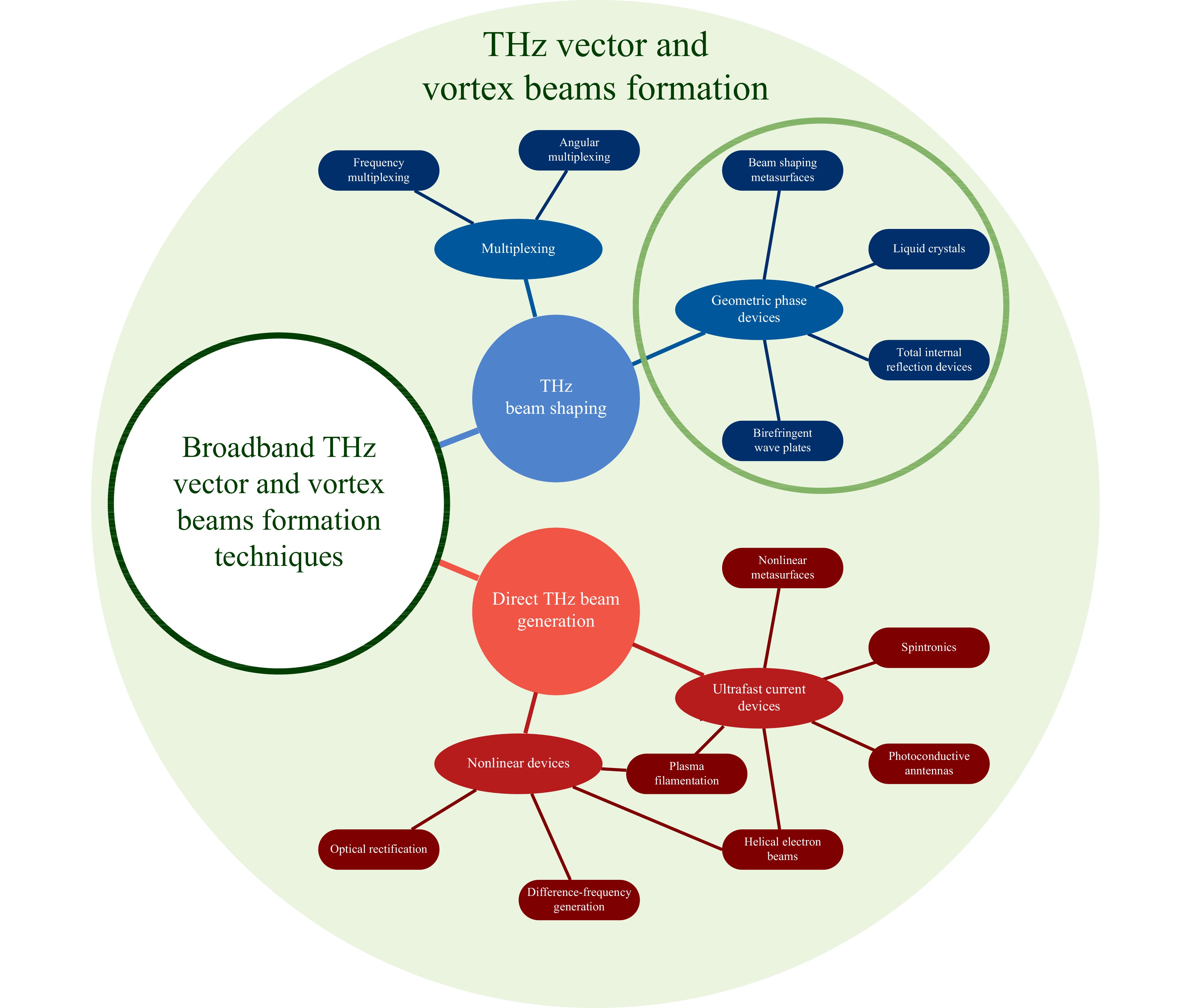
Fig. 1 Schematic art view of different techniques of THz broadband vector and vortex beam formation.
Among the categories of broadband optical vortex formation methods considered in Fig. 1, historically, passive approaches for the visible frequency range were the first to be developed. Subsequently, they were adapted for the THz frequency range. We note that most of the techniques for obtaining broadband THz vortex and vector beams demonstrated to date implement a geometric method of phase transformation by rotating the polarisation vector. Let us look at the underlying principles of these techniques through a historical background.
In the early 1930s, it was shown that a circularly polarised paraxial beam transfers a spin angular momentum (SAM)
$ {S} $ 54 associated with the polarisation of a wave capable of imparting rotation to anisotropic optical elements. Later, in the 1990s, Allen et al.55, 56 demonstrated a paraxial light beam carrying orbital angular momentum (OAM)$\mathsf{L} $ which is directly associated with optical vortices. These momenta are conserved for the paraxial beam spreading in any direction in the free space or in a homogeneous and isotropic transparent medium. In their seminal research, Ciattoni et al.57 proved that in free space, the sum of the projections of these momenta in the direction of propagation$ {z} $ is an invariant of the wave motion, and hence the balance of the total angular momentum flux is conserved:$ {{S}_{z}}+{{L}_{z}} = 1 $ 58. However, optically anisotropic and inhomogeneous media intercouple both beam polarisation and wavefront shape, thus, consequently, can change both SAM and OAM, independently59. The physics behind the effect is based on a quantum phenomenon known as the geometric phase of Pancharatnam-Berry60, 61. This principle is fundamental for optical devices that use full SAM-OAM conversion59, 62. The origin of this term is associated with the geometric transformation of the polarisation state defining the corresponding cyclic adiabatic process, which appears to be an evolution path mapped on the surface of the polarisation Poincaré sphere63. Therefore, an arbitrary wavefront and phase reshaping will correspond to half of the solid angle enclosed by the path of a continuous sequence of polarisation transformations, which is determined only by the geometry of the polarisation path64. Polarisation elements, based on this principle, are commonly named Pancharatnam-Berry optical elements (PBOE) and are not limited to helical waves shaping but can be extended to unbound wavefront control. Another feature of PBOE is subject to phase modification by means of only a space-variant retarder orientation and is therefore insensitive to wavelength variation65, which provides the basis for a practically valuable approach to the design of achromatic phase optical elements66 suitable for passive formation of broadband THz vector and vortex beams. Among all PBOE, the most widely used are: q-devices made with birefringent wave plates67, total internal reflection principle68, 69, liquid crystal analogues70, 71, and metasurfaces72−75.Another THz broadband vortex beam shaping approach is the adaptation of the multiplexing techniques developed for other ranges of the electromagnetic spectrum to the THz frequency range. These techniques can be roughly divided into angular multiplexing28, 45, 76−80 and frequency multiplexing81−89 and, as a rule, use off-axis and on-axis schemes, respectively. Generally, these techniques are less energy-efficient; therefore, to date, they have not received widespread use, due to the acute lack of powerful THz sources. And today in the THz frequency range we can single out only one computational work in angular80 and few in frequency87, 88 multiplexing.
In the case of direct generation of THz broadband vortices and vector beams, the principle of the geometric phase is also fundamental. However, it is also supplemented by the specific features of the conversion mechanisms from ultrashort femtosecond pump pulses into THz radiation. Direct generation approaches can be roughly divided into nonlinear and ultrafast current-based devices. The first category includes optical rectification5, 90−94, difference-frequency generation95−98, helical electron beams99, 100, and plasma filamentation101−108. Helical electron beams and plasma filamentation on their inherent mechanisms of downconversion are also related to the second group where they supplement the photoconductive antennas98, 109−111, spintronic emitters112 and nonlinear metasurfaces113, as presented in Fig. 1. It should be noted that the approach to plasma generation of high-intensity THz radiation in liquid114, 115 is currently showing great potential. Such THz source may open a new direction in the design of vortex and vector beam generators.
In this work, our attention will be focused on “passive” THz broadband beam shaping techniques, among which the geometric phase approach highlighted with a green circle in Fig. 1 is the most promising to controlling the beam structure in a broad spectrum.
-
The principle of the geometric phase discussed in this paper is based on the use of the so-called q-plates, so we will first consider the principle of their operation. In accordance with the generally accepted definition, q-plate is an inhomogeneous anisotropic medium, which optical axis angle
$ \theta $ in the$ (x,y) $ plane exhibits a uniform distribution over the whole surface defined in this coordinate system and is described by the following relation64:$ \theta\left(\psi\right) = q\psi +{{\theta }_{0}} $ , where$ \psi = \text{arctan}\left( y/ x\right) $ is the azimuthal angle in the$ (x,y) $ plane,$ {q} $ is an integer or semi-integer constant and$ {{\theta }_{0}} $ denotes the angle between “zeroth” optical axis position at$ \left( \psi = 0 \right) $ and$ x $ -axis and may take an arbitrary value. The q-plate got its title due to the fact that the polarisation of a passing wave is experiencing a continuous sequence of spatial turns which is determined by the value$ {q} $ 116, 59. Various approaches have been proposed for the construction of such devices117−121.The analysis of the balance of SAM and OAM for each photon in a circularly polarised wave (
$ {{S}_{z}} = \pm \hslash $ , where$ \pm $ denotes circularity handedness and$ \hslash $ is a reduced Planck constant) passing through this q-plate demonstrates a mutual transformation of momenta when the light inverts its polarisation helicity from$ +\hslash $ to$ -\hslash $ and therefore the resulting OAM arises, while the overall variation of total angular momentum suffered by the photon passing the q-plate being62:$ \Delta {{J}_{z}} = \left( 2q-1 \right)\hslash -\hslash = 2\hslash \left( q-1 \right) $ . The q-plate performs a wavefront tailoring with phase given by$ \varphi = \pm 2q\psi $ , resulting in a helical vortex structure with topological charge$ \mathsf{L} = \pm 2q $ . The handedness of the vortex phase helicity and a sign of the topological charge are controlled by the polarisation state of the input field.The manufacture of the q-plate does not always reproduce the smooth rotation of the optical axis. The design of the discrete q-plate can be composed of a set of sectors with individual inclinations of the optical axis. Thus, it is possible to implement the constant phase delay in each sector to obtain the resulting phase shift throughout the plate
$ \varphi = 2\pi \mathsf{L} $ .For the completeness of the description, it should be added that q-plates are a special case of the so-called j-plates122, 65, devices, which can convert an arbitrary (which means is not limited by two circular polarisation states) input SAM into two arbitrary output total angular momentum states. However, since the concept of j-plates is currently more developed only for the visible range and is not widespread in the THz frequency range, we will use the q-devices notation for this paper.
In the general case, different combinations of the polarisation state of the THz beam and the charge of the q-plate are possible, leading to various vector and vortex beams. One approach for cylindrical vector beam shaping and three main approaches to the formation of the vortex beams are shown in Fig. 2, while the total number of these states is greater123. In the classification under consideration, two columns define two possible approaches that differ in the order of the main elements in the shaper. The type I approach (Figs. 2a–d) assumes the initial conversion of the input linearly polarised THz field into a circularly polarised one using a quarter-wave plate (QWP), followed by passing through the q-device. In contrast, the type II scheme (Figs. 2e–h) implies a straightforward action of the q-device on linearly polarised radiation. The following notation is also used here: ‘c’ means ‘Circularly polarised’ ‘x’ denotes the ‘vorteX’, ‘v’ denotes ‘Vector’. In most canonical cases (Icx and Ix), a circularly polarised pulsed THz beam incident normally to the surface of the q-device is converted by the half-wave retarder into a beam with axial phase singularity and inverse circularity of polarisation. According to scenario IIv which is illustrated in Fig. 2e–f the vector beams with radial and azimuthal polarisations can be formed from the initial linearly polarised wave with the single q-device2. Another type of conversion from the linearly polarised non-singular beam to the vector beam carrying spiral wavefront (scenario IIx) is illustrated in Fig. 2g–h. In this case, polarisation of the incoming beam is first converted, for example, to radial state by q-plate with
$ q = 1/2 $ , and then phase delay required by vortex beam is introduced with a QWP. To turn the resulting polarisation to a homogeneous linear state, a polariser is used. It should be mentioned that this sophisticated configuration of vortex beam shaping is also viable. The closest implementations of scenario IIx for THz frequency range were introduced by Imai et al.93 and Lin et al.96, but the proposed approaches belong to the category of active methods. All four approaches are summarised in Table 1.Type Input polarisation First element Second element Third element Output polarisation Icx Linear QWP Q-plate — Circular Ix Linear QWP Q-plate QWP Linear IIv Linear Q-plate — — Azimuthal / Radial IIx Linear Q-plate QWP Polariser Linear Table 1. Types of approaches for THz vortex and/or vector beams shaping
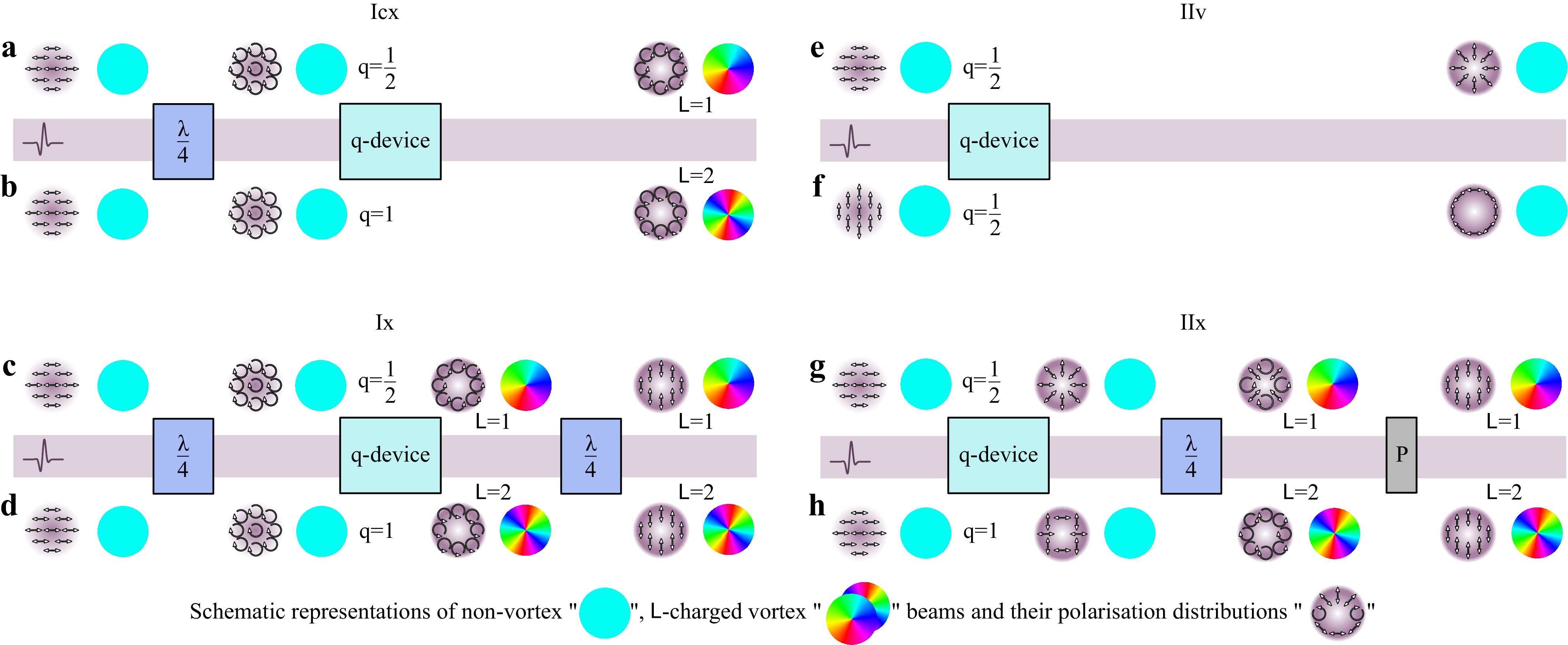
Fig. 2 Two main scheme types (I and II) for THz vector (v) and vortex (cx, x) beam shaping, respectively.
$ \mathsf{L} = \pm1 $ a, c, g and$ \mathsf{L} = \pm2 $ b, d, h charged beam with circular cx a, b, and linear x c, d, g, h polarisation, respectively; cylindrical v beams with radial e and azimuthal f polarisations respectively. The notations of polarisation elements are used:$ \lambda/4 $ is a quarter-wave plate; P denotes a linear polariser.Discrete q-plates are well established tools for vector and vortex beam shaping in the optical domain. Nevertheless, the most vital limitation of q-devices is the requirements for the incident beam52. In most cases, the design of the q-plates is done for the collimated beam with flat wavefront. In the non-paraxial case, the incoming beam wavefront has a complex angular spectrum, resulting in the inhomogeneities of the phase delay distribution. Moreover, such devices usually operate in the limited spectral band. In the second paper38 of this paired set, we discuss that these features in the spatial distribution of the phase delay can be tracked using THz PTDH.
To overcome the wave plate and q-device chromatic limitation to be applicable for broadband THz radiation, materials, and devices with dispersion properties less sensitive to the incident radiation frequency are required. This demand causes the task of developing of achromatic quarter- and half-wave plates design for a broad frequency range. Several approaches to the design of achromatic wave plates and devices have been proposed: multilayer stacks of birefringent material layers124−128, total internal reflection68, liquid crystals129, and metasurfaces74, 130−132 (Fig. 3). In subsequent section we will briefly overview all of them.
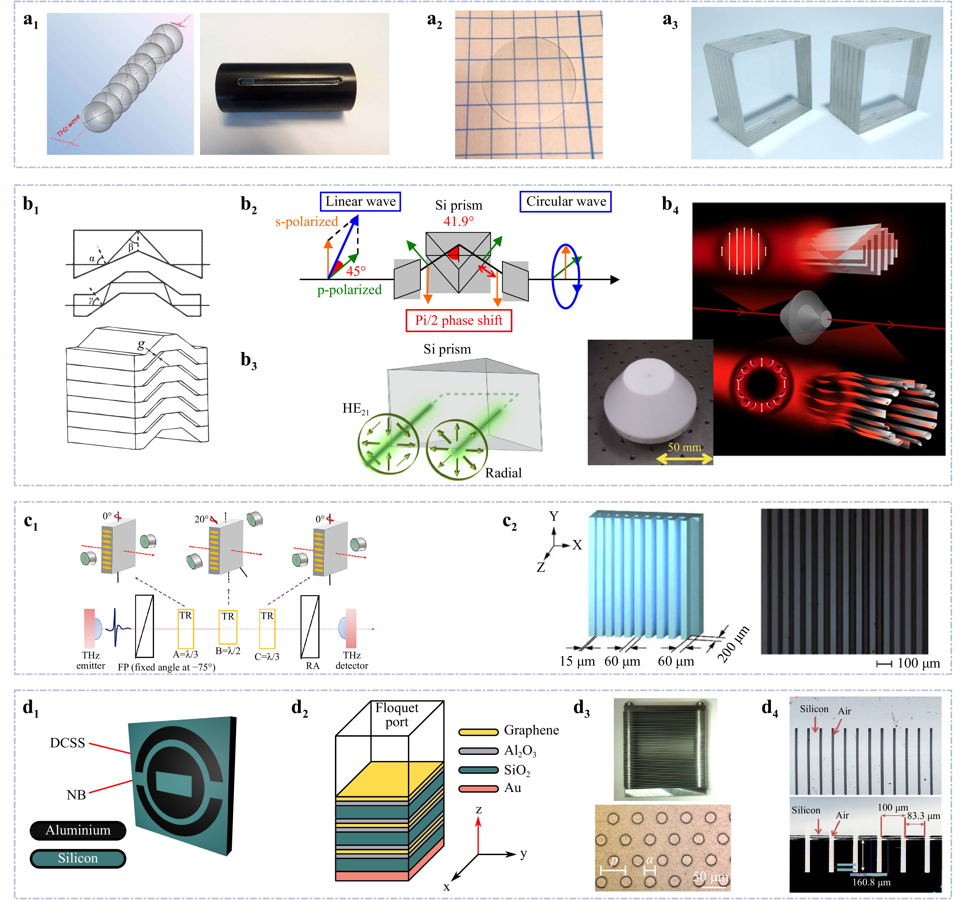
Fig. 3 Examples of THz achromatic polarising components: a multilayer birefringent media, b total internal reflection devices, c liquid crystals, d multilayer metasurfaces. a1 The achromatic QWP made from crystalline quartz plates125. a2 The birefringent sapphire disc128. a3 The achromatic HWPs made from crystalline quartz plates (our work). b1 The three-, four-reflection type prisms and the multistacked prism-type wave plate68. b2 The scheme for the linear-to-circularly polarised THz radiation conversion with the total reflection in the Si prism133. b3 The triangular Si prism as HWP112; b4 (main) the illustration of THz vectorial vortex control134 (CC BY 4.0) and b4 (inset) the polytetrafluoroethylene axially symmetric wave plate53. c1 The scheme of the LC-based achromatic wave plate with three magnetically tuned elements135. c2 The sub-wavelength dielectric gradient grating136. d1 The geometric phase building block74 and d2 the graphene-based unit cell75 for the metasurface vortex plate. d3 The parallel metal plate waveguides with a pillar array131. d4 The achromatic silicon-grating-based QWP132. Images adapted with following permissions: a1125 from Elsevier; a2128, b4 (inset)53 from Springer Link; b168, b2133, b3112, c1135, c2136, d3131, d4132 from The Optical Society.
-
Natural birefringent media, highly transparent within a broad THz spectral range, such as crystalline quartz and sapphire, are well suited for the manufacture of wave plates. However, bare substrates will introduce linear chromatic dispersion.
The method of achromatic wave plates engineering for a certain visible wavelength range has been known for over 50 years137. To even out phase retardation at all wavelengths of interest, a stack of birefringent plates is designing, where the achromaticity is achieved by tailoring plates’ thicknesses and orientations138. Similar procedure has been applied for the design of achromatic wave plates for the THz range, using both crystalline quartz and sapphire as birefringent media124−127.
Masson and Gallot were the first to present an achromatic quarter-wave plate, consisting of six layers and operating in the range from 0.25 to 1.75 THz to achieve a phase delay of
$ {\pi }/{2}\;\pm 3\% $ 124. The total thickness of the wave plate was 31.4 mm, corresponding to an amplitude transmission at 1 THz measured to be equal to 74%, most losses being introduced by the Fresnel reflection at the wave plate interfaces. The following study125 provided design of an achromatic quarter-wave plate with retardance stability of$ \pm 3{^\circ} $ around$ {\pi}/{2} $ in the frequency range of 1.3 – 1.8 THz. This wave plate was composed of nine layers of crystalline quartz (Fig. 3a1) and had a total thickness of 51.72 mm. It should be noted that the use of crystals with strong anisotropy, for example, sapphire$ \left( \text{A}{{\text{l}}_{\text{2}}}{{\text{O}}_{\text{3}}} \right) $ with a large birefringent contrast$ \left( {{n}_{o}} = \text{ }3.39,\,{{n}_{e}} = \text{ }3.07 \right) $ , allows thinner layers and, hence, results in thinner wave plates. Taking this fact into account, Wu et al.128 designed and fabricated a thinner achromatic quarter-wave plate based on stack birefringent sapphire discs (approximately 3 mm total thickness) with an overall phase error of a few percent in the 0.1 – 0.8 THz range (Fig. 3a2). The transmittance of this plate is between 60% and 40% in the range of 0.1 to 0.8 THz, and again most losses are present due to the Fresnel losses what is cause by the higher values of the sapphire refractive index. However, according to our simulation which is reported in the second paper38 from this paired set, these sapphire wave plates may be inefficient for vortex beams formation, since they do not yield the desired phase difference$ \Delta \varphi = \varphi_x - \varphi_y = \pi/{2} $ and a perfect circularity.Despite the high transparency of crystalline quartz for THz radiation, which is greater than that of many plastics, it multilayer slab can significantly (at times) attenuate THz radiation. Therefore, alternative possibilities for creating achromatic wave plates are also being explored. Tangible progress here was provided by the work of C.-J. Yang et al.139, in which it was shown that (110) and (001) cuts of DyScO3 crystals have a fairly wide frequency range of minimal dichroism, which makes it possible to use 50 and 370
$ \mu $ m-thick crystals as QWP in the frequency ranges 0.5 – 0.7 and 0.5 – 0.61 THz, respectively, for each of the cuts.Multilayer achromatic wave plates (Fig. 3a3) can be employed to manufacture achromatic q-plates for the formation of broadband THz vortex fields. Stacks of several q-plates140 will allow introduction of an arbitrary shape of the geometric phase into the passing THz beam and reproduce a large set of OAM values and their superposition141.
The first and unique demonstration of wave plate vortex beam shapers in the THz range was published by Minasyan et al.67, where using a single-layer eight-sector quartz q-plate with a charge of
$ q = 0.5 $ installed in scheme accordingly to Fig. 2c, they demonstrated the possibility of obtaining a vortex vector beam at a frequency of 1 THz. As the wave plates they used were not achromatic, the presence of the vortex was shown only at a single frequency, a narrow bandpass filter was used in the experimental demonstration. While the perspectives of using achromatic wave plates in the same setup and achieving broadband THz vortex beams were discussed in the aforementioned paper, experimentally such generation has not been demonstrated to date. As was shown by Gecevicius et al.142, for the broadband beam passing through the narrowband chromatic q-plate introducing half-wave retardation at a specific frequency$ {{\nu}_{0}} $ only, a very limited part of circularly polarised radiation outside a design frequency$ {\nu \ne \nu_0} $ changes its helicity and transforms into a vortex beam, while most radiation is converted into some unstructured vector field.To clean all non-vortex beam components, polarisation filtering142 should be performed. Provided that the input THz field has circular polarisation uniform over the entire spectrum, spectral density after such conversion is modulated by the following frequency dependence:
$ \Big(1- \exp\big(i\pi({\nu}/{\nu_0})\big)\Big) $ . Spectral efficiency of such conversion by monochromatic q-plate, optimized for the frequency of$ \nu_0 = 0.75 $ THz, we calculated, as shown on Fig. 4a1. The narrow bandwidth of the output vortex suggests that an achromatic q-plate should be employed for the formation of a THz vector vortex beam with higher purity and better conversion efficiency. We have designed such a q-plate. Its concept and the transformation of the structure of the THz field after its passage are discussed in detail in the second paper38 from this paired set.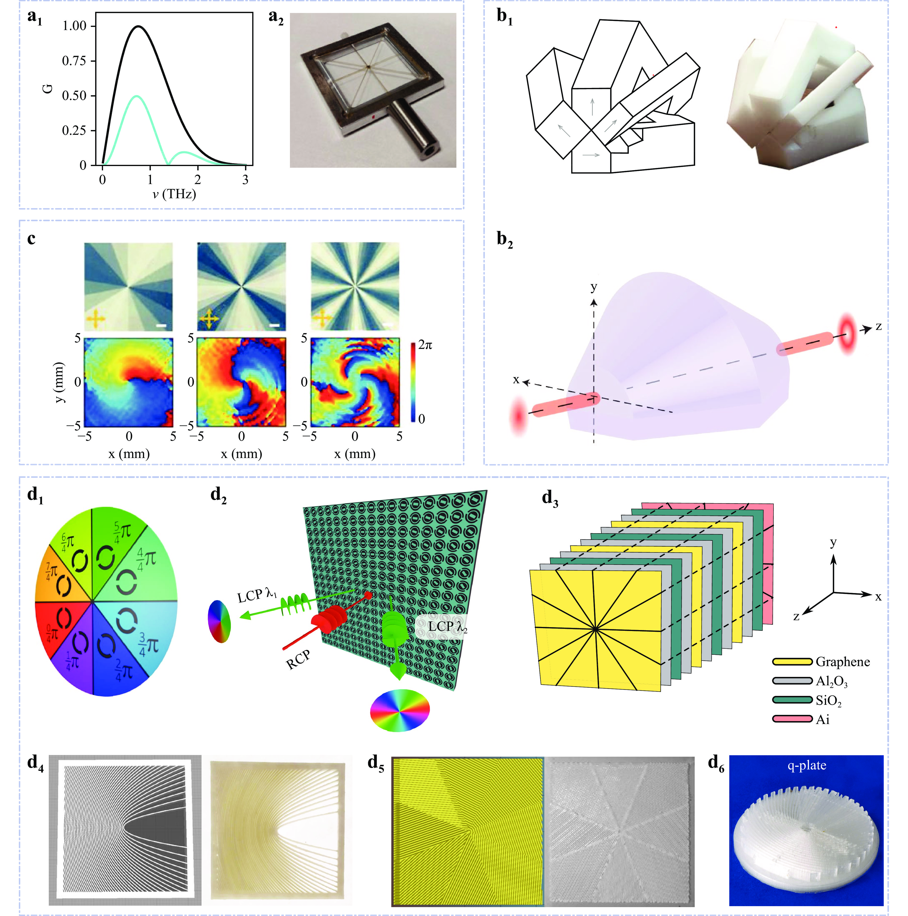
Fig. 4 Examples of geometric phase devices for THz frequency range based on: a achromatic birefringent wave plates, b total internal reflection, c liquid crystals and d metasurfaces. a1 The black and cyan curves show the original and modified after passing through the chromatic q-plate the modulus of the temporal spectrum (as described in Section “Achromatic birefringent wave plates”67, 70, 71) and a2 the image of sectorial chromatic q-plate (the photo was courtesy provided by Emmanuel Abraham). b1 Schematic representation of segmented achromatic q-device for broad THz range and its image69, b2 the achromatic non-axially-symmetric continuous body q-device69 (adapted, CC BY 4.0). c Photos and measured phase distribution at
$ \nu = 1 $ THz from a liquid crystal polymer q-plates with charges L = 1, 2, and 471 (adapted with permissions from John Wiley and Sons). d1 The phase distribution in the THz beam reflected from the corresponding sectors of metasurface145. d2 Dual-band reflective74 and d3 multilayer transparent75 metasurface vortex plates. d4 The continuous, d5 polylactide146 and d6 cyclic olefin copolymer147 (adapted with permissions from The Optical Society) sectorial 3d-printed sub-wavelength q-plates with$ q = {1}/{2} $ . -
One of the most promising candidates for achromatic devices in the broad frequency range are devices based on total internal reflection (TIR), as there are plenty of materials with flat refractive index dispersion in the THz range133. Among the achromatic TIR components developed to date for the THz range, one can find Fresnel prisms33, 133, 112 (Fig. 3b4) and non-axially symmetric wave plates introducing angular variation of the beam phase shift69 (Fig. 4b1, b2). We note that polarisation tailoring by TIR inside the cone143 can also be used for such purpose, though it has not been realised in the THz range yet.
Arbitrary TIR local change polarisation state in broadband THz beam can be performed by several complete internal reflections within a prism when, for instance, linearly polarised THz radiation is converted to circularly polarised radiation (Fig. 3b2). Importantly, a total reflection phase-shift is independent of the wavelength due to the flat dispersion of prism material (Si) in the THz frequency range. Increasing the incidence angle up to
$ {{45}^{\circ }} $ gives approximately$ \pi $ of phase shift between orthogonal polarisation components, thus a half-wave retardation has been performed (see Fig. 3b3). Implementation of this approach for the visible range was experimentally demonstrated in TIR device by Wakayama et al. in 2012144 and then reproduced with metasurfaces by F. Bouchard et al. in 201463. The same year, Kawada et al.68 designed and manufactured TIR based element for the broadband THz wavelength range, which included half- and quarter-wave plates (Fig. 3b1). A stack of cyclo-olefin polymer prismatic elements of three- and four-reflection type prisms were assembled to wave plates, which demonstrate achromatism over a wide region of the THz spectrum from 0.1 to 2.5 THz. Later, this group proposed a cylindrical symmetric TIR element in the form of two glued hollow truncated axicons134, 53 (Fig. 3b4), which provides rotation of the polarisation due to Fresnel reflection, causing a change in the phase of the vortex due to the SAM-OAM coupling. It modulates the polarisation states of the beam depending on the azimuthal angle, which leads to the transformation of a uniformly polarised Gaussian beam into a vortex one with a uniform state of polarisation along its cross-section.Later the same group of researchers69 proposed two variants of non-axially-symmetric half-wave plate, equivalent in their principle of operation to a q-plate with
$ q = 0.5 $ . The first of the configurations designed and manufactured for the THz range, consists of four segments oriented at azimuthal angles of$ \psi = 0,\; {\pi}/{4} $ ,$ {\pi }/{2} $ and$ {3\pi }/{4} $ (Fig. 4b1). Each segment of this device is formed by a pair of Fresnel rhombuses providing a certain number of TIR from their faces. In contrast to the work of Kawada et al.68, relative shift between orthogonal polarisations, giving a phase delay equal to$ \pi $ , was provided after four TIRs. Since the paper also considers the prospects of using non-axially-symmetric elements for shorter wavelength spectral ranges, where higher precision requirements for processing and assembly complexity make it difficult to implement the proposed solution, non-axially-symmetric half–wave plate realised in a continuous body (Fig. 4b2) was proposed. Such an element is an assembly of two components obtained by rotating the Fresnel rhombus at an angle of 90° along the beam propagation axis. -
Liquid crystals (LC) are another promising class of anisotropic material suitable for manipulating the THz wavefront by achieving a geometric phase shaping and thus suitable for application in vortex and vector beam modulators. They are attractive due to the controllability of the director distribution (e.g. fast optical axis) and sensitivity to the external electric148−152, and electromagnetic153 fields, as well as temperature52, 154), allowing to consider them as one of the promising approaches for OAM dynamic control, needed, for example, in wireless and optical telecommunications52. To date, various LC based THz polarisation devices have been proposed: phase-shifters148, 150, 155, 156, wave plates152, 157, 135, gratings158, 159, q-plates70 and other beam shaping plates160, 71.
Among commonly used LC materials, the most inte-resting for the THz beam shaping applications are nematic LC E7 (by Merck) with a birefringence of 0.130 – 0.148 in the frequency range between 0.2 THz to 1.2 THz150, 135, 136; MDA-00-3461 (by Merck) with birefringence is about 0.2 in the range between 0.3 – 1.4 THz129 and LC NJU-LDn-4 with an average birefringence of 0.306 in the range between 0.5 to 2.5 THz152, 159, 157, 70, 160. High birefringence allows for quite subtle polarisation control. This feature is important because it is quite difficult to perform homogeneous or desired prealignment in thick cells and high operating voltage. Using remarkably narrow LC cell gap of 125
$ \mu $ m thickness with nematic LC NJU-LDn-4 in the 0.5 – 2.5 THz band, Wang et al. developed electrically controlled both transmissive152 and reflective157 phase retarders. Proposed structure with sub-wavelength metal grating electrodes allowed a controlled phase delay in two operational modes: tuneable quarter-wave plate, covering the range between 1.1 – 2.5 THz, and half-wave plate for 2.2 – 2.5 THz range. In addition to bias control, phase delay after the reflecting LC cell can be adjusted by the beam angle of incidence, thereby realising a more flexible control of the output polarisation state157. Each of the materials has a response time of the order of several milliseconds, making it possible to create fast controlled LC converters with a given phase delay on its basis. For vectorial THz broadband beam shaping, cells providing$ \pi/2 $ or$ \pi $ phase retardation in a broad frequency range are required.Regarding the achromaticity requirement, we note that all of the above devices provide required phase delay only at a certain frequency. For the phase and polarisation conversion purposes of broadband THz beams, it is necessary to tune the LC cells continuously within the operating range. Thus, the main disadvantage of such devices is the dispersion of phase retardation. At the same time, there are practically no works aimed at achieving an achromatic phase shift in the THz spectral range at the moment, with very few exceptions129, 135, 136.
On the basis of an approach similar to that used for achromatic crystalline birefringent wave plates, a broader tuneable range can be achieved by stacking LC cells, thus cancelling dispersion and improving conversion efficiency over the entire THz range. In two recent works129, 135 retarders consisting of three discrete LC cells with different thicknesses demonstrated achromatic tuneable THz quarter-wave plate in a relatively wide band from 0.20 to 0.80 THz129 and from 0.20 to 0.70 THz135. The remarkable advantage proposed by Hsieh et al. retarder135 is in applying magnetic fields to tune LC without the use of transparent electrodes (Fig: 3c1), usually not too transparent for THz radiation. The overall loss of the proposed retarder is about 8 dB. However, other researchers note that devices controlled by a magnetic field are space-consuming, expensive, and high energy demanding152. Thus, it seems quite unfeasible that LC achromatic devices with spatially inhomogeneous polarising properties will be implemented in the near future. In addition to the achromaticity problem, the resulting cells demonstrate a complex dependence of the orthogonal polarisation components transmittance on the frequency, leading to an uneven radial distribution of the output beam at individual spectral components. Yang et al.150 compensated this disadvantage by using a nanowhiskers-structured substrate obtained from obliquely evaporated indium titanium oxide (ITO) by electron beam glancing angle deposition, which limits the electrically tuneable LC cell. This allowed greater transparency (77.8% and 75.4%) in the range of 0.2 to 1.2 THz. However, 517
$ \mu $ m thick cell provided a phase shift of$ \pi/2 $ for frequencies of 1.05 THz and above only. Furthermore, the combination of subwavelength gratings with variable spacing between grooves (Fig. 3c2) filled with mixture of polymer solvent epoxy resin and E7 LC allowed expanding the cell working range and equalising the transmittance of the two orthogonal components to 50%136. Phase shift of the proposed tuneable 500$ \mu $ m thick THz wave plate cell can vary from$ \pi $ to 0 rad near 0.8 THz, when the bias is increased from 0 to 80 V, thus realising both half-wave and quarter-wave plate properties. However, the authors succeeded in experimentally demonstrating the transformation of linear polarisation into elliptical polarisation at a given frequency only. It is also worth noting that in this work, the authors experimentally found that it is possible to introduce an achromatic phase delay$ \Delta \varphi = \pi \pm 20\% $ in the range of 0.55 to 1.05 THz with a Si grating whose anisotropy property originates from the gradients in the fill rate of Si between the gratings.Summarizing the state-of-the-art of LC based broadband THz vortex shaping, it should be noted that due to the technology immaturity for providing achromatic anisotropy, it is still problematic to form wave packets containing a BUTCH beam. However, taking into account the possibility of magnitude and introduced phase shift dynamic adjustment, it is possible to consistently form a vortex wave front at various spectral components over a wide THz spectrum.
LC-formed vortex structures were characterised by a holographic imaging system70, which is very similar by design to our detection module for THz PTDH manufactured on the basis of 3D-models with open-source codes161, 162. Despite the fact that LC cells were irradiated by broadband THz radiation, vortex phase distributions are demonstrated for a separate spectral component of 1 THz (or 1.2 THz) only. In the case of LC q-plate, with a 250
$ \mu $ m cell gap needed to obtain$ \pi/2 $ phase retardation at 1.0 THz (Fig. 4c), the recorded conversion efficiency reaches 50%. Due to the phase delay dispersion, the proposed LC elements could work effectively without full photopatterned realignment at a single frequency only, which puts them on a par with birefringent q-devices67. Another particular solution for shaping the THz vortex beam with LC cells was proposed by Shen et al.160. Digital micro-mirror device was adopted for dynamic micro-lithography to control the azimuthal angle inhomogeneity of LC directors to obtain the Bessel-like beam phase diagram with axial singularity. A cell gap was established at 400$ \mu $ m to meet maximum performance at 1.2 THz with half-wave retardation, when the output field exhibits characteristics of both vortex and Bessel beams. The works published to date on this topic use the scheme shown in Fig. 2c, d where micro-lithography photopatterned LC cells70, 71 are used as q-plates. The other solution for vortex beam formation with LC cell is the use of polarisation controllable geometric phase forked grating159. Further development towards achromatic tuneable LC based retardation devices will involve combination of LCs and metasurfaces163. -
Extremely elevated interest towards metasurfaces research in the recent years can be deducted from the number of review papers published in this topic over the past 5 years65, 164−174. Among the listed reviews, some are specifically focussed onto THz metasurfaces164, 165, 169, 172, while others are devoted exclusively to the IR range173. Such interest is driven by the great opportunities offered by the metasurfaces: extreme tunability through variation of their material and geometry, and possibility to fabricate dynamically controlled metasurfaces, extremely required for the development of compact, integrated photonic and optoelectronic devices.
Metasurfaces can be utilized in almost any optical component – either for enhancing its properties, or reducing the fabrication cost, size, and the amount of the material used. Based on the physical principle, metasurfaces can be divided into two main categories3, 172: the first category includes metasurfaces comprised of resonant subwavelength antennas which predominantly interact with linearly polarised radiation, while metasurfaces of the second category operate with circularly polarised radiation and based on geometric phase principle. The presence of resonance imposes an additional limitation on the frequency response of the first type metasurfaces. By contrast, the second type metasurfaces operate under the spin-orbit conversion principle, as discussed earlier, and such mechanism is well suited to provide achromatic properties65. In terms of vector and vortex beam shaping tasks, THz beam shaping metasurfaces can be divided into three classes: q-plate type devices, isotropic phase shifter175, 75, and radial polarisers. Only the first of these relate to the formation of vortex beams with geometric phase stitching will be discussed here. While the latter two types relate to multiplexing technologies and are beyond the scope of this paper. However, one cannot ignore the existence of the prominent phase shifter: the broadband tuneable reflector of a graphene-based metamaterial75. A schematic drawing of the composite metasurface is shown in Fig. 4d3. It is divided into 12 sectors, each filled with the same multilayer units (Fig. 3d2). In order to adjust the three chemical potentials and the corresponding surface impedances of the graphene layers, an external DC voltage is applied between the graphene layer and the SiO2 layer in each sandwich structure. The insulating layer is Al2O3; the THz beam is reflected from the Au base. The advantage of the proposed vortex beam modulator is the wide operating range 1.8 – 2.8 THz and the dynamic switching between different modes with OAM
$\mathsf{L} = \pm{1},\pm{2},\pm{3} $ .Metasurface-based q-devices, similarly to natural birefringent material-based components, employ geometric phase conversion for vector and vortex beam shaping in the THz range. In work145 3-bit active Pancharatnam–Berry coding metasurfaces are developed to modulate the amplitude of reflected THz beams. The reflection phase distribution of the coding particles which is shown in Fig. 4d1. Each meta-atom has a specific local axis rotation by a certain angle within [0,
$ \pi $ ] range. Nevertheless, to date, numerous solutions72, 146, 147, 176−181, operating either in narrow frequency band or having flat enough birefringence to be applicable for wider spectral range devices, still introducing a frequency dependent phase shift though149. Among these plethora of solutions, easy-to-manufacture 3d-printed plates shine out (see Fig. 4d5, d6)177, 178, 146, 180, 147. The grating structure has a period of 0.4 – 0.7 mm and wall thickness of$ 0.22\pm 0.02 $ mm made of COC-filaments. In dependence of the grating height, a quarter- or half-wave retardance can be achieved. Some solutions, similarly to liquid crystals, can dynamically change their properties thus allowing for tuneable beam shaping devices181−183.Due to the large amount of research aimed at metasurface design, the state-of-the-art in achromatic meta-based wave plates and q-devices design is significantly more diverse and developed than all other previously mentioned approaches. In184 the design of a flat achromatic reflective quarter-wave retarder operating in the frequency range between 1.8 – 2.8 THz is proposed. The achromatic quarter-wave plate based on a stack of overlapped parallel metal plates with sub-wavelength holes is demonstrated in130. This waveguide with a controlled gap between the plates is an effective medium without significant losses, allowing for easy dispersion control of the entire birefringent structure via chemically etched array of through holes. Operating range of the proposed achromatic wave plate occupies about one octave (0.67 – 1.21 THz). Subsequently, to shift the achromatic operating range to higher frequencies (2.0 – 3.0 THz), the authors replaced the holes with periodic rough structures (pillars) of
$ 3.7\pm 0.5 $ $ \mu $ m height and diameter around 20$ \mu $ m131. The stack of plates that functions as an achromatic quarter-wave retarder (Fig. 3d3) with a 7% deviation from the ideal$ \pi/2 $ was experimentally demonstrated. In addition, other metallic multi-functional broadband metasurfaces were proposed185, 186, that can be employed as achromatic polarisation elements for the formation and dynamic modulation of THz optical vortices and vector beams, were proposed.In work187, the metamaterial design of two waveguide arrays is discussed. In the numerical experiment the phase difference of
$ \pi/2 $ was achieved in the range between 0.89 – 1.22 THz.All-dielectric subwavelength gratings offer better transmittance characteristics than metal plates188. In work189, two achromatic wave plate designs are proposed, with operating ranges of 0.67 – 1.35 THz, and 0.70 – 0.85 THz, respectively. Birefringence effect190 can also be used to design achromatic wave plates132. Three achromatic plate designs are proposed in the referenced work, operating in the ranges 0.7 ± 0.3 THz, 1.0 ± 0.45 THz and 5.0 ± 2.16 THz (Fig. 3d4).
Some broadband metasurface solutions proposed for the visible range are not yet adapted for THz wavelengths191, 192, though potentially can be. To make the picture complete, we would like to note the work by Lin et al.193, containing an overview of methods for the formation of broadband vortex beams in the SHF (microwave) radio wave range194, 195.
By locally tailoring the metasurface structure, Zhang et al.89 designed and fabricated polarisation-independent transmission-type spiral phase plate with 8, 16, and 32 sections. Proposed metasurface consists of multi-sized silicon pillars which perform formation of
$ \mathsf{L} = 1 $ ,$ \mathsf{L} = 2 $ , and$ \mathsf{L} = 4 $ optical vortices at 1.0 THz with efficiencies up to 75.2%. In the work by He et al.21, vortex beam shaping by a metasurface with V-shaped resonators at 0.75 THz is considered, but its operational spectral width is not discussed. Furthermore, vortex beam shaper for the THz wave range with spatially arranged aluminium building blocks of reflective metasurfaces is proposed by Li et al.196. By rotating a double-C-shaped slot (DCSS) and nano-bar (NB) resonators in the unit cell (Fig. 3d1), the geometrical phase shift is imprinted onto the incident circularly polarised wave and thus convert it into the wave with opposite helicity74. From the units, the metalens (Fig. 4d2) with a helicoidal phase delay is constructed. These reflective metasurface devices operate in 0.3 – 0.7 THz range and generate optical vortices with topological charges of$ \mathsf{L} = \pm1 $ and$ \mathsf{L} = \pm2 $ . The sign of the output charge depends on the incident circular polarisation handedness. Due to the reflective design, the conversion efficiency of the metasurface may reach 80% and 92% at 0.45 THz and 0.7 THz, respectively74By introducing vanadium dioxide (VO2)197, 198 into the metasurface, Wang et al.199 designed temperature tuneable metasurface for Pancharatnam-Berry phase modulation of circularly polarised THz waves as well as linearly polarised waves retardance. Proposed device operates at 0.62 – 1.3 THz band and forms vortex wavefront with the unit topological charge. Promising solutions for switchable metasurfaces by changing electrical parameters200 or chemical potential of graphene layer were proposed175, 75. From the tailoring approach point of view, such metasurfaces do not behave as PBOEs, as, for example, ones in89, but are employing scalar wavefront conversion method, as SPPs.
Comparison of the characteristics of the mentioned materials suitable for the manufacturing of the achromatic THz wave plates and other THz optical elements is presented in Table 2, while the Table 3 summarise the relevant information about beam converters, demonstrated to the date.
Ref. Material Thickness, mm Range, THz Retardance Tolerance Type Notes Multilayer wave plates 124 Quartz 31.4 0.25–1.75 π/2 3% A 6 layers 125 Quartz 51.72 1.3–1.8 π/2 ±3 deg. A 9 layers 126 Quartz — 1.0–5.0 π/2, π 10% A T 3 layers 127 Quartz — 1.11–1.87 π/2, π ±5 deg. A T 3 layers 128 Al2O3 2.453–3.419 0.2–2.0
0.1–0.8π/2 0.5% (simul.)
4.7% (exper.)A 6–8 layers Our work Quartz 17.66
22.960.4–1.4
0.4–1.4π/2,
π0.5% (simul.) A 7 layers 139 DyScO3 0.05
0.370.5–0.7
0.5–0.61π/2,
π/2±3% (phase)
±10% (ampl.)A 1 layer Total internal reflection wave plates 68 Si and plastic 122 0.1–2.5 π/2; π — A Transmissive Liquid crystal-based wave plates 150 E7 ~0.52 1.05–1.2 π/2 — T Transmissive 152 NJU-LDn-4/1 0.25 1.1–2.5
2.1–2.5π/2
π— T Transmissive 152 NJU-LDn-4/2 0.5 0.5–2.5
0.9–2.5π/2
π— T Transmissive 157 NJU-LDn-4 ~0.13 1.1–2.5
2.2–2.5π/2
π— T Reflective 70 NJU-LDn-4 0.25 >2.0 π — T Transmissive 129 MDA-00-3461/4 0.8–1.0 0.35–0.5 0.2–0.9 π/2 — A T 3 LC plates 135 E7 2.56–3.86 0.2–0.5
0.3–0.7
0.8–1.0π/2
π/2
π±9 deg. A T 3 LC plates in magnetic field 136 Si sweep grating
with E7 & epoxy0.5 + 0.5 0.375–1.1
0.8–1.1π/2,
π— T Transmissive Metasurface wave plates 136 Si grating with gradient period 0.015–0.06 0.55–1.05 π ~20% A Transmissive 184 Polyimide on Au 0.02–0.04 1.8–2.8 π/2 ±2 deg. A Reflective 130 Metal 0.06–0.1 0.67–1.21 π/2 5% A Transmissive 131 Metal 0.02–0.04 2.0–3.1 π/2 7% A Transmissive 185, 186 Metal on polyimide 0.066 1–1.4; 1.4–1.8 π/2 ±5 deg. A T Transmissive 2 +
3 layers187 Al on polymer 0.02–0.07 0.89–1.24 π/2 ±10 deg. A Transmissive 189 Al 0.02–0.2 0.7–0.85
0.67–1.35π/2, π ±5 deg. A T Transmissive 190 PP loaded TiO2 0.15–0.25 0.15–0.375 π/2 — A Transmissive 132 Si grating 0.14–0.15 0.47–0.8 π/2 ±3% A Transmissive 147 Olefin copolymer 0.41-0.66 0.23-0.4 π/2 ±10% A Transmissive 2 layers Table 2. Achromatic (A) and tuneable (T) THz wave plates
Ref. Material Thickness, mm Range, THz Type Retardance Beam type Notes Segmented birefringent beam converters 67 SiO2 single layer — 1.0 Ix, IIa π Vectorial, Vortex ${{\mathsf{L}}=\pm1}$ Chromatic 38 SiO2 multi layer — 0.1–1.4, 1.9–2.6 Icx, Ix π Vortex ${{\mathsf{L}}=\pm1}$ Achromatic Total internal reflection beam converters 134, 53 (C2F4)n — 0.1–1.6 IIv π/2
163 degVectorial Achromatic 69 (C2F4)n — 0.1–1.6 IIv π Vectorial, Vortex Achromatic Liquid crystal beam converters 159 NJU-LDn-4 0.25 1.0 Icx π/2 Vortex ${{\mathsf{L}}=\pm 1}$ Chromatic 70 NJU-LDn-4 0.25 1.0 Ix π/2 Vortex ${{\mathsf{L}}=\pm1}$ ${{\mathsf{L}}=\pm4}$ Tuneable 160 NJU-LDn-4 0.4 1.2–1.4 Icx π Bessel-Vortex ${{\mathsf{L}}=\pm 2}$ Broadband Metasurface beam converters 196 Al on polymide 0.05 0.3–0.45 Icx 0−2π Vortex ${{\mathsf{L}}=\pm 1}$ ${{\mathsf{L}}=\pm 2}$ Achromatic 74 Al on Si 0.06 0.45 and 0.7 Icx 0−2π Vortex ${{\mathsf{L}}=\pm 1}$ ${{\mathsf{L}}=\pm 2}$ Tuneable 75 Graphene on Al2O3/SiO2 0.02 1.8–2.8 – 0−2π Vortex ${{\mathsf{L}}=\pm 1}$ ${{\mathsf{L}}=\pm 2}$ ${{\mathsf{L}}=\pm 3}$ Tuneable (not a q-device) 197 Au on polyimide with VO2 0.03–0.05 0.62–1.3 Icx 0−2π Vectorial, Vortex ${{\mathsf{L}}=\pm 1}$ Achromatic Tuneable 145 Ge on polyimide 0.01–0.05 1.0–1.2 Icx 0−π Vortex ${{\mathsf{L}}=\pm 1}$ Tuneable 146 PLA 2.3 0.14–0.16 IIv π Vectorial Chromatic 147 Olefin copolymer 0.22–1.5 0.325 IIv π Vectorial Chromatic Table 3. THz beam converters
-
After looking carefully at the collection of all reviewed approaches to achromatic device design for the THz frequency range, and noticing a great number of solutions, put together for easier assessment and comparison, we can try drawing a whole picture of the state-of-the-art and perspectives in this area of research.
The first thing to notice, all the proposed approaches can be classified into either Type I or Type II shaping, without offering any novel solutions, and search for such new shaping schemes may be the next direction of research in this area.
Multilayer achromatic wave plates from birefringent materials, being historically the first proposed solution, still offer the best operational spectral range, and have significantly progressed, becoming thinner and easier in production, due to the designs including layers of the identical thickness. Further development of metasurface based materials with exceptional birefringence, may give this approach a new kickstart, due to the controllability and compactness of the resulting devices.
Total internal reflection devices are quite accessible, as they can be directly 3d-printed, allow for relatively simple implementation of smooth gradient introduction, and offer exceptional spectral bandwidth, however, are rather bulky and thus are hard to integrate into the setup. With further development of higher refractive index polymers for 3d-printing, they potentially will become very competitive approach to achromatic vector and vortex beam shaping in the THz frequency band.
Liquid crystal-based devices, expectedly, allow for extra fine tunability, and potentially could be used in a multilayer device, however, the losses, introduced by the liquid crystals are often a limiting factor for their use as effective beam shaping approach for the THz frequency range.
Metasurfaces, allowing for extreme engineering of their properties and being still optically thin, are the main candidates for the future broadband THz beam shapers. Active metasurfaces will allow on-line adjustment of the wavepltes to the needs of the beamshaper, and possibly even tune the output beam topological charge and/or polarisation. Combination of metasurfaces of a different kind with other approaches, such as multilayering and liquid crystals, can possibly become an ultimate solution for compact, efficient, and tuneable BUTCH beam shapers in the THz frequency range.
-
In this part of our paired set of papers, we reviewed materials, methods, and solutions for geometric phase and beam shaping and polarisation control in the THz frequency range. We have outlined the basic schemes for achromatic vortex and vector beam shaping and brought together the available approaches for the development of birefringent components. We classified, described, and characterised most existing different beam-shaping techniques and discussed the possibility of creating the new setups and schemes for these purposes. We also overviewed and compared materials and methods, with special focus on their broadband operation, to be applicable for pulsed THz beam shaping.
The effective way to expand the range of achromaticity that has already been implemented in three of the four types of geometric phase devices discussed in this review is the concept of multilayer composition. The use of a layered structure makes it possible to compose materials with the wide operating spectral range, in which the differences between the boundary frequencies can be as much as tenfold differential. However, adding more layers leads to the degradation of the integral transmittance and increases the cost of the product. Furthermore, other experimental factors, such as thickness neglect, the impact of the Fabry-Perot effect between the layers, or large wavelength differences at the limits of the designed spectral range), which are weakly expressed with the small number of layers, become appreciable.
Within the considered framework, layered crystalline wave plates are promising for the manufacture of high-efficiency retarders. The process of designing a multilayer achromatic structure for the case of using natural birefringent media is the most developed. The need to use precision polishing and assembly equipment, accompanied by proper control, acts as a factor that increases the cost of production.
Liquid crystals and metamaterials are the most perspective way components from the point of view of the possibility to achieve switchability for different THz ranges. Solutions were proposed for both reflection or transmission modes of operation,
$ 0-2\pi $ phase conversion, and high fidelity. To date, they are still limited in continuous THz range coverage and require reconfiguration or re-writing of the cells to maintain a specified phase delay at the desired working frequency. Considering the concept of multilayer elements for chromatism cancelation, we should expect the development of broadband LC and metamaterials toward multilayer structures, which is already outlined in some research today.Devices based on total internal reflection stand apart from the materials discussed, because a completely different physical principle is involved. A distinctive feature of plastic materials is their sub-THz transparency; combined with cheap 3D printing, it will allow one to create wave plates and elements based on them in a certain range of frequencies. Along with this, total internal reflection elements made of Si and plastic materials extend the operating range of retarders. Already existing work shows that this is a promising solution for vector field transformation. A fundamental limitation in the selection of materials for achromatic beam converters based on total internal reflection is also their limited transmission and absorption characteristics.
-
The Authors thank Dr. Yaroslav Grachev for the photo of achromatic quartz wave plates, shown in Fig. 3a3. Russian Science Foundation, Project No 19-72-10147. The work of A.G. is supported by EPSRC Grant No. EP/S018395/1


 DownLoad: