


-
Additive manufacturing, or three-dimensional (3D) printing, is poised to revolutionize manufacturing. The United Parcel Service (UPS) and the Consumer Technology Association (CTA) project that the industry is to exceed $21 billion in the early 2020s, thus continued progress in this space is critical to global economic competitiveness1. The transformation of 3D printing necessitates reliable control over the end product’s geometric complexity in addition to mechanical, chemical, and biological material properties. Despite the plethora of existing 3D printing technologies; e.g., fused deposition modeling (FDM)2, direct ink writing (DIW)3, inkjet4, two-photon polymerization (TPP)5, and stereolithography (SL)6-8), new and improved methods are continually presented to overcome the grand challenges of spatial resolution, fabrication throughput, and multi-material capability, aimed to uncover unprecedented functionalities. For example, SL techniques, a subset of additive manufacturing modalities that harness light to create 3D objects, accomplish intricate layer-by-layer or non-layered 3D fabrication that finds applications in a number of areas, including microfluidic devices9–11; miniature actuators12; biomedicine and biotechnology13; and optical devices14. The two main modalities of SL are distinguished by the patterning process: (i) laser scanning—wherein a focused laser beam is scanned in a point-by-point (one-dimensional (1D)) manner to crosslink a two-dimensional (2D) planar pattern15, and (ii) projection-based—whereby an image is illuminated to simultaneously solidify an entire 2D layer or surface6, 8, 16–18. Accordingly, projection-based SL affords higher throughputs than scanning-based SL due to its ability to its 2D crosslinking nature vs the 1D approach in the laser method. The projection-based digital light processing (DLP) microstereolithography process uses high-resolution planar ultraviolet (UV) 2D projections illuminated at the surface of a liquid photocrosslinkable polymer precursor17, 19–22. A computer-aid design (CAD) model is first discretized into a series of parallel digital masks, which are then fed to a digital light processing (DLP) projector that creates the pattern using a digital micromirror device (DMD) chip. Light-based 3D printing approaches allow for both high resolution (sub-micron17) and high-throughput (up to 100 liters per hour, currently the fastest among direct ink writing or commercial 3D-printing platforms23, 24), laying the groundwork toward industrial-scale fabrication24.
Light-based micromanufacturing techniques can be further augmented by capitalizing on the phenomena of light self-trapping and self-propagation. In brief, incident light in conjunction with the associated photochemical reaction causes the monomer photopolymer to undergo local photopolymerization, thereby producing a spatially localized increase in refractive index. As the light beam continues propagating through the medium, the refractive index change (henceforth termed ‘index change’) causes a self-focusing of light along its propagation path. This self-focusing gives rise to characteristic self-propagating polymer waveguides (SPPW), in which the light beam continues propagating divergence-free in its own waveguide25-28. Through the strategic self-trapping and self-focusing of light in a photosensitive medium—primarily photopolymers—SPPW prototyping can be used to produce fiber-like structures in the nano- and micro-scales at unprecedented throughputs29. For example, SPPW enables the fabrication of materials with cellular architectures, including textured surfaces and interwoven 3D microlattices, which can be used as functional coatings such as liquid-repellant surfaces and light-guiding architectures. Such 3D microlattices tune the mechanical properties and density of these materials and can influence a wide range of other properties, such as mechanical, thermal, photonic, and biological, for applications in thin films, coatings, printing, dentistry, optics, and electronics. Table 1 outlines the range of additive manufacturing platforms that have been used to enable SPPW fabrication.
Platforms to enable additive manufacturing of polymeric structures
via self-propagating polymer waveguide (SPPW) phenomenonPropagating laser through liquid media Laser stereolithography (SLA)-based 3D printing Digital light processing (DLP)-based 3D printing Masked laser photolithography Physically masked, areal light source Spatial resolution Micrometer-scale Micrometer-
scaleMicrometer-scale Nanometer-scale (sub-wavelength) Micro- to nanometer-scale; limited by physical mask Geometrical freedom 3D, but straight inclined lines only Virtually unrestricted Virtually unrestricted No re-entrant feature capability Vertical beams only Material space Wide range of photopolymers Wide range of photopolymers Wide range of photopolymers Specialized, patented materials only Wide range of photopolymers Relative Capital Cost $ $$ $$ $$$$$; requires cleanroom $ Table 1. Performance comparison among technologies relevant to the SPPW domain.
Photopolymerization is a complex light-activated chemical reaction in which multi-functional monomers are covalently crosslinked into a 3D solid network. This process is accompanied by a multiplicity of chemical and physical changes, affecting the properties of the printed material such as the Young’s elastic modulus, relaxation time, and glass transition temperature30, as well as the geometry of the 3D-printed structure, hence governing the practical process resolution. In this review, we describe the wide variety of material systems that have been developed and refined for fabricating SPPW materials, including index-changing photopolymers, photopolymer blends, and doped photopolymer systems. We will elucidate general principles of designing polymeric materials to enable SPPW, with a view to understanding how chemistry and photopolymerization kinetics can be leveraged to achieve control over the morphology and microstructure of the product. Furthermore, the emergence of the light-based fabrication paradigm has necessitated the development of complementary predictive simulation tools to capture the physical and chemical phenomena involved in the SPPW process, namely photopolymerization kinetics, oxygen inhibition, photobleaching, diffusion, thermomechanics, and beam propagation. A multitude of predictive numerical models have been developed, albeit with key limitations. One-dimensional exposure threshold models such as the Beer-Lambert law31—wherein light intensity decreases exponentially with depth—neglect important phenomena such as oxygen inhibition and diffusion of reactive species32. Other models oversimplify reaction kinetics, considering only the relative conversion of monomers and neglecting the evolution of other chemical species33. Existing models specialized for self-trapped beams in liquid media also neglect the complex photochemical reaction kinetics34, 35. These oversimplifications of the process ignore important intermediate steps and thereby hinder models from precisely predicting the shape and properties of fabricated parts, particularly in the high-resolution regime. Thus, there is great opportunity for a complete model that unites the latest progress in radial-mediated photopolymerization together with models capturing self-trapping and self-focusing, for propagating light beams in photopolymer media. Next, we describe the key principles for material design and selection to enable SPPW, and present recent progress in the development of chemophysical modeling. We also discuss important applications of SPPW, including lightweight structures, energy absorption, heat exchanger, and biomimetic microstructures. Finally, we offer our perspective on outstanding challenges.
-
Self-focusing and self-trapping of light beams during photopolymerization are two processes necessary for self-propagating polymer waveguide (SPPW) fabrication. Self-focusing is initiated when an incident Gaussian light beam induces a refractive index change in the medium through which it travels. Initially, before the onset of polymerization, the incident beam can diffract freely through the liquid monomer. Over time, the exposed regions will undergo photopolymerization and solidify, which locally increases the index of refraction. The changes in refractive index contribute to the formation of a quasilens at the tip of this waveguide that focuses the light (i.e., self-focusing)36. These changes overcome the natural diffraction of the beam, causing the beam to taper and become trapped along the propagation axis. In other words, this self-focusing phenomenon counteracts the natural tendency of light to diverge along its propagation path. Consequently, the light beam continues propagating divergence-free, within its own self-induced waveguide26. The resultant material and the associated phenomenon are termed a self-propagating polymer waveguide (SPPW). A beam with a diameter D and wavelength λ is expected to diffract in a liquid with an angular divergence of θ ≈ 1.22λ/n0D, where n0 is the zeroth-order refractive index (refractive index at saturation). However, if the dielectric constant within the beam is sufficiently high and the critical angle for total internal reflection at the beam’s boundary is greater than θ, then spreading by diffraction will not occur and the beam is trapped in a line. For
$\theta \ll 1 $ , the following approximation is used:$$ P=\frac{\pi {D}^{2}}{4}\frac{{n}_{o}{E}^{2}c}{8\pi }\geqslant{\left(1.22\lambda \right)}^{2}\frac{c}{{64n}_{2}}\text{} $$ (1) where P is the total beam power, E is the field strength, c is the speed of light, and n2 represents the second-order nonlinear refractive index associated with high-frequency Kerr effects involving molecular orientation of liquids26. It is instructive to note that this nonlinear response in Eq. 1 implies that light cannot be focused to a point but is rather focused in a line with a diameter that depends on power. In contrast, the index response of a photopolymer is not electronic in nature but is rather due to a polymerization reaction, whereby the index change at a specific point of the incident optical field is delocalized.
This self-trapping phenomenon has been observed in a range of photosensitive materials, including photopolymers and photosensitive glass37,38. Frisken provided one of the earliest reports of SPPW systems, using a commercial epoxy to fabricate low-loss waveguides39. The epoxy contained acrylic acid and hydroxypropyl methacrylate and exhibited self-focusing once illuminated at a wavelength of 532 nm. Kewitsch and Yariv also provided early reports of SPPW, experimentally demonstrating self-focusing and self-trapping in a liquid diacrylate photopolymer26. They fabricated 3 mm-long waveguides with individual elements with diameters of 10 μm and reported that the cross-sectional area of the waveguide would have doubled in the absence of self-trapping26.
Seminal work by Shoji and Kawata demonstrated that two separate waveguides can merge into a single fiber under the appropriate optical conditions27. In addition to photopolymers, Brocklesby et al. provided some of the earliest experimental demonstrations of self-written waveguides in doped Bi4Ge3O12, a photosensitive glass40. Monro et al. also demonstrated self-focusing and self-trapping in a germanosilicate glass and modeled the evolution of channel formation37.
More recent work has demonstrated that SPPW formation can occur beyond the UV range. Soppera et al. demonstrated micro-lens fabrication via SPPW using near-infrared (IR) light emerging from an optical fiber. These waveguides were fabricated using trifunctional pentaerythritol triacrylate, a co-initiator, and a dye sensitizer that absorbed light in the excitation range of 750-900 nm. Incorporation of dyes and other additives provides an additional method of tailoring the waveguide properties to specific applications, which we discuss in forthcoming sections. Furthermore, SPPWs have been developed using multi-monomer blends41-43 and even polymer-nanoparticle solutions44, 45. In earlier studies using multi-monomer blends, waveguides were produced by sequentially or selectively curing monomers to form a core-cladding morphology that allows for sufficient light self-trapping and waveguide formation35, 42, 46, 47. It was later demonstrated that a similar binary morphology can be achieved without sequential curing. In this case, the monomers were chosen or modified such that they did not crosslink and the system lends itself to a process known as photopolymerization induced phase separation (PIPS).
In all of these materials, the self-focusing induced by the index change competes with the natural diffraction of the beam, ultimately giving rise to the characteristic waveguide structures. Photopolymers have shown particular promise in waveguide fabrication owing to their stability, rapid response time, and tunability. In photopolymers, the predominant mechanism that contributes to index change is densification/network shrinkage during polymerization16, 48. Since these changes are irreversible, the index change produced is preserved upon polymerization and gives rise to stable waveguides. Secondly, photopolymers exhibit rapid response times and are capable of producing index changes of ~0.04 in several seconds25. In contrast, waveguides can take several hours to form in photosensitive glasses37. Finally, photopolymers are highly tunable. Waveguide formation is highly dependent on the physicochemical and photonic parameters used49, which can be tuned to fabricate structures with diverse chemistries and properties. Collectively, the self-focusing of light in photopolymers during photolithography (used interchangeably with light-based additive manufacturing methods hereafter) allows for the fabrication of structures with micrometer-scale resolution by trapping light within a spatially confined region.
We next present different approaches for designing index-changing photopolymers for self-propagating waveguides. We consider these strategies at various length scales, starting at the molecular level with monomer chemistry. First, we note different approaches for tuning SPPW formation through rational monomer design/selection to augment index change. Then, we discuss different considerations for tuning waveguide formation by adjusting the kinetics of photopolymerization. Finally, we consider how kinetics can also be leveraged to achieve spatial control over the morphology and microstructure of the materials fabricated. At each level of analysis, we elucidate how fundamental principles of polymer chemistry can be used to achieve self-focusing during photolithography.
-
Although polymer network shrinkage is the predominant mechanism contributing to index change, it is possible to engineer additional index-changing components into the photopolymer to augment the self-focusing effect. The Lorentz-Lorenz equation (Eq. 2) describes the relationship between the refractive index
$ {n}_{D} $ , density$ \rho $ , molecular weight$ M $ , and the molar refractivity$ R $ of the material50;$ R $ captures the intrinsic refractive contributions of each functional group in the molecule and is directly proportional to the molecule’s polarizability51.$$ R=\frac{{{n}_{D}}^{2}-1}{{{n}_{D}}^{2}+2}\frac{M}{\rho } $$ (2) Equation 2 shows that we can achieve refractive index modulation (
$ \Delta {n}_{D} $ ) using materials that exhibit an increase in$ R $ and/or$ \rho $ during photopolymerization. The increase in$ \rho $ occurs readily in practice because the polymeric materials used for 3D printing, especially in acrylate-based systems that typically densify during polymerization in contrast to thiol-based step-growth photopolymerization. This densification arises as covalent crosslinking during photopolymerization draws the newly formed chains closer together48. The increase in$ R $ is more challenging to achieve, because the polarizability and therefore molar refractivity of the monomer generally decreases during polymerization52. This phenomenon arises from the conversion of carbon-carbon double bonds (higher$ R $ ) to carbon-carbon single bonds (lower$ R $ ) as the reaction proceeds to completion53. Therefore, the effects of network densification and polarizability act in mutually opposing ways: the former serves to increase the refractive index of the photopolymer, and the latter serves to decrease it. To promote self-focusing, our goal is to maximize the contribution of network shrinkage and counteract the contribution of polarizability changes. Other factors such as the wavelength of light, temperature, and presence of dopants can also affect the refractive index of materials.Researchers may benefit by adopting the following strategies to control the degree of change in the local refractive index—and thereby the structural shape—of the photopolymerizing region, to design materials that capitalize on optical self-focusing and self-trapping phenomena. In following sections, we will describe the following strategies:
(1) Utilize chain-growth radical-mediated photopolymerization that undergoes densification—a predominant mechanism of index change—instead of the step-growth thiol-based reaction
(2) Utilize lower-molecular weight monomers for higher shrinkage and index change
(3) Include photoactive phenyl-containing dopants
(4) Chemically conjugate/functionalize the monomer chains with pendant groups that induce index modulation
(5) Integrate photoacid generators in the photopolymer precursor
(6) Target a rate of polymerization within a window that is most conducive to self-focusing
(7) Design photopolymers attuned to thermal expansion and oxygen quenching-induced index change
(8) Use multi-monomer systems with varying refractive indices
(9) Employ phase-separating, immiscible photoreactive polymer blends
(10) Exploit photomasks to impact the morphology of crosslinked photopolymers.
-
The extent to which photopolymers densify depends on the structure of the monomer and the presence of diluents in the photopolymer. Aloui et al. compared the extent of volume shrinkage between different bifunctional ether acrylate photopolymers52. Photopolymers with higher molecular weight were found to exhibit less volumetric shrinkage and reduced index change upon polymerization (Fig. 1a). In addition, volume shrinkage was higher with aliphatic molecules compared to bulkier aromatic monomers (Fig. 1b). Furthermore, addition of the diluent poly(propylene glycol) diacrylate (PPGDA) increased the index augmentation achieved during polymerization (Fig. 1c). For example,
$ \Delta {n}_{D} $ of bisphenol A epoxy diacrylate in the absence of diluent was 0.0204, whereas$ \Delta {n}_{D} $ in the presence of TPGDA diluent was 0.0219. The effect of the diluent can be explained as follows. Firstly, the diluent lowers the initial refractive index of the pre-polymerized liquid precursor by increasing the effective intermolecular spacing. Secondly, such diluents lower the glass transition temperature Tg of the sample, which enhances the polymerization conversion and ultimately increases the amount of network shrinkage attainable. Therefore, Aloui et al. hypothesized that diluents enhance index change via two mutually cooperative mechanisms: reducing the initial density of the pre-polymerized precursor, and increasing the change in density (i.e., greater shrinkage) after polymerization52. Other diluents, such as ethylene glycol vinyl ether (EGVE) diluent, have also been deployed for fabricating polyurethane diacrylate waveguides54. Finally, the number of functional groups also plays an important role in determining network shrinkage. Zhang et al. studied self-trapping in organosiloxanes with varying concentrations of methacrylate groups in the monomer55. They found that monomers with more methacrylate groups resulted in increased index modulation and increased self-trapping efficiency.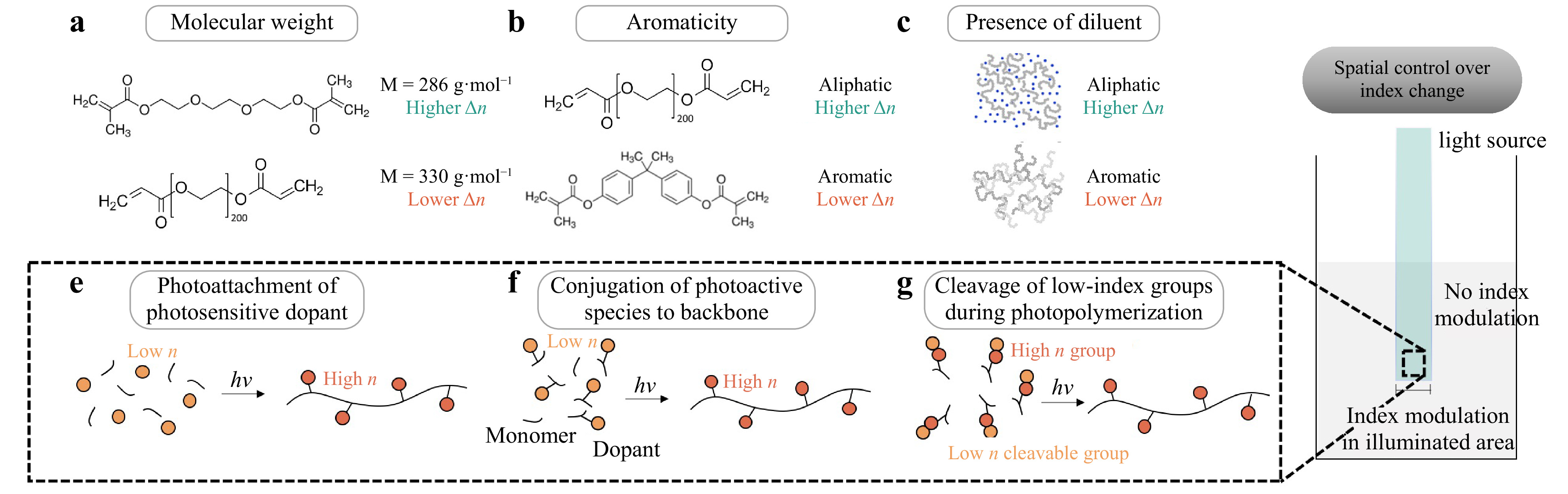
Fig. 1 Materials approaches for achieving index modulation for SPPW. Index modulation is increased by using a lower molecular weight monomers52, b aliphatic monomers52 and c an inert diluent52. d Spatial control over index change can be achieved by confining photopolymerization to the irradiated region. This can be achieved by e a photoattachment reaction of a photosensitive dopant to the monomer during polymerization64, f a photoactive molecule that is directly conjugated to the monomer51, or g a photoactivated cleavage reaction of low-index groups during polymerization63.
A major barrier to achieving
$ \Delta n $ is that vinyl monomers exhibit a decrease in polarizability during polymerization. One approach to counteract this effect is to incorporate a photoactive species that exhibits a polarizability increase upon irradiation. Tolstik et al. reported on the use of a photoactive dopant, phenanthrenequinone (PQ), for the fabrication of poly(methyl methacrylate) (PMMA) waveguides56, 57. Before polymerization, the monomer (methyl methacrylate) solution is doped with PQ molecules. During polymerization, UV light induces the irradiated PQ molecules to undergo a photoattachment reaction to the growing polymer chains (Fig. 1e). UV-visible light (VIS) spectroscopy data indicate that the molecular structure of PQ becomes less conjugated during photoattachment, giving rise to an increase in refractive index within the irradiated region58. Consequently, the irradiated regions undergoing photopolymerization experience an index increase from PQ photoattachment, whereas the non-irradiated regions exhibited no such index augmentation (Fig. 1d). Since the PQ dye is only a minor fraction of the material composition (<0.7 wt%), the structure of the overall polymer matrix is unaffected by the presence of the dopant59. Tolstik et al. used the PQ-doped system to fabricate waveguides using light self-trapping, with higher concentrations of PQ dopant producing greater index modulation56, 57. They found that index changes of around 10−4 with this photoattachment mechanism, which is lower than those achieved through network shrinkage. However, even these changes were sufficient for waveguide formation, suggesting that index changes on the order of 10−4 are sufficient for SPPW formation.Many photopolymer systems have been developed using the inclusion of photoactive dopants. Becker et al. fabricated optical waveguides using polystyrene doped with p-nitroaniline derivatives60. They hypothesized that the dispersion of the phenyl-containing dopants increased the electron density of the polymer matrix, which enhanced the index modulation. In a similar vein, Kudo et al. reported large refractive index changes before/after the irradiation of PMMA containing 2-phenyl-2,5-norbornadiene51. UV-Vis spectroscopy verified that the 2-phenyl-2,5-norbornadiene moieties were photosensitive and underwent photochemical isomerization upon irradiation, which mediated the index augmentation. Index changes were on the order of 0.05 to 0.1 with varying chemistries, which suggests these photoactive dopants hold promise in SPPW fabrication.
In addition to photoactive species added to the reaction mixture, the photoactive groups can be directly conjugated to the polymer backbone (Fig. 1f). PMMA with pendant anthracene groups also produced index modulation, and this system was used to fabricate waveguides61. The anthracene moieties were also found to be photosensitive, undergoing an analogous photoisomerization reaction upon irradiation. Morim et al. synthesized a poly(acrylamide-co-acrylic acid) (p[AAm-co-Aac]) hydrogel containing covalently attached SP chromophores62. Upon irradiation with visible light, the chromophore undergoes a photoisomerization reaction from an open-ring to a closed-ring form. Not only does the photoisomerization induce a local increase in refractive index, but it also increases the hydrophobicity of the hydrogel, triggering the expulsion of water and local network shrinkage of the hydrogel62.
Another strategy to locally increase the refractive index of the polymerizing region is to induce a structural change in the polymer itself. Kleine et al. developed an index-changing polymer system consisting of t-BOC-protected poly(4-hydroxystyrene), which was doped with photoacid generators (PAGs) in the reaction mixture63,64. During photolithography, UV irradiation causes the PAGs to undergo a photocatalytic deprotection reaction that replaces hydroxyl groups in the t-BOC sidechain with thiol groups. Since thiol moieties have higher intrinsic refractivity than hydroxy groups, this deprotection reaction increased the overall refractive index of the material (by an order of 10−2), which was subsequently used to fabricate waveguides. This example elucidates a novel approach for index modulation by directly modifying the structure of the repeat unit, swapping out low-refractivity moieties for high-refractivity moieties (Fig. 1g). All of the processes described above take place within the irradiated area, which localizes the index augmentation to the photopolymerizing region.
-
The self-focusing effect in photopolymers depends not only on the magnitude of the relative index modulation, but also on the rate at which index modulation takes place; this rate is governed chiefly by polymerization kinetics. Understanding the material-specific kinetics of photopolymerization provides greater control that is required in applications requiring high spatial resolution of printed features65. The kinetics of radical-mediated photopolymerization has been long and extensively studied in a wide range of applications from lithography and coatings to biomedical dental composites and contact lenses66. In photopolymerization, radicals are generated by decomposition of the photoinitiator upon receiving light that falls at the peak absorbance of the photoinitiator. Depending on the photoinitiator system, this can include UV radiation as well as visible light67. Vinyl bonds on the functional ends of (meth) acrylate monomers readily react in presence of radicals to promote crosslinking68. Through spatial light modulation, the energy delivered to the photopolymer can be precisely adjusted to vary the shape, depth of polymerization or cure, and resulting physical properties. The kinetics of free-radical polymerization are influenced by a multiplicity of factors, including oxygen inhibition49 and light intensity53, which in turn affects the generation of free radicals by the initiating species.
Kewitsch and Yariv lay out a framework for understanding the interplay between light intensity/reaction kinetics and self-focusing26. At light intensities too low (below a given energy threshold), there exists a long induction period before sufficient radicals are produced and photopolymerization can begin69. This lag time means that index modulation happens too slowly, which impedes self-focusing. If the light intensity is too high, radicals are rapidly generated and may diffuse outside of the irradiated region, causing the entire liquid precursor to rapidly polymerize. This too will impede self-focusing because the index modulation happens too quickly to act on the incident beam. This causes a loss in definition of the printed structure, since material outside of the irradiated region will also polymerize. In sum, there is a ‘sweet spot’ at which the photopolymerization kinetics are most conducive to achieving self-focusing. Additionally, this optimal window must satisfy a unique condition for self-trapping in photopolymers in which the average optical intensity must approximately be below
${{U}_{0}}/{\tau } $ , where$ \tau $ is the initiator radical lifetime (the lag between irradiation and index response) and U0 denotes the critical exposure needed to induce polymerization25.The role of light intensity in waveguide formation has been extensively studied in experimental systems. Dorkenoo et al. reported on the effect of light intensity on the formation of pentaerythritol triacrylate (PETA) waveguides70. As input power was initially raised from 0 to 5 mW, a single straight waveguide was formed which propagated approximately 1 mm into the medium. Further increasing the power increased the distance of propagation; however, above 8 mW the channel began to break up into multiple waveguides. Above 16 mW, the self-focusing effect was dramatically diminished, and guides displayed multiple chaotic channels were formed70 (Fig. 2a). They used SPPW to synthesize microarrays, finding that higher light intensities increased light penetration into the film, which increased pillar height71. Zhang and Saravanamuttu demonstrated how the dynamic evolution and temporal behavior of self-trapped beams can be also understood through the kinetics governed by the time-averaged intensity of the optical field for the specific absorption wavelengths of the photoinitiator55. This was reinforced by varying the concentration of methacrylate groups for given incident optical intensities by partially polymerizing gels before initiating self-trapping experiments. The authors found that self-trapping depends on both methacrylate concentration and viscosity of the medium55.
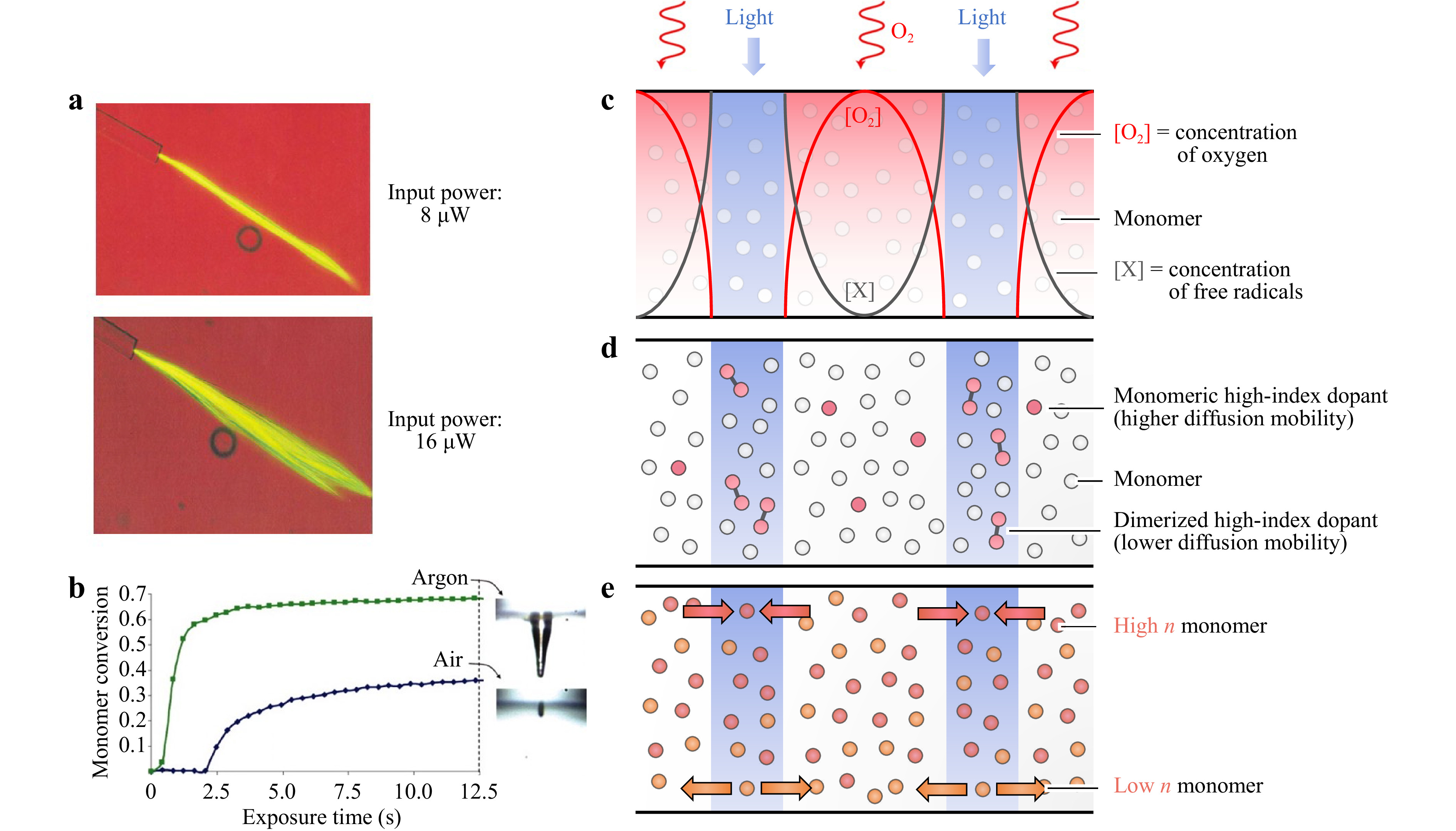
Fig. 2 Tuning index modulation by leveraging photopolymerization kinetics. a At high light intensities, SPPWs begin to break up into chaotic waveguides70. b Oxygen inhibition affects monomer conversion and the shape of the final waveguide (adapted from 49). c Photopolymerization can be carried out under high oxygen inhibition conditions to minimize off-target polymerization (adapted from71). d The reaction mixture can be doped with a high-index moiety that dimerizes under UV light, thus reducing diffusional mobility (adapted from77. e Index modulation can be achieved by the counter-diffusion of two monomers with different refractive indices (adapted from 42).
The impact of light intensity on the temperature of the reaction mixture is another important consideration. Polymers generally exhibit negative thermo-optic coefficients (
$ {dn}/{dT} $ ) because thermal expansion causes the refractive index to decrease. Zhang et al. evaluated a range of polymers used in optical waveguides and found that all exhibited a negative linear correlation between$ {dn}/{dT} $ and the coefficient of thermal expansion$ \alpha $ 72. Tolstik et al. found that this was pertinent to SPPW fabrication in PMMA films because high light intensities led to heating of the reaction mixture, producing a refractive index decrease that defocused the incident beam56, 64. This thermally induced increase in light divergence reduced the extent of self-focusing observed.Polymerization kinetics and waveguide formation are also influenced by oxygen quenching. Oxygen molecules inhibit free-radical polymerization by reacting with the radical species, thereby decreasing the concentration of initiator radicals in solution73. Higher oxygen concentrations in the reaction mixture correlate with longer induction periods before the onset of polymerization74. Soppera et al. compared pentaerythritol triacrylate (PETA) waveguides fabricated in oxygen atmospheres with waveguides fabricated in argon atmospheres. In the oxygen atmosphere, the induction period was longer, and the degree of monomer conversion was lower, giving rise to shorter and thinner waveguide tips. In contrast, polymerization rate was higher in the argon atmosphere and the waveguides were broader (Fig. 2b). The effect of inhibition on waveguide thickness was also raised by Jacobsen et al., who reported on a thiol-ene system for fabricating micro-scale trusses75. Unlike acrylates, the thiol-ene system has low susceptibility to oxygen quenching. Jacobsen et al. found that the waveguides thickened upon continuous exposure to light and speculated that additional inhibition was required to minimize undesirable thickening.
Chen et al. provided experimental confirmation for this hypothesis, showing that oxygen inhibition could be harnessed to one’s advantage to gain spatial control over self-focusing71. Micropillar arrays were fabricated via free-radical polymerization from trimethylolpropane triacrylate (TMPTA). Importantly, the reaction mixture was highly saturated with oxygen, ensuring that polymerization could not take place unless the photopolymer was sufficiently illuminated. This effectively set up ‘inhibition zones’, wherein regions outside of the light beam were strongly inhibited from undergoing polymerization. Only the irradiated regions could overcome the oxygen inhibition and photopolymerize (Fig. 2c). Chen et al. found that controlling the interplay between photoinitiation and oxygen inhibition conferred spatial control over SPPW formation. For example, higher intensities reduced the size of the inhibition zone and produced thicker pillars by liberating more free radicals into the irradiated areas71.
Carrying out photopolymerization under high-oxygen conditions is one of many strategies that leverage kinetics to achieve spatial control over photopolymerization. One approach is the use of non-migratory macrophotoinitiators which are themselves oligomeric or polymeric. Macroinitiators have limited diffusional mobility compared to small-molecule initiators76, which reduces off-target diffusion beyond the illuminated region. Therefore, photopolymerization is confined spatially to the irradiated region and no off-target chain initiation takes place. Chandross et al. proposed a similar approach for SPPW fabrication that involved doping the reaction mixture with a moderately volatile, high-index species77. Upon irradiation, the dopant can dimerize or polymerize within the irradiated region, with expected reduction in the diffusional mobility of the dopant. This approach prevents lateral diffusion of the dopant away from the irradiated zone, reducing off-target index modulation (Fig. 2d)77.
The diffusion of the monomer itself is also an important parameter for index modulation. Tomlinson et al. proposed an approach for augmenting index modulation by using a multi-monomer system78. The two monomers are chosen to have different refractive indices and a low tendency to copolymerize. Importantly, the higher-index monomer has a higher rate of polymerization than the low-index monomer. During irradiation, the more reactive, high-index monomer will be preferentially polymerized in the illuminated region. The local depletion of the high-index monomer from the irradiated region sets up a concentration gradient, causing more of the high-index monomer to diffuse in from the surrounding region. Conversely, low-index monomer diffuses away from the irradiated region. This counterdiffusion of the two monomers augments the index contrast between the irradiated and non-irradiated region, thereby enhancing self-focusing78 (Fig. 2e). Although this approach was first developed for volume holograms, Kagami et al. have since used multi-component systems to fabricate waveguides36. They used a high-index urethane-acrylate monomer which polymerized at 488 nm, and a low-index fluorine-epoxy monomer that did not polymerize at this wavelength. During waveguide fabrication, the reaction mixture was illuminated with light at 488 nm, allowing the high-index monomer to preferentially polymerize and accumulate within the irradiated zone36.
-
In the previous sections, we introduced various methods to increase the refractive index changes within polymerizing media as well as kinetic considerations that impact SPPW. Here, we continue to discuss examples of how to leverage polymerization kinetics for spatial control of SPPW morphology, as such precision affords greater range and geometric complexity of 3D-printed structures (e.g., arrays of freestanding micropillars).
Kagami et al. took advantage of a multi-component system to control the spatial orientation of cured photopolymer by selectively or sequentially curing monomers. Rather than specifically polymerizing the components of a blend to create a core-cladding morphology, other authors have used a process known as photopolymerization induced phase separation (PIPS) to direct the spatial orientation of multi-component systems. Photoreactive polymer blends are useful material systems to study and understand PIPS, although it has also been used to form structures in other systems such as micropores in polymer-solvents79, 80 or arrays in polymer with nanoparticles44, 45, 80. As irradiation facilitates polymerization and molecular weights increase, the system proceeds to a state of thermodynamic instability. This causes the monomers of miscible blends to separate into phases that are dominated by one of the two monomers. A study by Biria et al. comparing polymer blends consisting of epoxides and acrylates of different functionalities demonstrated the potential for using PIPS to create binary phases of monomers in a photopolymer81. It was later demonstrated repeatedly that the spatial arrangement of these phases can align with the light beam to achieve pillars of binary morphology41, 79, 82. This spatial correlation depends on a balance between PIPS and the opposing process of photo-crosslinking. In a study involving an acrylate and epoxide-terminated polydimethylsiloxane (PDMS) blend (which has a higher and lower refractive index, respectively), Biria et al. report that this balance between PIPS and crosslinking depends on both exposure intensity and weight fraction of the acrylate monomer41. More specifically, lower light intensity and lower weight fraction of acrylate allowed for the highest spatial correlation, with the acrylate forming the core (Fig. 3a). High light intensities favor crosslinking and limits phase separation, resulting in discontinuous phases, whereas low intensities allow phase separation to counter crosslinking. Lower weight fractions of acrylate require more polymerization to meet the threshold at which thermodynamic stability is reached and the blend experiences spinodal decomposition. At that point, however, the amount of polymerization is so high that viscosity soon inhibits further phase separation. This yields cylindrical pillars of binary morphology, where regions of beam irradiation become a continuous phase of the higher refractive index acrylate monomer while the lower refractive epoxide monomer constitutes the outside. Higher weight fractions can achieve this morphology; however, the opposing processes lead to degrees of distortion41. Biria et al. note in a related study that acrylate functionality can impact the extent of crosslinking, and therefore play a role in how these opposing processes interact81. Thus, there lies a delicate balance between crosslinking and PIPS in producing these structures in blends. There is also an implication that for PIPS to occur efficiently, the polymerization of the monomers within the core must occur at a faster rate than that of the surrounding sheath80. This is characteristic of studies where PIPS has been observed to create binary morphologies using acrylates (within the core) that polymerize faster than epoxide-terminated monomers (within the sheath)41, 81. It is still unknown whether the monomers must satisfy this condition and is a question for further study80. In sum, these findings suggest that one is most likely to achieve binary morphology in polymer blends if the following three conditions are met: (1) the monomer forming the core has a faster polymerization rate and higher refractive index than that of the monomer outside the core; (2) the blend has a low weight fraction of the core monomer; and (3) the blend is exposed to low light intensity41, 80. Taking advantage of PIPS to form this binary morphology is particularly useful because it results in a structure akin to an optical fiber. Since PIPS begins at the beginning of the fiber and proceeds throughout the photopolymer, it implies that this morphology can help to reinforce light self-trapping and waveguide formation. Although there is still work necessary to identify more specific parameters to achieve perfect spatial correlation, these studies highlight the potential to take advantage of PIPS and crosslinking dynamics to control morphology and potentially control waveguiding as well.
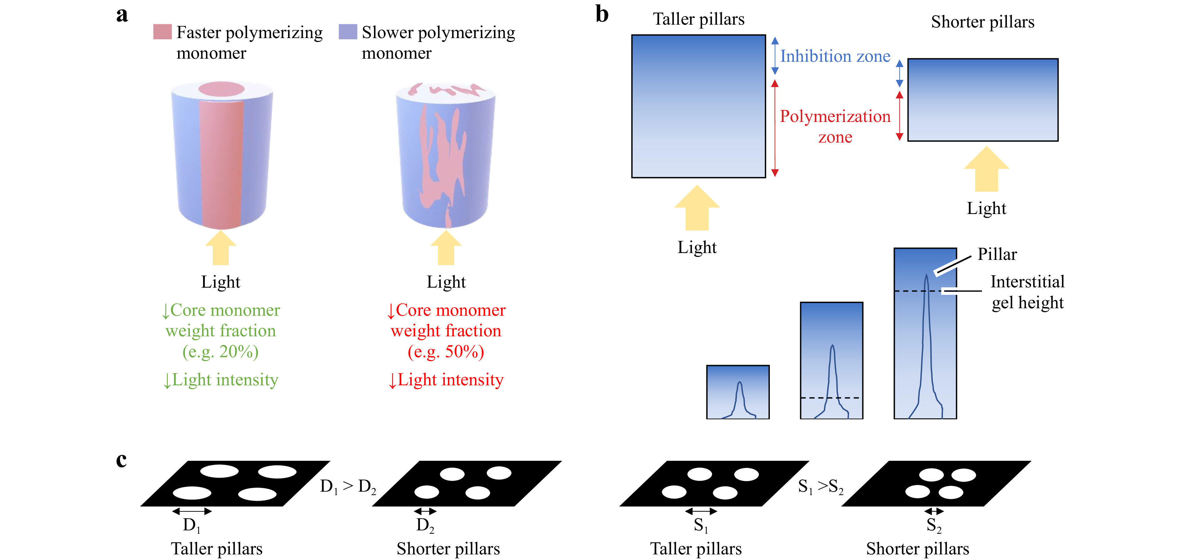
Fig. 3 Leveraging kinetics of photopolymerization for morphological control of printed structures. Examples of directing the final microscale morphologies of polymer structures fabricated by SPPW trajectories. a Balancing phase separation and photo-crosslinking can enable a binary morphology in polymer blends (image adapted from Raman spectroscopy data of Ref. 41. b Photopolymer thickness, aperture size, and aperture spacing impact curing depth. Curing depth can be increased by using greater photopolymer thickness, larger aperture diameters, and/or larger aperture spacing71, 83. With increasing photopolymer thickness, the inhibition zone is moved away from the site of light exposure. c Interstitial gel formation occurs above a photopolymer thickness threshold and also below an aperture spacing threshold. Such thresholds are dependent upon all of the aforementioned parameters as well as light intensity 71, 83.
Kinetics can also be leveraged for morphological control in single monomer systems. The choices made here can influence the resulting morphology of cured photopolymer without changing components of the photopolymer system. As previously mentioned, Chen et al. showed the ability to confer spatial control of TMPTA micropillar arrays made via SPPW fabrication under high-oxygen conditions, and how increasing light intensity generally increased the pillar height71. They also demonstrated that photopolymer thickness impacts multiple morphological features, including structure height (referred to here as a curing depth) and the presence of an interstitial gel layer. By varying the thickness between 0 and 3000 μm, the authors showed that the curing depth increased as the photopolymer thickness increased (Fig. 3b). To understand the justification, it is necessary to note that the arrays were fabricated under high oxygen conditions, where ambient air served as a constant source of oxygen at the air-photopolymer interface. Increasing the thickness moves the “inhibition zone” at the air-photopolymer surface away from the site of light exposure, allowing for greater curing depths. Li et al. came to the same conclusion, demonstrating that increasing photopolymer thickness leads to greater curing depths by moving up the inhibition zone83. Chen et al. reported that photopolymer thickness also dictated whether interstitial curing occurs between the pillars71. This gelation occurs when the balance between oxygen inhibition and photopolymerization (i.e., radical production) shifts to favor the latter and polymerization occurs outside of irradiated regions. This is likely because at larger thicknesses, oxygen is less able to sufficiently diffuse through the photopolymer to inhibit the formation of the gel83. Above a certain thickness threshold, polymerization between pillars is favored and a gel can form between pillars or even overtake the structures such that they become embedded (Fig. 3c). Below the threshold, oxygen permeation can still allow individual structures to form.
Photomasks can also be used to design and control the spatial orientation of waveguides and the pattern can impact the morphology of the cured photopolymer. Biria and Hosein explored how varying diameters D and spacing S of photomasked features enabling light transmission would impact the production of micropores in the surface of a photopolymer-solvent system35. They found that diameter and spacing of mask features determined the existence of random or patterned structures, overall porosity, and how easily these pores formed in photopolymer-solvent solutions. SPPW simulations produced by Belgacem et al. demonstrate that very closely spaced (10 μm) waveguides will elicit repulsive interaction forces, causing light to diverge from the anticipated projected path35. In situations where micropillar arrays are being formed via photomasks, the photomask pattern also impacts the final pillar height and morphology. Biria et al. predicted that beam size and spacing could impact the binary morphology of polymer blends due to crosslinking between closely spaced pillars and the hindrance of phase separation41. In their micropillar study, Chen et al. also showed that the curing depth and interstitial gel formation are dependent upon the diameter and spacing of the pillars, which is determined by the photomask71. They reported masks with greater diameter resulted in greater curing depths. This was attributed to larger aperture diameters allowing for more light to propagate through the polymerizing structure, thus having increased photoinitiation and radicals available at the tip to counter oxygen inhibition near the air-photopolymer interface. The spacing of structures also impacted curing depth, as the authors found greater spacing yielded greater curing depths. Although the fundamental mechanisms that led to these observations remain unclear, the empirical trend still points to the predictable tunability of final morphology (Fig. 3b) as well as the need for future studies that elucidate and predictably control this coupling.
Just as the formation of interstitial gel depends on photopolymer thickness, it also depends on the spacing of polymerizing structures. Masks with relatively greater feature spacing did not produce an interstitial gel for all tested photopolymer thicknesses; however, when the spacing of this mask was halved, the dependence on photopolymer thickness reappeared5. This dependence was attributed to lateral diffusion of radicals that can happen between consecutive polymerizing structures. Closely spaced structures are likely to have more radicals present between them and therefore have increased polymerization to yield the interstitial gel (Fig. 3c) A photomask with a high density is also at risk of the polymerized structures merging, therefore increasing the photopolymer thickness and altering the distribution of radicals and oxygen. Li et al. reported similar relationships between photopolymer thickness, photomask pattern, and curing depths. The authors found that each mask pattern had a unique range of photopolymer thicknesses necessary to create physically distinct, stable structures. Furthermore, they reported the general trend that thicker photopolymers, larger apertures diameters, and greater spacing all yielded greater curing depths83. Collectively, these studies demonstrate that curing depth can be controlled in part by photopolymer volume, and also show examples of how photomask patterns can confer a unique set of experimentally determined parameters or constraints (including light intensity) to achieve the formation of pillar arrays.
-
SPPW in photopolymeric materials encompasses several modules representing concurrent physical phenomena (Fig. 4a), whereby the overall fidelity of a simulation is reflected by the comprehensiveness of each component. To date, the models developed by various research groups appear to strongly capture a fraction of the physical phenomena prevalent in SPPW, while overlooking other important physics. There is a preeminent need for a complete model. This Section reviews computational models accounting for chemical reaction kinetics, light field, and wave propagation, which constitute the physical factors in SPPW.
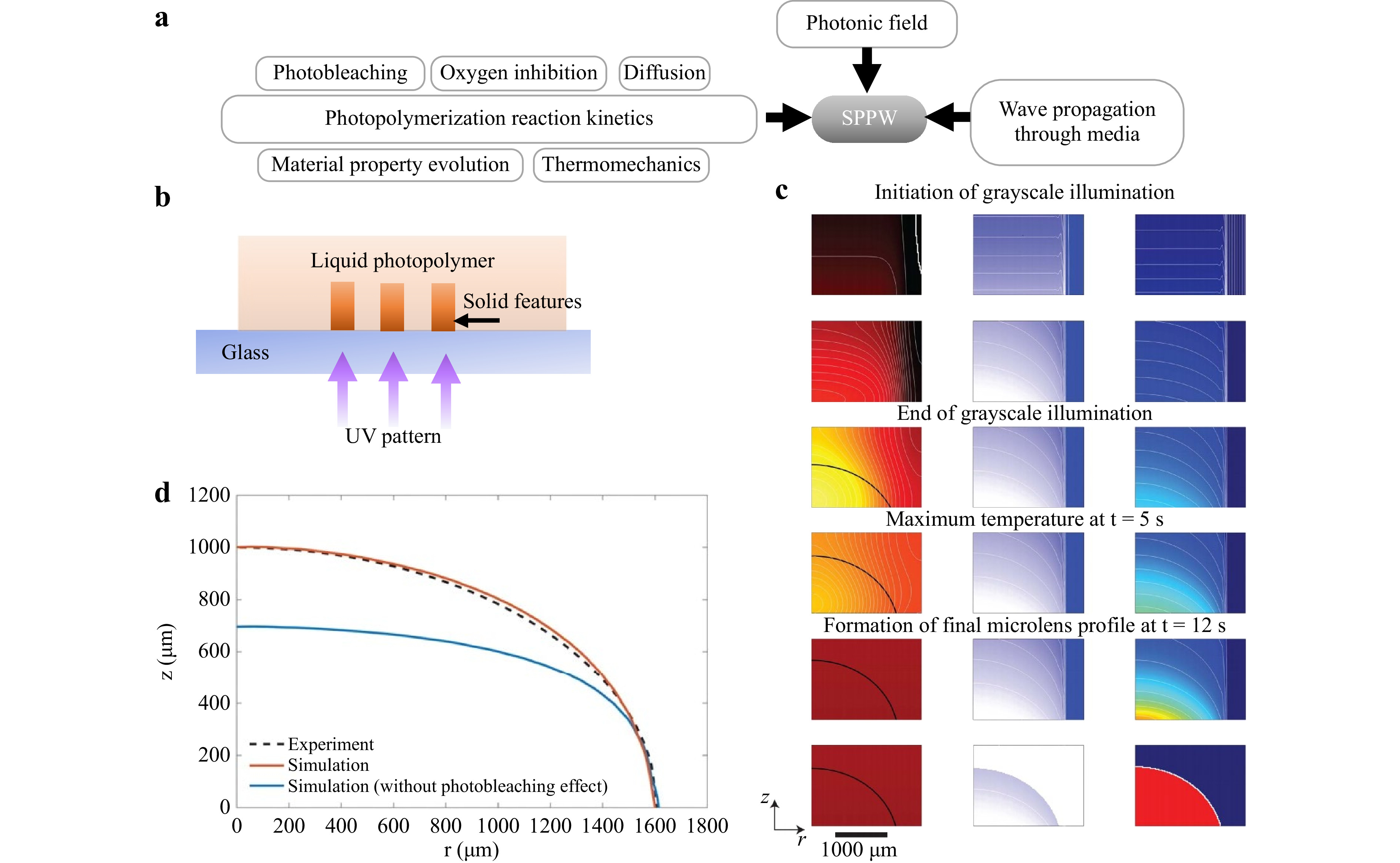
Fig. 4 Modeling components involved in light-based 3D printing or grayscale lithography processes relevant to SPPW. a Modular phenomena prevalent to the SPPW process. b Schematic of the crosslinking setup used in the grayscale lithography simulations presented in c and d. c Contour plots of the temporal evolution of temperature, initiator concentration, and degree of conversion fields, throughout a grayscale microlens fabrication process, at various time spots throughout the crosslinking process as labelled. The solidification front represents the gradual formation of microlens is shown by black solid lines in temperature contour plots91. d Cross-sectional geometry comparison of a fabricated aspherical lens with a radius of about 1620 μm. Dashed line and solid line represent the simulated profile with and without photobleaching, respectively65.
-
Most commonly, radical-mediated photopolymerization reactions are represented by differential equations that yield a dynamic concentration of reactant species including photoinitiator molecules In, free radicals generated by initiators R•, polymer chains, P, monomers, M, and oxygen, O2, each having dynamic concentrations as described mathematically in Eqs. 3−1284. The first step of the reaction is decomposition of photoinitiator molecules to each generate two radicals.
$$ In\stackrel{{k}_{d}}{\to }2R{\text •} $$ (3) The active radicals generated then react with monomers to create an active chain.
$$ R{\text •}\text+\text{M}\stackrel{{k}_{p}}{\to }P{\text •} $$ (4) Active polymer chains then react with available vinyl bonds on other active monomers and/or polymers to facilitate chain-growth, as well as crosslinking, particularly in polymers with multi-functional groups acrylates.
$$ P {\text •}+ M \stackrel{{k}_{p}}{\to }{P{\text •}} $$ (5) $$ P{\text •} + R{\text •} \stackrel{{k}_{p}}{\to }P\text{••} $$ (6) $$ P{\text •} + P{\text •} \stackrel{{k}_{p}}{\to }P\text{••} $$ (7) Mechanisms for reaction termination involves various ways including live radical termination via reaction with another radical or a radical on a chain to make dead polymer chains, Pdead, and dead radicals, Rdead, summarized as follows. Molecular weight-dependent termination may also be caused by steric hindrance in certain acrylate systems85.
$$ R{\text •}+R{\text •}\stackrel{{k}_{t}}{\to }{2R}_{dead} $$ (8) $$ P{\text •}+P{\text •}\stackrel{{k}_{t}}{\to }{P}_{dead} $$ (9) $$ P{\text •}+R{\text •}\stackrel{{k}_{t}}{\to }{P}_{dead} $$ (10) Within the reaction volume, oxygen acts as a radical scavenger that actively inhibits and hinders propagation.
$$ R{\text •} + {O}_{2} \xrightarrow{{k}_{t,oxy}}{R}_{dead} $$ (11) $$ P{\text •} + {O}_{2} \xrightarrow{{k}_{t,oxy}}{P}_{dead} $$ (12) The typical steps in photopolymerization, are commonly modeled by a set of ordinary differential equations (ODEs) as84
$$ \frac{d\left[In\right]}{dt}=-{k}_{d}\left[In\right] $$ (13) $$ \begin{split}\frac{d\left[R{\text •}\right]}{dt}=&2{k}_{d}\left[In\right]-{k}_{p}\left[M\right]\left[R{\text •}\right]-2{k}_{t}\left[P{\text •}\right]\left[R{\text •}\right]\\&-{2{k}_{t}\left[R{\text •}\right]}^{2}-{k}_{t,oxy}\left[{O}_{2}\right]\left[R{\text •}\right]\end{split} $$ (14) $$ \frac{d\left[M\right]}{dt}=-{k}_{p}\left[M\right]\left[R{\text •}\right]-{k}_{p}\left[M\right]\left[P{\text •}\right] $$ (15) $$ \frac{d\left[P{\text •}\right]}{dt}={k}_{p}\left[M\right]\left[R{\text •}\right]-{2{k}_{t}\left[P{\text •}\right]}^{2}-2{k}_{t}\left[P{\text •}\right]\left[R{\text •}\right]-{k}_{t,oxy}\left[{O}_{2}\right]\left[P{\text •}\right] $$ (16) $$ \frac{d\left[{P}_{dead}\right]}{dt}={{k}_{t}\left[P{\text •}\right]}^{2}+2{k}_{t}\left[P{\text •}\right]\left[R{\text •}\right]+{k}_{t,oxy}\left[{O}_{2}\right]\left[P{\text •}\right] $$ (17) $$ \frac{d{[O}_{2}]}{dt}=-{k}_{t,oxy}\left[{O}_{2}\right]\left[R{\text •}\right]-{k}_{t,oxy}\left[{O}_{2}\right]\left[P{\text •}\right] $$ (18) These constitutive equations were developed for monofunctional acrylates. Despite this limitation, they have been successfully adopted to model practical photopolymerization applications14, 30, 65, albeit without the ability to compute the concentration of polymer chains, dead or alive (P• or Pdead)84. The initiator decomposition rate constant term kd depends on the initial initiator concentration, light intensity, and penetration depth in the medium z, and is derived using the Beer Lambert law as86
$$ {I}_{abs}=2.3\in \left[In\right]{I}_{0}{e}^{\left(-2.3\in \left[In\right]z\right)} $$ (19) $$ {{k}_{d}=\varnothing I}_{abs}\left(\frac{\lambda }{{N}_{A}hc}\right) $$ (20) where [In] is the initiator concentration, I0 is the incident intensity, Iabs is the absorbed intensity integrated up to depth z, λ is the wavelength of the light in nanometers, NA is Avogadro’s number, h is Planck’s constant, c is the speed of light, φ is the quantum yield of initiation indicating the initiation efficiency of a radical (typically 0.6 for most photoinitiators), and ε is the molar absorptivity of photons for a given initiator (experimentally determined)86. This rate constant kd is typically determined experimentally from the half-life of the initiator and ranges 10−3-10−1 mol·s·m−3 in Ref. 86.
-
The mobility of reaction species (e.g., free radicals) diffusing through the liquid photopolymer to neighboring regions greatly affects the reaction and is thereby included in most models with rate parameters often empirically obtained. Photopolymerization is initially reaction rate-controlled in the liquid state before switching to a diffusion rate-controlled mode at the onset of the phase-change induced by crosslinked network formation toward solidity. Diffusion-controlled reactions terminate when the mobility of the large growing polymer chains is hindered. The diffusion-limited rates of propagation and termination are represented by critical free volume parameters, fcp and fcp, captured in the following relations for the propagation and termination rate constants kp and kt, respectively,
$$ {k}_{p}=\frac{{k}_{p0}{e}^{\left(-{E}_{T}/RT\right)}}{1+{e}^{\left({A}_{p}\left(\frac{1}{f}-\frac{1}{{f}_{cp}}\right)\right)}} $$ (21) $$ {k}_{t}={k}_{t0}{e}^{\left(-{E}_{T}/RT\right)}{\left(1+\frac{1}{\dfrac{{R}_{rd}{k}_{p}\left[M\right]}{{k}_{t0}{e}^{\left(-{E}_{T}/RT\right)}}+{e}^{\left({-A}_{t}\left(\frac{1}{f}-\frac{1}{{f}_{cp}}\right)\right)}}\right)}^{-1} $$ (22) where kp0 and kt0 are the pre-exponential factors for the true kinetic constants87. When the fractional free volume of the system f is greater than the critical free volume fct, the reaction is diffusion controlled. The constants Ep, Et, Ap, At, and Rrd are specific to the monomer used and are obtained typically using differential photocalorimietry (DPC). Eqs. 19, 20 can be independently isolated at various conversion levels using continuous and flash exposure experiments in the configuration shown in Fig. 4b88. The double bond conversion, ɑ, of multifunctional monomers, is computed using
$$ \frac{d\left[M\right]}{dt}={k}_{p}\sqrt{\frac{{k}_{d}\left[In\right]}{2{k}_{t}}}\left[M\right] $$ (23) $$ \alpha =\frac{{\left[M\right]}_{0}-\left[M\right]}{{\left[M\right]}_{0}} $$ (24) where [M] represents the concentration of monomers in the system which is to be multiplied by the number of functional groups when computing double bond conversion. The rate of polymerization depends on the initiation rate on a square root basis65. The workflow for ODE model development is: (i) determine molar absorptivity, ε, to be used in initiator decomposition, (ii) estimate
$ {k}_{p}/\sqrt{{k}_{t}} $ from in situ Fourier-transform infrared spectroscopy (FTIR) data of deoxygenated monomer-initiator system of interest, (iii) estimate kp, kt, and kt,oxy via fits to the ex situ FTIR data, and (iv) determine the critical conversion value that marks the threshold between liquid and gel/solid states, typically assisted by gel time micro-rheology based on the premise of rapid change in the viscosity of a crosslinking polymer84, 89. The polymerization rate Rp, cure depth Cd, penetration depth Dp, and critical energy needed for the onset of gelation Ec, are derived using the Beer-Lambert law as follows84, 90.$$ {R}_{p}=\frac{{C}_{0}{e}^{\left(-\frac{{E}_{c}}{RT}\right)}}{1+{e}^{\left(\frac{1}{f}-\frac{1}{{f}_{cp}}\right)}}\left[M\right]\sqrt{E} $$ (25) $$ {C}_{d}={D}_{p}ln\left(\frac{E}{{E}_{c}}\right) $$ (26) $$ {D}_{p}=\frac{1}{2.3\in \left[In\right]} $$ (27) $$ {E}_{c}=\left(\frac{2.3\in \varnothing {N}_{A}hc}{\lambda t}\right){\left(\frac{-ln\left(1-{\propto }_{c}\right)}{{k}_{p}/\sqrt{{k}_{t}}}\right)}^{2} $$ (28) where E is the maximum energy delivered to the photopolymer, t is irradiation time, C0, a monomer-specific constant, Ec, and fcp are measured experimentally; f is the number of functional groups. The versatile modeling framework presented captures the effects of process parameters such as initiator concentration, light intensity, and exposure time on the cure depth, with and without the effects of oxygen inhibition. Such models have been utilized in two- or three-dimensional multi-physics models to predict the shapes and dimensions of fabricated parts via light-based 3D printing or grayscale lithography, in which monolayer photopolymerization created using a grayscale digital mask in a single flash of exposure can produce microlens arrays (MLAs) or other optical components14, 32, 65, 91.
-
Linking photopolymerization conditions to physical properties of the material enables capturing of shrinkage and warpage due to inhomogeneity90, 92, and has been overlooked in many modeling attempts. As was discussed in Section 2, thermal expansion and shrinkage strongly affect the degrees of refractive index change and self-focusing/self-trapping. Thermo-mechanics of photopolymerization, an exothermic reaction, can be included using energy conservation relations such as
$$ \rho {C}_{p}\frac{\partial T}{\partial t}+\overrightarrow{\nabla }\left(-k\overrightarrow{\nabla }T\right)={R}_{p}\Delta H\left(\in \left[In\right]E\right) $$ (29) where ρ represents density, Cp is the heat capacity at constant pressure, k is the thermal conductivity, and
$ \Delta H $ is the enthalpy change of the reaction. The momentum conservation gives$$ \rho \frac{\partial \overrightarrow{u}}{\partial t}+\overrightarrow{\nabla }{\underset{\_}{\sigma }}^{T}=0 $$ (30) where
$ \overrightarrow{u} $ is the displacement and$ \underset{\_}{\sigma } $ is Cauchy’s stress90. Photopolymerization contributes to two types of strain: (i) thermal expansion due to the temperature change; and (ii) isotropic shrinkage due to crosslinking that linearly depends on the degree of conversion. Mechanical properties of photopolymers (idealized as isotropic and linear elastic) are also used as inputs in the model. For instance, the shear storage modulus is adopted as$$ G={G}_{mono}+\frac{{G}_{poly}}{1+{e}^{\left(-\kappa \left(p-{p}_{half}\right)\right)}} $$ (31) where
$ {G}_{mono} $ and$ {G}_{poly} $ are the shear modulus of the monomer and polymer, respectively,$ {p}_{half} $ is the half-conversion shear modulus equal to half of$ {G}_{poly} $ , and$ \kappa $ is a shape control parameter, all obtained experimentally via in situ rheometry90. Additionally, the effects of residual stresses can be captured by incorporating a plastic model including a yield stress parameter to improve the agreement between the model and experiments30,90. Recently, temporal evolution of temperature was modeled in a two-dimensional plane alongside initiator concentration and degree of conversion for grayscale lithography of microlens arrays91 (Fig. 4c, d). -
Many routinely used photoinitiators exhibit photobleaching (PB) effects, described as weaker light absorption by photoinitiator products compared to the original photoinitiator molecule. Inclusion of photobleaching effects in the model is critical to obtaining a physically correct light intensity distribution within the photopolymer that directly affects the crosslinking outcome. Photobleaching allows more light to pass through the system, as consumption of the photoinitiator leads to an increase in light intensity within underlying material field93, creating a light intensity gradient in the sample that depends on time and penetration depth into the reaction volume. Immediately after irradiation, initiators will be consumed at a rate proportional to the local light intensity that is represented by the Beer-Lambert law. The coupling of light intensity gradient and initiator concentration gradient adds complexity to mathematical modelss94, 95, whereby the generalized description of the spatial and temporal evolution of photobleaching systems consist of the following governing differential equations
$$ \frac{\partial {C}_{i}\left(z,t\right)}{\partial t}=-{\varepsilon }_{i}{\varphi }_{i}\left(\frac{E\left(z,t\right)}{{N}_{A}hv}\right){C}_{i}\left(z,t\right)+{D}_{i}\frac{{{\partial }^{2}C}_{i}\left(z,t\right)}{\partial {z}^{2}} $$ (32) $$ \frac{\partial {C}_{p}\left(z,t\right)}{\partial t}={\varepsilon }_{i}{\varphi }_{i}\left(\frac{E\left(z,t\right)}{{N}_{A}hv}\right){C}_{i}\left(z,t\right)+{D}_{p}\frac{{{\partial }^{2}C}_{p}\left(z,t\right)}{\partial {z}^{2}} $$ (33) $$ \frac{\partial E\left(z,t\right)}{\partial z}=-\left({\varepsilon }_{i}{C}_{i}\left(z,t\right)+{A}_{m}+{\varepsilon }_{p}{C}_{p}\left(z,t\right)\right)E\left(z,t\right) $$ (34) where
$ {C}_{i}\left(z,t\right) $ represents the initiator molar concentration at depth z and time t,$ {C}_{p}\left(z,t\right) $ is the photolysis product molar concentration,$ E\left(z,t\right) $ is the incident light intensity,$ {\varepsilon }_{i} $ and$ {\varepsilon }_{p} $ are the initiator and photolysis product molar absorptivities, respectively,$ {D}_{i} $ and$ {D}_{p} $ are the diffusion coefficients of the initiator and photolysis products, respectively, and$ {A}_{m} $ is the absorption coefficient of the monomer. Solving the differential equations using the finite differences method yields plots of initiator concentration as a function of sample depth at various exposure times. In general, photobleaching profoundly increases with increasing initiator concentration as well as with exposure times (short exposures were found to minimize the effect)94. Moreover, increased molar absorptivity of the initiator leads to higher rates of photobleaching, and diffusion was found to have a negligible effect in most photobleaching systems, as the diffusional timescale is large relative to that of photoinitiation94. -
Accurate replication of the multiple physical processes simultaneously at play during the SPPW process inherently demands complex computational models. Prediction of a cured 3D profile strongly depends on coupled factors that add complexity to the process, e.g., oxygen inhibition, photobleaching, photo-trapping, self-focusing, and shrinkage30, all of which can change the shape of a patterned feature. Multi-physics models can be used to simultaneously solve the constitutive equations governing the chemical reaction, structural mechanics, and heat transfer modules. Overlooking any physical phenomena has been observed to produce substantial inaccuracies in semi-empirical process models 32, 93, 95. Recently, modeling schemes were modified to include an additional step of initiator self-dissociation to effectively capture photobleaching and thereby better-predict the resulting cross-sectional profile of micro-lenses (Fig. 4d)65.
Accurate replication of the light intensity profile within a single pixel of an illuminated image can enhance the model’s predictive accuracy. In a 3D-printing application utilizing a DMD/DLP as a spatial light modulator, the illumination of light on a surface is represented by an intensity distribution model obtained using ray-tracing methods or utilizing a point spread function (SPF), which assumes Gaussian distributions to approximate the intensity of a pixel corresponding to a micromirror on the DMD chip65, 96. The intensity distribution of a pixel is described as a first-order approximation as97, 98.
$$ H\left({x}_{i},{y}_{j}\right)={H}_{0}{e}^{-\left(\frac{2}{{\omega \left({x}_{i},{y}_{j}\right)}^{2}}\right){r\left({x}_{i},{y}_{j}\right)}^{2}} $$ (35) where
$ H\left({x}_{i},{y}_{j}\right) $ is the light intensity distribution and$ {H}_{0} $ is the peak intensity at the center of a pixel,$ r\left({x}_{i},{y}_{j}\right) $ is the distance from the center of the pixel$ \left({x}_{i},{y}_{j}\right) $ ,$ \omega \left({x}_{i},{y}_{j}\right) $ is the directional Gaussian half-width of the intensity distribution. In the work of Emami65, the Beer-Lambert light intensity distribution was modified to account for initiator consumption as a function of depth and time as$$ {I}_{z}\left(x,z,t\right)={I}_{s}\left(x,t\right){e}^{-2.3\in {\int }_{0}^{z}\left[In\right]\left(x,z,t\right)dz} $$ (36) where Is is the incident light intensity at the boundary of the reaction volume and
$ \left[In\right]\left(x,z,t\right) $ is the molar concentration of absorptive initiator at location x, depth z, and time t. These measurements were coupled to the chemical reaction ODE solver within COMSOL to generate the predictive 2D planar model in Fig. 4d for a height of up to about 1 mm65. Recently, the volumetric light field generated by a DMD/DLP light engine was implemented, and it was found that the model without incorporating volumetric light field was still able to predict part height with the same accuracy, albeit with reduced precision in surface roughness91. In summary, multi-phase models provide a strong foundation for accurate representation of the photopolymerization process induced by well-defined, high-resolution light patterns, with room for improvement through inclusion of self-trapping and self-focusing effects. The models described so far in Section 3 were developed relatively recently for light-based 3D printing and photolithography applications and did not primarily aim to focus a narrow beam of light through the photopolymer media through self-focusing, and therefore did not include nonlinear wave equations to capture the dynamic formation of self-trapping filaments, which are described in the following Section. -
Much of the fundamental nonlinear wave equation modeling for self-trapped beams is based on work starting in the 1960s and is often partially neglected in recent works. Existing models for laser-based SPPW processes adopt simplified photopolymerization modules and are therefore incomplete in that the nonlinear propagation loss that is characteristic of photoabsorptive photopolymers remains uncaptured. Though numerical analyses of the nonlinear wave equation showing the dynamic formation of self-trapping filaments have been developed since the 1960s99, 100, there is a gap in their direct implementation for practical process models for manufacturing applications. Predictive modeling of SPPW is inherently complex due to interaction of multiple physical mechanisms and requirement to capture phnenomena over both short and long timescales. Various numerical models presented thus far generally account for light-wave propagation using beam propagation methods (BPM) using two partial differential equations and refractive index change due to photopolymerization. It has been shown that light beams can only be self-trapped in photopolymers given sufficiently low average intensities25. In other words, a unique feature of self-trapping as a nonlinear optical effect is its slow time response observed only at sufficiently low average optical intensities. The index change in a photopolymer is typically modeled by the nonlinear wave equation describing the dependence of refractive index and absorption on optical exposure. Empirically, the refractive index n response to an optical field amplitude F which is proportional to the intensity of the optical field is of the form25
$$ \Delta {n}^{\text{'}}\left(x,y,z,t\right)=\Delta {n}_{0}^{\text{'}}\left(1-{e}^{-\frac{1}{{U}_{0}}{\int }_{0}^{t-\tau }{\left|F\left({t}^{\text{'}}\right)\right|}^{2}d{t}^{\text{'}}}\right) $$ (37) where
$ \tau $ is the initiator radical lifetime (the lag between irradiation and index response) and U0 denotes the critical exposure needed to induce polymerization, which was used to develop the numerical simulations shown in Fig. 5a. The equation implies proportionality between the magnitude of refractive index change, or rate of polymerization, and optical intensity55. An intense illumination leads to imminent creation of many radicals, shortening the overall radical lifetime,$ \tau $ , completely curing the photopolymer before the optical beam experiences an index change. The index change response lags by 0.01-1 s relative to the irradiation, reducing in the absence of oxygen inhibition16. As the beam propagates, the refractive index near the axis rises at first, then becomes saturated. The resultant induced convex lens tends to focus incoming, still nearly parallel, rays into a ring100. The bent rays continue inward and form a central maximum, after which the intensity in the ring continues to rise until a new flat region is formed in the induced lens, where a new ring begins to form. This explains regions of high intensity separated by low intensity zones. In Fig. 5a the leftmost result illustrates the beam propagation before any index change (showing non-self-focused/trapped diffusion), then self-trapping becomes apparent after the critical incubation period, demonstrating weak oscillations in beam diameter that is typical of trapped beams, also consistent with the bead on filament formation in Fig. 5b99. Longer exposures create an array of solid pillars with larger diameters25 that remain uniform in diameter well beyond the confocal parameter of the Gaussian input beam.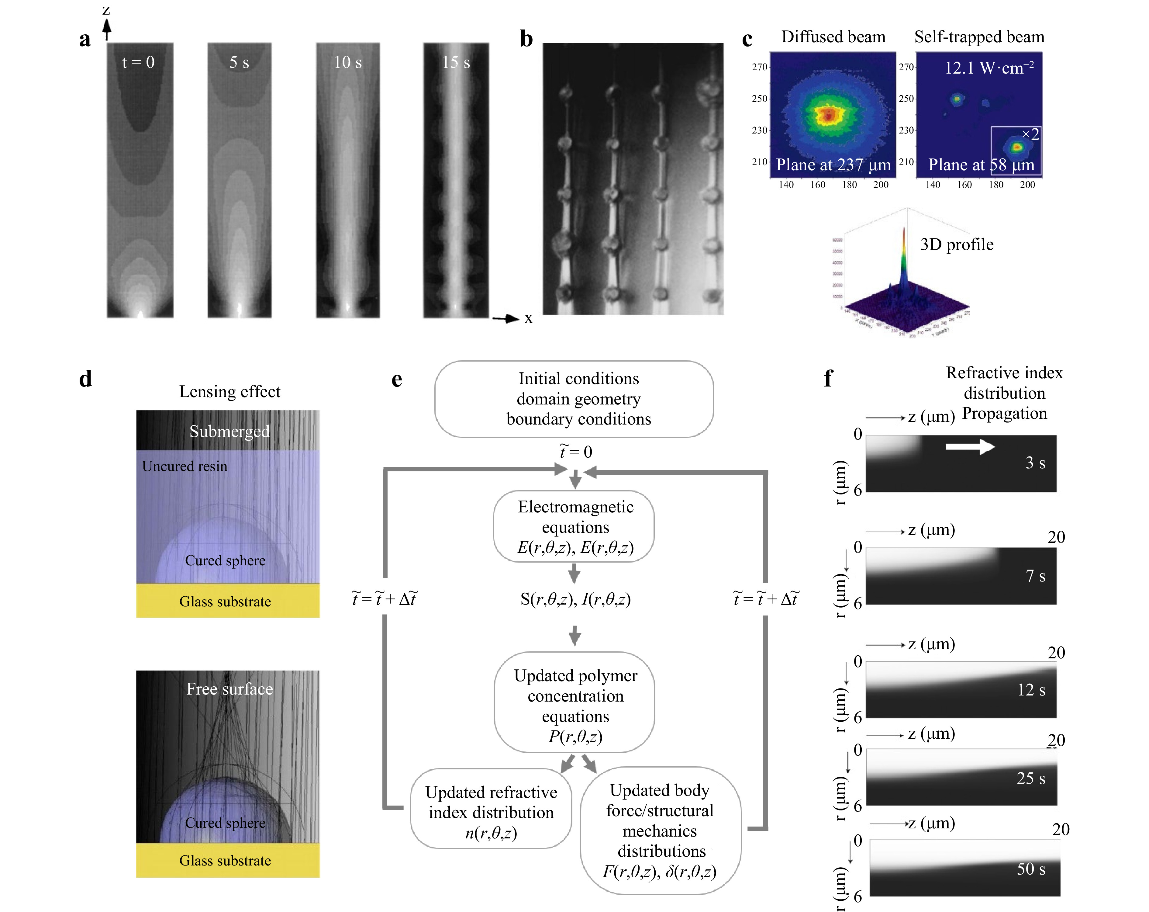
Fig. 5 Modeling of self-trapped beam propagation in a photopolymer. a Numerical simulations of beam propagation in a photopolymer25. b Pillars of 200 μm diameter formed by a self-trapped UV beam25. c Two- and three-dimensional light intensity profiles of diffracted and self-trapped beams of white light at 12.1 W-cm−2 in an organosiloxane-based photopolymer. d Comparison of light path when curing through a cured region, with and without presence of photopolymer, and changes in refractive index as a function of cured region height95. e Flowchart of a multi-physics SPPW model101. f Grayscale plot of index of refraction distribution at various time steps.
The experimental measurements shown in Fig. 5c demonstrate collimated white light (400-800 nm, 2.7-22 W·cm−2) with its focal plane at the entrance of an organosiloxane-based monomer without an initiator exhibited a broad diffraction, characteristic of white light with random phase fluctuations (i.e., incoherence)55. Upon dissolution of Irgacure 784 photoinitiator, the broad beam narrowed in both transverse directions into a focused peak, apparent in the three-dimensional profile in Fig. 5c, and near-identical spatial profiles of self-trapped beams were observed for all intensities even after 6 mm of propagation55. The three physical stages, consistent with the measured spatial and temporal beam evolution, involved (i) self-focusing, where the beam produces a refractive index gradient causing a rapid decrease in beam width and efficiency; (ii) self-lensing of the beam leading to beam divergence supression; and (iii) refractive index changes as methacrylate groups are depleted by photopolymerization where the refractive index becomes uniform55. Further characterization of the self-lensing effect has been conducted utilizing ray-tracing simulations to verify beam deflection induced by cured regions95. The optical test simulation in Fig. 5d, performed with and without the presence of a liquid photopolymer, shows that the small change in refractive index between the solid and liquid photopolymer (in this case Dn = 0.0133), did not focus the rays in the submerged condition95.
Another common modeling approach is the finite element method with advantages such as efficient incorporation of photopolymer shrinkage on refractive index that affects propagated modes as well as incorporation of complex initial geometries. As outlined in the flowchart of Fig. 5e, the initial conditions defined by the refractive index, n, and normalized polymer concentration,
$ \tilde{P} $ , are used in each time-step to solve electric E, and magnetic H fields computed from the power flow Sz and intensity Iz in the direction of propagation for the time interval$ \nabla t $ . The change in photopolymerization step,$ \nabla \tilde{P} $ , is used to update refraction index change and shrinkage distributions through density changes in each time-step. Light wave propagation through a photopolymer is typically modeled following 3D vectorial wave equations in terms of E and H fields as101.$$ {\mu }_{0}\frac{\partial }{\partial t}\left({\in }_{0}{\left[n\left(r,\theta ,z,t\right)\right]}^{2}\frac{\partial E}{\partial t}\right)+\nabla \times \left(\nabla \times E\right)=0 $$ (38) $$ {\mu }_{0}\frac{\partial }{\partial t}\left({\in }_{0}{\left[n\left(r,\theta ,z,t\right)\right]}^{2}\frac{\partial H}{\partial t}\right)+\nabla \times \left(\nabla \times H\right)=0 $$ (39) where
$ {\mu }_{0}=4\pi \times {10}^{-7} $ and$ {\in }_{0}=8.8542\times {10}^{-12} $ . The phenomenological model to describe the dynamics of index change during photopolymerization is as follows102$$ \frac{\partial }{\partial t}\frac{\Delta n}{n}={\left({E}_{0}{E}_{0}^{*}\right)}^{p*}\left[1-\frac{\Delta n\left(r,t\right)}{\Delta {n}_{s}}\right] $$ (40) where
$ {E}_{0} $ is the electric field amplitude, p* = 1 for single-photon absorption, and$ \Delta {n}_{s} $ is the total change in index after saturation. Photopolymerization rates are calculated through the chemical reaction models presented in Section 3.1. A local time variable s is defined to incorporate the spatial variations in$ \tilde{P} $ at any time step. Once the photopolymerization state has been calculated, the index and density distributions are updated through the model domain as$$ \Delta n\left(r,\theta ,z\right)={\alpha }_{1}{S}_{z}\left(r,\theta ,z\right)\frac{d\stackrel{~}{P}}{d\stackrel{~}{s}}\left(r,\theta ,z\right)\Delta \stackrel{~}{s} $$ (41) where the constant
$ {\alpha }_{1} $ governs the difference between maximum index difference between fully cured photopolymer and uncured photopolymer. Density changes and consequent shrinkage is tracked using classical linear elastic solid mechanics equations for the finite element method as$$ \nabla \cdot\sigma +F=0, $$ (42) over the region of the photopolymer bath, where
$ \sigma $ denotes the stress tensor and F represents the body force in the region. For small deformations, the compressive pressure p required to achieve an equivalent volume change after complete photopolymerization is$$ p=\frac{\left(\dfrac{V\left(0\right)-V\left(t\right)}{V\left(t\right)}\right)E}{3(1-2\upsilon )} $$ (43) where E is the Young’s modulus of elasticity and
$ \upsilon $ is the Poisson’s ratio103. This relation is captured in the following equations which relate the body field to polymerization throughout the photopolymer for each time step as$$ {F}_{r}\left(r,\theta ,z\right)={-p}_{0}\stackrel{~}{P}(r,z,s) $$ (44) $$ {F}_{z}\left(r,\theta ,z\right)={-p}_{0}\stackrel{~}{P}(r,z,s) $$ (45) Assuming a Gaussian light distribution and adopting Lagrange-quadratic elements to mesh the domain and sufficiently small time-steps to avoid numerical wave attenuation, the axisymmetric results in Fig. 5f show that the formation of polymerization begins in a tapered region that propagates to a steady-state beam in three stages: (i) a slow beginning of the photopolymerization initiation of up to 4 s, (ii) rapid increase in
$ \Delta n $ due with chain-growth and light-wave focusing, and (iii) a saturation stage leading to generation of a stable beam. It was also found that polymer shrinkage occurred primarily in the Z-direction. Shrinkage shortened the length of the polymerized strut and increased the tapering angle and cross-sectional profile of the initial region of the feature.The formulation for the evolution of refractive index expressed in Eq. 40 is unable to capture the more complex, non-monotonic index profile observed in SPPW experiments47. In response to this need, the model of Belgacem et al.35 was developed addresses this using a model that describes the index evolution based on photopolymerization kinetics as
$$ \frac{\partial M(r,t)}{\partial t}=\nabla \cdot \left(D\nabla M\left(r,t\right)\right)-kM\left(r,t\right)I\left(r,t\right)\left(1-\frac{\Delta n\left(r,t\right)}{\Delta {n}_{f}}\right) $$ (46) $$ \frac{\partial P(r,t)}{\partial t}=kM\left(r,t\right)I\left(r,t\right)\left(1-\frac{\Delta n\left(r,t\right)}{\Delta {n}_{f}}\right) $$ (47) where M and P represent the volume fractions of the monomer and polymer, respectively, D is the diffusion coefficient, and
$ {n}_{f}={n}_{p}-{n}_{m} $ with$ {n}_{p} $ and$ {n}_{m} $ as refractive indices of the monomer and polymer, respectively. The variation of monomer and polymer concentrations are also accounted for by considering the molar linear polarizabilities via Lorentz-Lorenz relation104$$ \frac{{n}^{2}-1}{{n}^{2}+2}=M\frac{{n}_{m}^{2}-1}{{n}_{m}^{2}+2}+P\frac{{n}_{p}^{2}-1}{{n}_{p}^{2}+2}+A\frac{{n}_{a}^{2}-1}{{n}_{a}^{2}+2} $$ (48) where na and A denote the refractive index volume fraction of other chemical species that do not undergo modification during photopolymerization (e.g., photoabsorber or co-initiator). Congruent with prior experiments, the simulations (Fig. 6a) showed a strong dependence on the initial monomer concentration and light intensity product. This represents a progressive transition from filamentation to a defined optical channel confining a single propagation mode. The simulations could also predict the interaction of counter-propagating SPPW waveguides used for the fusion of optical fibers without strict initial alignment conditions, marked by a deviation of the trajectory of the spatial solitons (Fig. 6b).
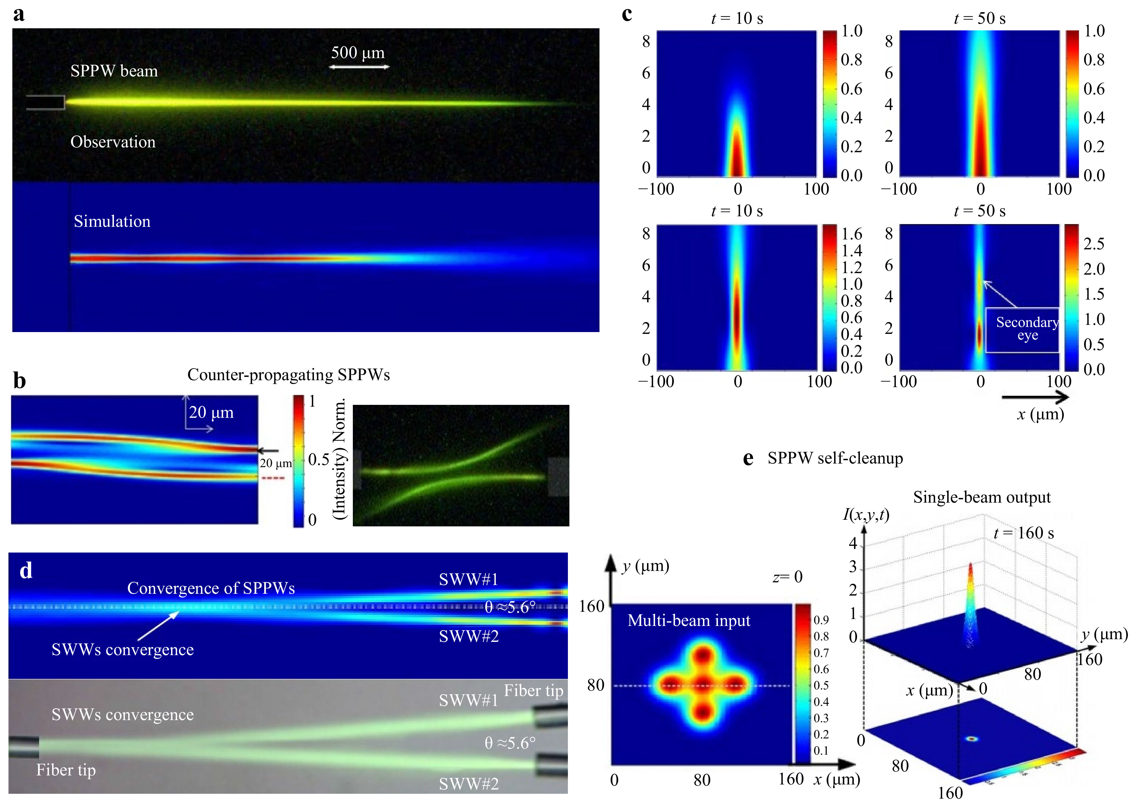
Fig. 6 Simulations of self-trapped beams in photopolymers. a Observation and simulation of an SPPW beam in a photopolymer system35. b Simulation and microscopy of anti-crossing interaction of two counter propagating SPPW waveguides with a lateral shift of 10 μm offset and with diffusion at the beginning and end of propagation35. c Numerical predictions of the normalized light intensity distribution at various exposure times34. d Two beams converge to create a single self-trapped beam within a photopolymer at an angle about 5.6°106. e Initial and output beam profiles demonstrating the self-cleanup effect of SPPW107.
In contrast to classical finite element modeling approaches, many of the SPPW models follow the pseudo-spectral method to achieve the same accuracy at up to an order of magnitude faster computational time, utilizing dimensionless transverse coordinates and normalization of time and propagation distances. In this realm, the split-step Fourier method is used as the main algorithm applied to the differential equations describing the light propagation problem. In one example, a model represented the light propagation component by combining electric field expression into the paraxial wave equation to give105
$$ i{k}_{0}{n}_{0}\frac{\partial E}{\partial z}+\frac{1}{2}{\nabla }^{2}E+{k}_{0}^{2}{n}_{0}\Delta nE+\frac{i}{2}{k}_{0}{n}_{0}\alpha E=0, $$ (49) treated by the simplification of neglecting high-order derivatives of the electric field, leading to34
$$ \frac{\partial E}{\partial z}=\frac{i}{2{k}_{0}{n}_{0}}{\nabla }_{\perp }^{2}E+i{k}_{0}\Delta nE-\frac{1}{2}\alpha E, $$ (50) where
$ {\nabla }_{\perp }^{2}={\partial }^{2}/\partial {x}^{2}+{\partial }^{2}/\partial {y}^{2} $ ,$ \alpha $ is the absorption parameter, and$ {k}_{0}=2\pi /\lambda $ is the wave number. This model successfully captured the primary and secondary ‘eye’ formation in both low- and high-dye concentration simulations (Fig. 6c). Increasing exposure time from 10 to 100 s, the incident light initially diffracts as it propagates through the homogenous material as index changes do not occur instantaneously. At first, the highest intensity peak is at the input face closest to the source, which gradually shifts forward upon self-trapping at later time-steps and begins to migrate away beyond 200 s to form the secondary ‘eye’. At higher dye concentrations exhibiting higher nonlinear absorption, index change-induced self-focusing is initially weak and insufficient to compensate for diffraction until photoabsorbing components are consumed by the onset of photobleaching. Using this pseudo-spectral approach, simulations have been developed to validate experimental SPPW convergence and coupling (Fig. 6d) and the corresponding optical/power gains and losses106, multimode fiber (MMF) laser beam ‘self-cleanup’ whereby a multi-channel structured beam shape can merge to form a single-channel Gaussian-like beam for sufficiently large index changes and strong dye photoabsorption (Fig. 6e)107.Table 2 summarizes that, among the models presented thus far, many lack comprehensive components of the SPPW process. These limitations include use of simplified photopolymerization kinetics equations34, 106, 107, overlooking the photobleaching effect34, 105, 107 or the Lorentz-Lorenz molar linear polarizabilities relation34, 107. Such simplifications limit predictability needed to design better materials and processes for 3D printing of complex polymeric structures via SPPW, and thus prompt development of accurate multi-physics models integrating all components of the process with sufficient generality, hence applicable to a range of materials as well as light source characteristics. This is necessitated by the need for predictive models that give precise control over not only the final printed dimensions of self-trapped polymeric features, but also predict effective stiffness and warpage along the printed array.
Ref. and year of publication Model type Chemical reaction module Oxygen inhibition module Photobleaching module Species diffusion module Thermomechanics module Material property evolution module Volumetric light-field module Beam propagation and
index-change moduleApplication 202191, 108 Finite element method (FEM) √
Modeled first-order constitutive ODEs√
Modeled; improved oxygen inhibition√
Modeled, added self-dissociation equation√
Modeled√
Modeled√
Modeled√
Modeled DMD light field×
Not modeledGrayscale microlens fabrication 201782 Spatial discretization, commercial beam propagation software √
Simplified model with steady-state approximations×
Not modeled×
Not modeled√
Modeled×
Not modeled×
Not modeled√
Modeled for laser source√
ModeledSelf-trapping of lasers 201084,
201195,
201332Unspecified √
Modeled first-order constitutive ODEs√
Modeled
empirically
94, 109×
Not modeled√×
Limited to oxygen diffusion only×
Not modeled×
Not modeled√×
Limited to basic light intensity profile×
Not modeledChemical reaction model development 201865 FEM √
Modeled first-order constitutive ODEs√
Modeled; improved oxygen inhibition√
Modeled, added self-dissociation equation√
Modeled×
Not modeled×
Not modeled√×
Limited to planar pixel representation×
Not modeledGrayscale microlens fabrication 201830 FEM √
Modeled first-order constitutive ODEs√
Modeled×
Not modeled√
Modeled√
Modeled volume shrinkage and internal stress√
Modeled viscoelasticity and stress-strain behavior×
Not modeled×
Not modeledModel development 201890 FEM √×
Simplified solidification model87×
Not modeled×
Not modeled×
Not modeled√
Modeled warpage√
Modeled storage moduli×
Not modeled×
Not modeledMultiphysics model development 200293 Finite difference √
Modeled first-order constitutive ODEs×
Not modeled√
Modeled√
Modeled initiator diffusion×
Not modeled×
Not modeled√×
Limited to planar light intensity profile×
Not modeledTo capture photobleaching 201296 Unspecified √×
Simplified solidification model×
Not modeled×
Not modeled×
Not modeled×
Not modeled×
Not modeled√×
Limited to planar pixel representation×
Not modeledPixel-based model development 1964100,
196899,
199625Unspecified ×
Not modeled×
Not modeled×
Not modeled×
Not modeled×
Not modeled×
Not modeled×
Not modeled√
Modeled using paraxial electromagnetic wave equationBasic self-trapping model 2009101 FEM √×
Simplified phenomenological model×
Not modeled√×
Simplified×
Not modeled√
Modeled shrinkage×
Not modeled√
Modeled for laser source√
Modeled using paraxial electromagnetic wave equationSWW model development 2014105,
201534, 35Pseudo-spectral methods √×
Simplified phenomenological model×
Not modeled×
Not modeled×
Not modeled×
Not modeled×
Not modeled√
Modeled for laser source√
Modeled using paraxial electromagnetic wave equationSWW model development Table 2. Comparison of relevant models in terms of various foundational phenomena involved in the SPPW process. The symbols denote breadth of specific modeling modules as follows. ‘√’: comprehensive; ‘√×’: modeled with limitations; ‘×’ uncaptured.
-
Next, we outline a much broader range of application spaces that have benefited or can benefit from these additive manufacturing characteristics, with room for expansion particularly as researchers gain deepened insight and quantitative predictability capabilities for the material and process parameters at play.
-
SPPWs can be used to create microlattice-type mechanical metamaterials exhibiting unprecedented mechanical properties such as ultralight metallic structures with excellent recoverability. Schaedler et al. leveraged SPPW formation to fabricate polymeric scaffolds with desired lattice-type architectures110. In this method, a thiol-ene photomonomer was exposed to collimated UV light originating from different directions through a static photomask with a two-dimensional pattern of apertures (Fig. 7a). An array of waveguides is formed from individual collimated beams, polymerized together at the points of intersection, or nodes, producing an interconnected 3D polymer microlattice (Fig. 7a). Schraedler et al. tuned the unit cell dimensions of the microlattice architecture from 0.1 to > 10 mm by changing the photomask pattern and the angle of the incident UV light. Then, conformal nickel-phosphorus (Ni-P) thin films were deposited on the polymer lattices by electroless plating. The polymer component can then be removed either through pyrolysis or chemical etching, leaving behind a fully hollow interconnected lattice of deposited Ni-P thin films. These hollow microlattices show a unique mechanical behavior under a critical threshold of the t/D ratio, where t is the wall thickness and D is the strut diameter. When a compressive force was applied to the microlattice, the Ni microlattice below this critical ratio (t/D < 0.005) completely recovers, even in strains greater than 50% of the microlattice height as shown in Fig. 7a. The deformation mechanism of the excellent recoverability can be explained by the accommodation of substantial bending moments of the ultrathin-walled hollow nodes that occurred at lower forces than would be required for Euler buckling of the hollow struts. Another interesting mechanical structure fabricated via SPPW is a new type of ultralow density material termed ‘shellular’ by Kang et al. (Fig. 7b), which consists of a continuous thin shell instead of hollow trusses111. The structures were designed to have a smooth continuous surface and, in accordance with the minimal surface theory’s order to support loads through coplanar stresses, the shellular material could be considered another type of stretching-dominated structure. Although the measured mechanical properties were substantially lower than predicted due to the uneven thickness of the Ni-P wall, these shellular structures open up a new class of ultralow density materials that are less sensitive to structural imperfections than hollow truss-based structures.
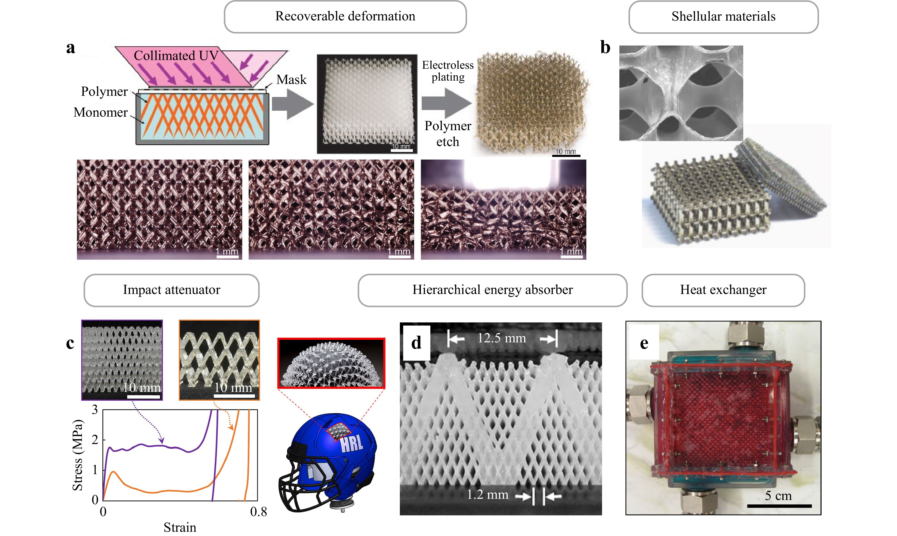
Fig. 7 a Hollow metallic microlattice demonstrating its ultralow density and excellent recoverability110. b Polymeric template and fabricated shellular architecture111. c Elastomeric microlattice impact attenuators. The microlattice material with ordered architectures has been formed from elastomeric photopolymer via SPPW and can absorb impact energy by a combination of controlled bucking, viscous dissipation, and efficient densification112. d Hierarchical polymer microlattice113. e 3D bicontinuous fluid networks for heat and mass exchanger114.
Besides hollow microlattices or shellular materials, the impressive mechanical properties of SPPW-printed polymer microlattices make them desirable for acoustic, vibration, or shock energy absorption112, 113. For example, Clough et al. developed elastomeric microlattice impact attenuators (Fig. 7c) for mitigating damage or injury112. The architected impact attenuators, fabricated from mixtures of thiol-ene and urethane acrylate monomers via the SPPW method, exhibited improved energy absorption compared to state-of-the-art foams for both single-hit and multiple-hit applications. Clough et al. showed that shock-absorbing pads made from microlattice structures had up to 27% higher energy absorption efficiency than the current best-performing expanded polystyrene foam for single impacts, and up to 35% higher energy absorption efficiency than common vinyl nitrile foam for multi-impact. This elastomeric microlattice impact attenuator has the potential to replace existing foams in helmet padding, protective packaging, shock isolators for electronics, and vehicle interiors. Doty et al. also described the use of hierarchical microlattice structures for tunable mechanical properties and energy absorption113. They expanded the SPPW process to create hierarchical architected materials resulting from the superposition of two constituent microlattice structures. The hierarchical structures consist of a small-scale microlattice interpenetrating within a larger microlattice (Fig. 7d). Compression testing showed that the absorbed energy of the hierarchical structures was equal to or synergistically greater than the sum of the absorbed energy by the small and large-scale lattice structures, obtained separately. Furthermore, Roper et al. presented 3D bicontinuous fluid networks with thin-walled interfaces, enabling a polymer heat exchanger (Fig. 7e)114. These bicontinuous fluid networks were implemented by the fabrication of sacrificial polymeric scaffolds through SPPW, conformal coating with parylene, and then selective removal of the sacrificial scaffold. As mentioned above, self-propagation with the conformal coating method enabled the fabrication of hollow microlattice networks. This approach enabled the use of a wide variety of interfacial materials, including metals, ceramics, and polymers, which were selected for multifunctional properties such as electrical conductivity, antifouling ability, and low density114. The bicontinuous fluid networks fabricated by SPPW can open new avenues for biological heat and mass exchange systems toward artificial organs, including artificial lungs, with similar dimensions to biological organs. The key unmet need in creating multi-scale metamaterials spanning the nano-, micro-, and meso-scales is devising manufacturing methods with sufficient scalability to print structures in a bulk deposition manner with nanoscale precision.
-
New types of light-collecting or light-guiding architectures can be fabricated through SPPW to potentially increase and concentrate the delivery of optical energy, which can be leveraged to increase energy conversion in solar cells115, 116. Biria et al. demonstrated a silicon solar cell encapsulant embedded with light-guiding architectures fabricated via SPPW method (Fig. 8a). This provided a proof-of-concept demonstration of the synthesis and deployment of the periodical optical waveguide arrays for solar energy collection and suggested a new approach for achieving wide-angle solar energy conversion. The polymer encapsulated with light-guiding waveguide arrays exhibited an increase in the external quantum efficiency (EQE) over a large range of incident angles, indicating enhanced wide-angle collection, which is critical to collecting sunlight over a day or across seasons115. Chen et al. also introduced microfiber optic array structures as top coatings for a front contact silicon solar cell to mitigate shading loss (Fig. 8b). The microfiber arrays were fabricated via SPPW through a photocrosslinking acrylate system using microscale optical beam arrays116. By utilizing a microfiber array, Chen et al. achieved significantly larger refractive index differences between the fibers and the surrounding air, thus widening the angular acceptance ranges and mitigating shading loss. The use of microfiber optic arrays to collect and transmit optical energy led to enhanced EQE (1.61%) and short-circuit current density (up to 1.13 mA/cm2).
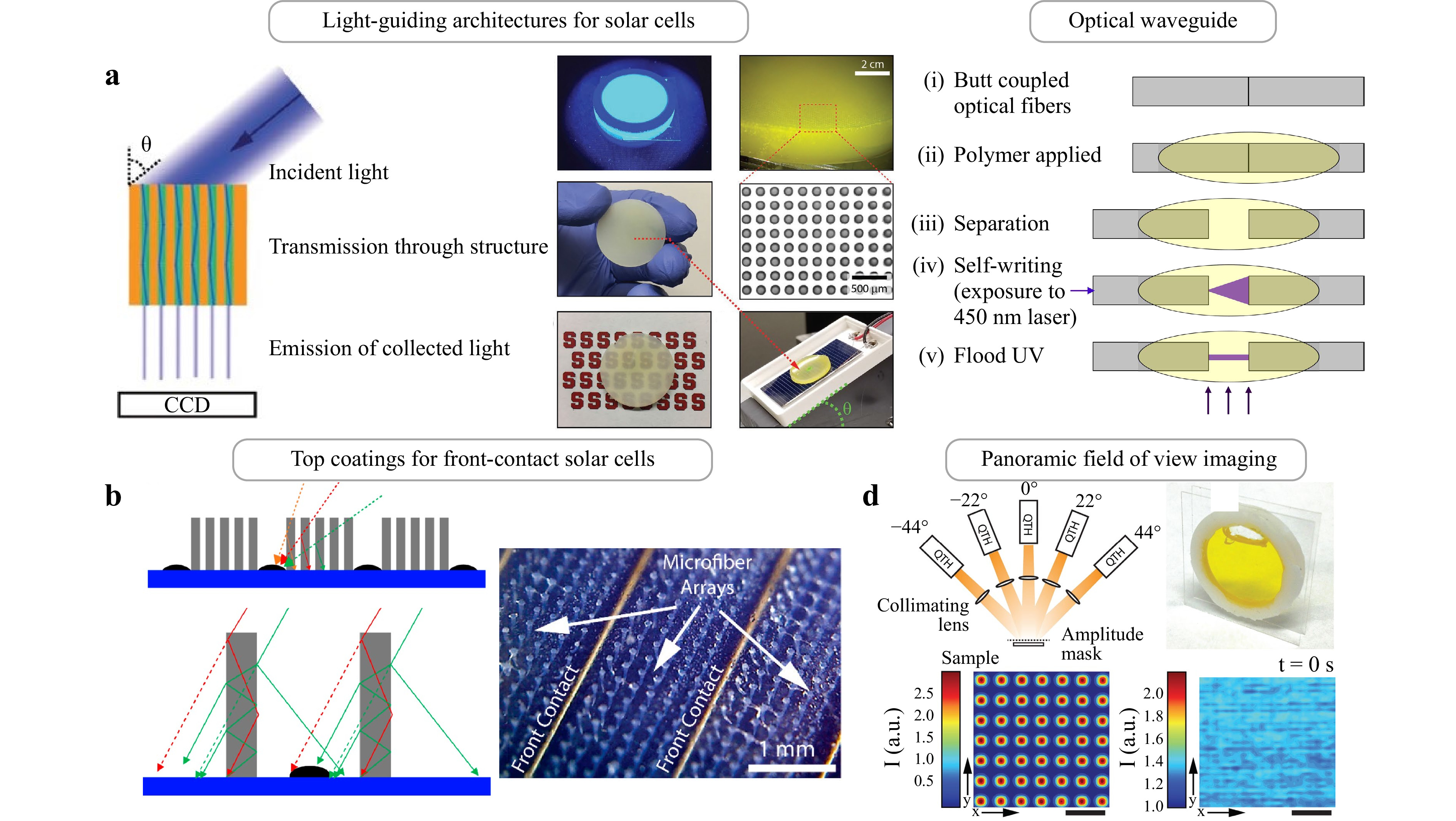
Fig. 8 a Schematic of the solar cell encapsulation architecture with light-guiding arrays115. Photograph of fabricated light-guiding array encapsulates and the setup for EQE measurements including of the waveguide array overlaying a primed silicon solar cell. b Schematic of proposed solar cell architecture consisting of microfiber arrays on the solar cell surface116. c Schematic of fabrication of low-loss optical waveguide structures via SPPW117. d Fabrication of waveguide encoded lattices for panoramic FOV118.
Integrated polymer microstructures can be implemented in various optical and biological applications, including chip-to-chip connections117, imaging devices118, artificial compound eyes119, 3D intestinal tissue models120, or artificial axons. While complex polymeric microstructures for photonic and biological applications still require complex and expensive process technologies such as silicon-based fabrication technology, SPPW can offer advantages especially in terms of low-cost and facile production techniques, as was outlined in Table 1. For example, Günther et al. demonstrated the integration of polymer optics into the end of glass optical fibers for low-loss optical coupling structures, which would be relevant for applications in fields as diverse as information and communication technologies, integrated circuits, and sensor networks117. For the fabrication of optical interconnects, SPPWs provide an attractive solution due to their low cost and low losses. Günther et al. developed an SPPW-based interconnect fabrication process as shown in Fig. 8c. After aligning fibers with 5-axis precision stages, a photocrosslinkable polymer was deposited in the gap between both waveguides, following which the fibers were separated. A light source was connected to the launching fiber, causing the polymerization of the monomer to propagate from the facet of the launching fiber to the receiving fiber due to a self-focusing effect. This resulted in a solid core material surrounded by a liquid cladding, the latter of which was lastly cured through a flood exposure at a different wavelength of a light source. The propagation loss of the SPPW-printed optical interconnect was determined to be 0.8 dB/cm. These integrated polymer optics enable the efficient coupling of light entering and exiting the waveguides, thereby opening the door toward broad applications such as repairing defective optical connections in sensor or communication networks Moreover, Hosein et al. proposed a conceptual imaging device of optical waveguide structures with a panoramic field-of-view (FOV) through the SPPW technique118. Compared with a single-aperture optical system, a compound eye-based optical system possesses large FOV because its multiple waveguides combine and integrate the captured sub-images collected from each individual waveguide (Fig. 8d) Hosein et al. fabricated the waveguide-encoded lattice through microscopic self-trapped optical beams in a photopolymerizable epoxide medium. They measured the angular range to quantify FOV and confirmed that these optical waveguides exhibited an enhanced FOV of 66% compared to a sample without waveguides.
-
SPPW can also be employed to generate micro-patterned surfaces for anti-wetting applications79, 83. Biria et al. proposed a synthesis of hierarchical pore surfaces via the combination of PIPS and light self-focusing in a photopolymer-solvent mixture as shown in Fig. 9a79. A uniform and visible light source were exposed with a photomask consisting of absorbing (bright) and non-absorbing (dark) areas to generate a periodic array of dark regions in the transmitted intensity profiles. Because self-focusing maintains the patterned bright and dark regions in a light profile over the depth of the mixture, the phase separation occurred with the solvent separating into the dark regions. Micro pores on the material surface were achieved after solvent removal with an arrangement of pores spatially corresponding to the photomask pattern. The microporous structures were then spray-coated with polytetrafluoroethylene (PTFE) nanoparticles to render the surfaces superhydrophobic for anti-wetting applications. The PTFE-coated microporous surfaces exhibited large static water contact angles of above 150° indicating superhydrophobicity (Fig. 9a). Different from micropore structures, Li et al. fabricated tunable micropillar arrays using SPPW to achieve functional surfaces and anti-wetting applications83. A periodic array of optical beams was generated through the photomask consisting of holes with blue visible light irradiation. The transmitted light from hole arrays was self-focused onto the end of cured polymer and sustained its own growth like a small fiber-optic into the photocurable photopolymer medium, forming micropillar arrays (Fig. 9b). Then, PTFE nanoparticles were spray-coated onto the micropillar array to obtain superhydrophobic surfaces with water contact angle of above 150° and small slide-off angles (Fig. 9b). This SPPW technique has the potential to be a scalable, facile, yet low-cost approach to precisely control microtextured surface structures to yield surface functionality.
-
Microfabricated polymer-based tissue and organ models have revolutionized the fields of drug discovery and regenerative medicine. Most of the polymer-based microtissues and organ constructs aim to reproduce the morphology and often mechanical properties of biological tissues or organs in vitro. These biomimetic microstructures rely on relatively complex fabrication techniques, including moldless 3D bioprinting approaches, which enable fabrication of complex multicellular geometries of organs and tissues including microvasculature. However, traditional extrusion and DLP-based 3D-printing techniques become increasingly challenging with demands on decreasing feature size (< 50 μm) and low material Young’s moduli (< 1000 kPa). In particular, hydrogels, which are often used to mimic soft tissues such as skin, intestine, brain, or mucus, are challenging for 3D microfabrication of complex geometries with high aspect-ratios and curvatures. The SPPW technique with photopolymerizable hydrogels can mitigate these restrictions. For example, Castaño et al. reported that SPPW could be used to fabricate morphologically complex tissue models such as the intestine through self-propagation of 3D villi-like microstructures using poly(ethylene glycol) (PEG)-based hydrogels (Fig. 10a)121. The hydrogel micro-scaffolds were easily integrated with a standard characterization technique such as a commercial Transwell® system to support the growth of epithelial cells and to evaluate the barrier properties of the biomimetic intestinal epithelium formed.
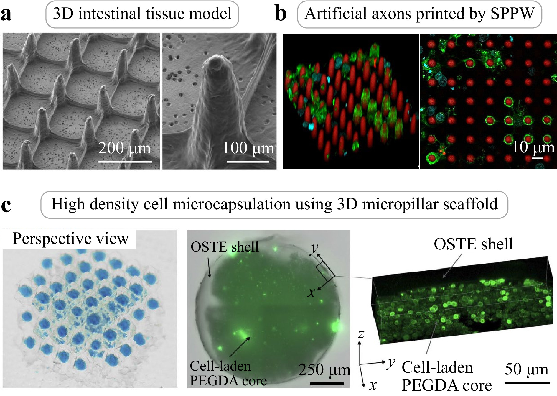
Fig. 10 a 3D intestinal villi-like microstructures fabricated by SPPW on poly(ethylene glycol) hydrogels (Left: Scale bar = 200 μm. Right: Scale bar = 100 μm)121. b Artificial axons printed through (DLP-based) SPPW printing13. c 3D fluidic particle arrays inside polymer micropillar scaffolds (Left) and bright field images (Middle) and confocal images (Left) of a core-shell microcapsule that contains yeast cells123.
SPPW applications extend to the central nervous system (CNS), involving biomimicry of cells within brain tissue. Espinosa-Hoyos al. recently demonstrated generation of an engineered artificial axon, mimics of biological neuronal axons fabricated through DLP-based 3D printing, direct ink writing, and more recently, hybrid SPPW methods using digital and physical photomasks122. As shown in Fig. 10b, these artificial axons were of uniform ~10 μm diameter, ~50 μm height and ~100 kPa in stiffness. Furthermore, the artificial axons were compatible with culture of oligodendrocytes, which adhered to and ensheathed the printed axons with myelin membrane, mimicking the biological process of myelination in the CNS. Creating 3D cylindrical structures with low stiffness, high aspect-ratio, and uniform small diameter (≤ 10 μm) was essential to correctly mimic the structure of biological axons. To achieve this, Espinosa et al. developed compliant, biocompatible hydrogel polymers and specialized additive manufacturing techniques to create artificial axons inspired by the physical and mechanical properties of neuronal axons in the human brain. It is noteworthy that computational modeling of the unique viscoelastic mechanical characteristics of hydrogels remains an open challenge yet to be addressed in the context of SPPW applications.
Another promising application of SPPW-printed microstructures is the field of microfluidic generation and droplet manipulation, which may be useful for medical diagnostic assays, biosensing surfaces, and cell culture123, 124. Hansson et al. demonstrated a platform for the fabrication of synthetic microfluidic paper with well-controlled arrays of interlocked micropillars, formed by SPPW through a photomask124. Interconnected micropillars provide high surface area and porosity, as well as high capillary collapse resistance (i.e., resistance to capillary collapse during manufacturing and operating). Moreover, the platform exhibits a wide range of capillary pumping speeds, high optical transparency, and low device-to-device variation. These results illustrate the potential of synthetic microfluidic structures as high area/volume biosensing surfaces, providing improved performance compared to conventional porous microfluidic materials. Yasuga and colleagues reported emergent 3D fluid lattices by the occurrence of fluid trap geometries in every lattice unit cell of SPPW-printed interconnected solid scaffolds, which can be used for self-digitization, generation, transport, and merging of microdroplets inside 3D architectures123. A 3D solid scaffold produced using SPPW was filled with two immiscible fluids, which spontaneously self-organized as discrete fluidic particles (in blue) in a continuous phase to yield a 3D tri-material periodic structure (Fig. 10c, left). One of biological applications of this 3D fluid lattice is the fabrication of a high-density cell microencapsulation architecture (Fig. 10c, middle and right). As a conceptual demonstration, Yasuga et al. created microcapsules containing a high density of living biological cells, with ten million cells per milliliter, which is approximately an order of magnitude higher than the density achievable using alternative technologies. Due to their easy removal from the 3D scaffold, these cell-laden microcapsules could be available for cell-based drug delivery or in vivo implantation.
-
Apart from structural resolution and complexity (i.e., minimum controllable feature size), the scalable and high-throughput fabrication of high aspect-ratio biological constructs is largely determined by the materials used and the fabrication methodology. Conventional 3D-printed high aspect-ratio structures can be difficult to inexpensively manufacture on a large scale, which limits their practical utility. In contrast, the SPPW process may allow for easier scale-up and commercialization of high aspect-ratio biological constructs. For example, to improve the fabrication throughput of artificial axons while maintaining overall quality and resolution, we demonstrated a one-step printing of high aspect-ratio structures of biocompatible and compliant hydrogels using digital and physical photomasks (Fig. 11a, b)122. As shown in Fig. 11a, high aspect-ratio (up to 1:75) pillars could be achieved with a single exposure using a digital photomasking in the DLP-based system. The fabricated pillars were highly reproducible, with tunable Young’s moduli spanning approximately 0.1-140 kPa. Furthermore, the large-area fabrication of uniform vertical artificial axons was recently demonstrated via the SPPW process by transmitting a light source through a cost-effective physical photomask (Fig. 11b). Fabricated pillars of diameter 3.5-8.0 μm and height 40 μm were produced with a single exposure using a UV light source. This demonstrates a significant increase in throughput, circumventing the additional time cost associated with horizontal translation in conventional DLP systems. We also anticipate that this method may be compatible with the in-well fabrication of artificial axons in multiwell plates. Along the lines of in-well fabrication, Hwang and colleagues demonstrated an advanced 3D bioprinting method that enables the direct production of complex 3D tissue scaffolds within conventional multiwell cell culture plates for high throughput preclinical drug screening and disease modeling (Fig. 11c)125. Direct manufacturing of 3D biological constructs inside conventional analysis platforms (e.g., multiwell plates and T-flask) could avoid the high contamination risk and the need to transfer fragile biological constructs. Furthermore, due to the high compatibility with light-based printing methods, SPPW shows promise for enabling the scalable and high-throughput production of high aspect-ratio biological constructs. Recently, Kim et al. proposed a scalable light-based microprinting method by harnessing multiple tiny lenses resembling an insect compound eye126. Despite intense ongoing research activity, most DLP-based 3D printing relies on a single-aperture imaging system in which an incoming image is projected as only one output. Consequently, the maximum capacity of transferred image information is fundamentally limited by this single-aperture imaging platform, resulting in a tradeoff between minimum feature size and maximum area in one printing process. To address this tradeoff, they demonstrated an integral imaging technique that the planar microlens array combined with the DLP printing process allows for scalable additive manufacturing via the massive replication of their original image and integration of multiple incoming images, producing periodic microstructures spanning four orders of magnitude from the micrometer scale to centimeter-scale (Fig. 11d). We expect that this imaging strategy may incorporate with the SPPW process to produce parallel high aspect-ratio 3D microstructures over a large area at the same time. Although further developments are essential, the printing result of the suspended fiber arrays with feature sizes of 5~10 μm up to an exposure area of 2500 mm2 in Fig. 11d supports the potentials of high-throughput 3D microprinting for multiple biological construct samples over macro-scale dimensions.
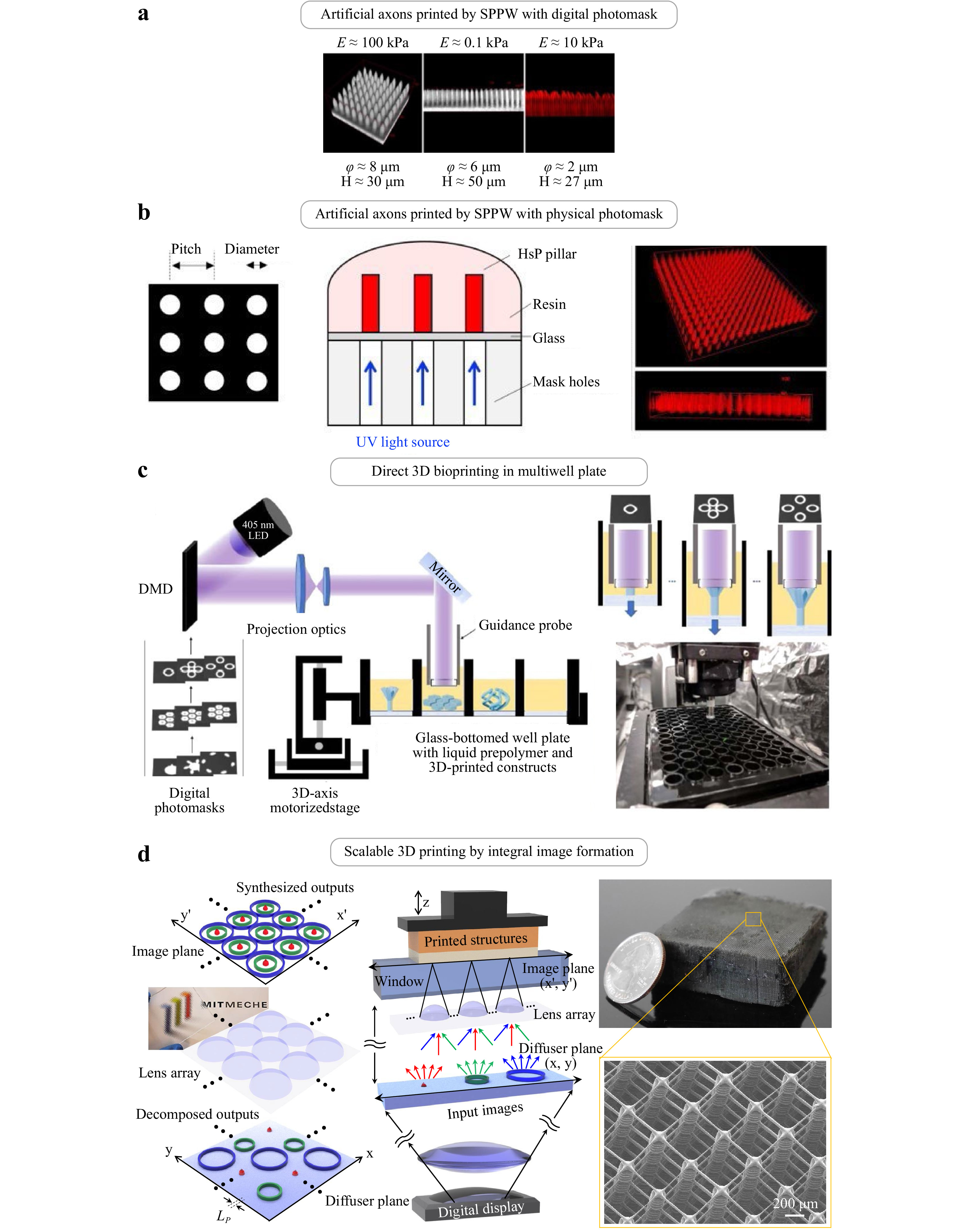
Fig. 11 a, b One-step artificial axon fabrication through hybrid SPPW using digital and physical photomasks122; a Artificial axons fabricated by self-propagated photopolymerization, facilitated by digital mask projection. Estimated range of Young’s elastic modulus E span four orders of magnitude (0.1 – 100 kPa). Increasing aspect-ratio from left to right. b One-step artificial axon fabrication through SPPW using physical photomasks122. Glass slides covered with biocompatible photopolymer resin were placed directly on top of quartz/chrome photomasks consisting of circular holes with predetermined diameter and pitch. c Direct 3D bioprinting in multiwell plate125. Based on conventional DLP-based 3D printing, a digital projection was synchronized with a controlled 3-axis motorized stage with a well plate holder, enabling in-well fabrication of biological 3D constructs. In particular, the reflected light pattern was projected via a hollow guidance probe terminated with an optically transparent glass window with PDMS coating to prevent unwanted adhesion during photopolymerization. d Scalable 3D microprinting by integral imaging technique126. The parallel and reconstructed imaging patterns were projected by the microlens array combined with digital microdisplay. The cubic-truss polymeric lattice was composed of with strut suspended beam diameter of ~ 5 μm, which can be utilized in customized 3D scaffolds, such as to mimic artificial axons.
-
Photopolymerization allows relatively facile deposition of compliant polymers onto substrates, but new ways to combine this phenomenon with the light-based maskless and digitized mask photolithography can enable fabrication of much more diverse and complex three-dimensional structures. Separately but with clear synergies, the phenomenon of self-propagating polymer waveguides that can enable production of compliant polymers (<100 kPa) in arrays of precisely spaced pillars at aspect-ratios exceeding 10. Coupled with advanced and more complete sets of computational models, seminal conquerable leaps remain to be made in exceeding the capabilities of current SPPW-relevant technologies. While much of the SPPW modeling progress to date has been empirical in development of both the polymers and the printing technologies, multiphysics models are under development with opportunity to validate complex couplings among light interactions and polymerization kinetics. Several classes of applications can benefit by leveraging even basic understanding of SPPW to create structures with increasingly high precision and throughput, ranging from printing of elastomers to hydrogel composites. With strengthened connections among these research communities and topics of polymerization kinetics, optics, and additive manufacturing, we can address current knowledge gaps and enable the translation of such foundational technology into beneficial applications, and anticipate rapid advances in the design and wider use of such (literally) flexible arrays.
-
M.Y. acknowledges the Angela Leong Fellowship Fund 2021-2022 from the Massachusetts Institute of Technology. K.K. acknowledges the financial support of the Natural Sciences and Engineering Research Council of Canada (award no. PDF - 529703 – 2019). S.K. acknowledges the National Research Foundation of Korea (NRF) grant funded by the Korean government (MSIT) (No. 2019R1A5A8083201 and 2022R1C1C1003966). M.Y., A.J., and K.J.V.V. acknowledge the U.S. Department of Defense Congressionally Directed Medical Research Program, and the Deshpande Innovation Center at the Massachusetts Institute of Technology. K.J.V.V. gratefully acknowledges the Michael (1949) and Sonja Koerner Professorship.
Additive manufacturing of high aspect-ratio structures with self-focusing photopolymerization
-
Mingyu Yang1, ,
 ,
, -
Kavin Kowsari2, 3, ,
,
- Nia O. Myrie4, 5, ,
- Daniela Espinosa-Hoyos6, ,
- Anna Jagielska7, ,
-
Seok Kim2, 8, ,
,
-
Nicholas X. Fang2, ,
,
-
Krystyn J. Van Vliet4, 7, ,
- Light: Advanced Manufacturing 3, Article number: 32 (2022)
- Received: 11 December 2021
- Revised: 05 April 2022
- Accepted: 25 April 2022 Published online: 25 August 2022
doi: https://doi.org/10.37188/lam.2022.032
Abstract: Photocrosslinkable polymers have been exploited to attain impressive advantages in printing freestanding, micrometer-scale, mechanically compliant features. However, a more integrated understanding of both the polymer photochemistry and the microfabrication processes could enable new strategic design avenues, unlocking far-reaching applications of the light-based modality of additive manufacturing. One promising approach for achieving high-aspect-ratio structures is to leverage the phenomenon of light self-trapping during the photopolymerization process. In this review, we discuss the design of materials that facilitate this optical behavior, the computational modeling and practical processing considerations to achieve high aspect-ratio structures, and the range of applications that can benefit from architectures fabricated using light self-trapping—especially those demanding free-standing structures and materials of stiffnesses relevant in biological applications. Coupled interactions exist among material attributes, including polymer composition, and processing parameters such as light intensity. We identify strong opportunities for predictive design of both the material and the process. Overall, this perspective describes the wide range of existing polymers and additive manufacturing approaches, and highlights various future directions to enable constructs with new complexities and functionalities through the development of next-generation photocrosslinkable materials and micromanufacturing methods.
Research Summary
Additive manufacturing of high aspect-ratio structures with self-focusing photopolymerization
Photocrosslinkable polymers have been exploited to attain impressive advantages in printing freestanding, micrometer-scale, mechanically compliant features. However, more integrated understanding of both the polymer chemistry and the fabrication processes could enable new strategic design avenues, unlocking far-reaching applications of the light-based modality of additive manufacturing. One promising approach for achieving high-aspect-ratio structures is to leverage the phenomenon of light self-trapping during the photopolymerization process. In this review, we discuss the design of materials that facilitate this optical behavior, the computational modeling and practical processing considerations to achieve high aspect-ratio structures, and the range of applications that can benefit from architectures fabricated using light self-trapping—especially those demanding free-standing structures and materials of stiffnesses relevant in biological applications.


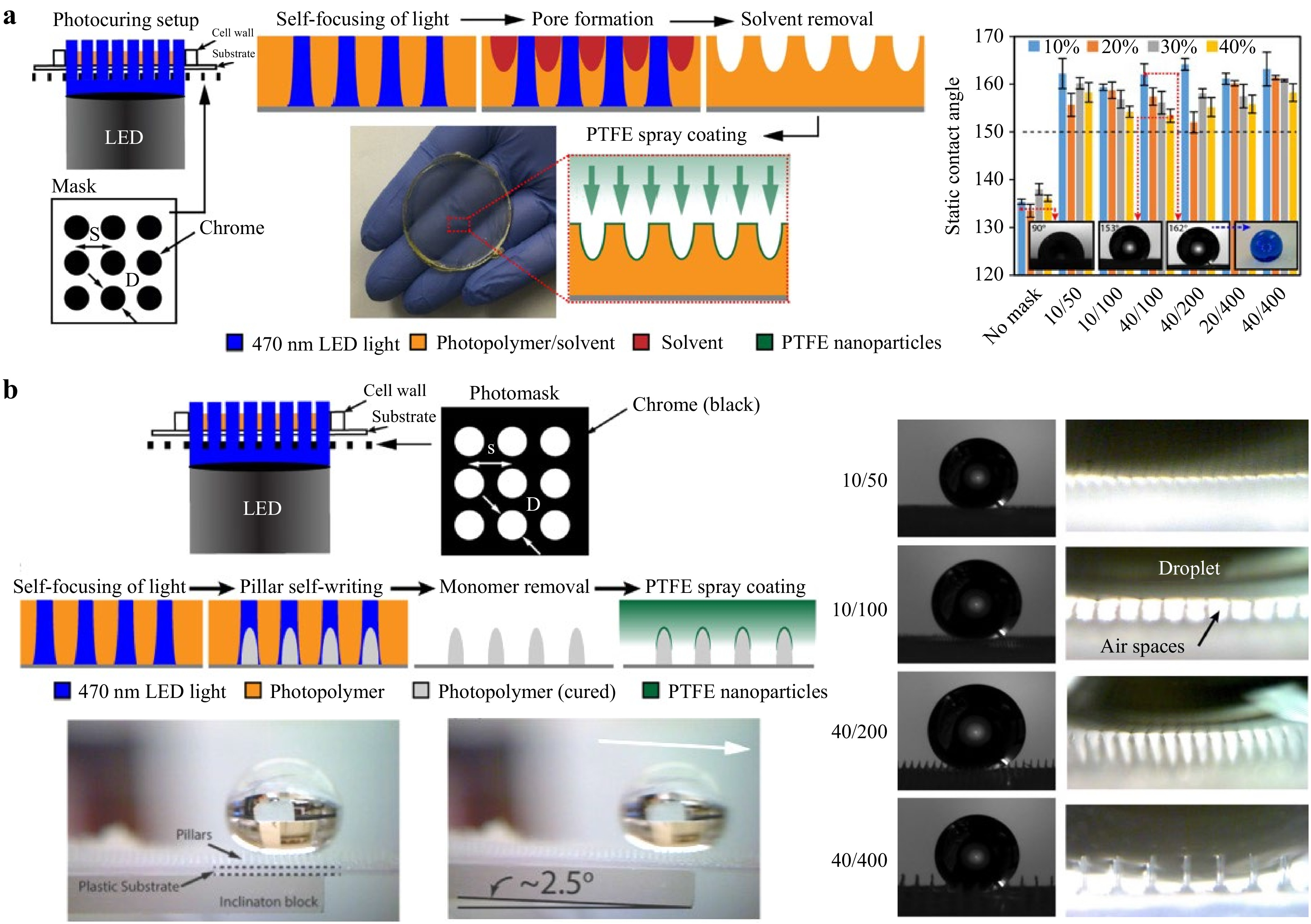
Rights and permissions
Open Access This article is licensed under a Creative Commons Attribution 4.0 International License, which permits use, sharing, adaptation, distribution and reproduction in any medium or format, as long as you give appropriate credit to the original author(s) and the source, provide a link to the Creative Commons license, and indicate if changes were made. The images or other third party material in this article are included in the article′s Creative Commons license, unless indicated otherwise in a credit line to the material. If material is not included in the article′s Creative Commons license and your intended use is not permitted by statutory regulation or exceeds the permitted use, you will need to obtain permission directly from the copyright holder. To view a copy of this license, visit http://creativecommons.org/licenses/by/4.0/.

 DownLoad: