


-
Augmented reality (AR) and virtual reality (VR) are emerging fields in both academia and industry. Virtual images are presented in an immersive and interactive manner, thereby providing a new user experience for various applications. The main platform device for AR and VR is the near-eye display (NED)1, 2. NEDs are glass- or goggle-type wearable display devices. They present virtual digital images that fill the entire visual field of a user or exist in combination with the see-through view of a real scene, enabling VR and AR experiences.
NEDs are composed of a micro-display panel and imaging optics. Light from the micro-display panel, which is placed close to the eye, is collimated by the imaging optics, thereby forming a virtual image at a far distance where the eye can focus comfortably. In AR NEDs, an additional component; that is, an optical combiner, is used to superimpose the virtual images of the micro-display panel onto the see-through light from a real scene in front of the user. As display devices, NEDs have traditional performance metrics, such as resolution and luminance. However, as wearable devices that are close to the eye, NEDs also need to have a compact form factor, light weight, wide field of view (FoV), and large eyebox. Moreover, optical matching of the displayed virtual images to real objects with natural focus cues is important for natural interaction between the virtual images and user. Various optics have been developed to implement AR/VR NEDs2 to satisfy these requirements. However, bulk lenses and mirrors, which are typically used in NED optics, impose limitations on the achievable weight and form factor, making it difficult to realize wearable and aesthetically plausible devices comfortably. The simple two-dimensional (2D) image presentation of each micro-display panel also fixes the virtual image plane to a single distance, thereby hindering the exact optical matching of the virtual images onto the real scene and causing an uncomfortable viewing experience owing to limited monocular focus cues3-6.
In recent years, the application of holographic techniques to AR/VR NEDs has attracted significant attention. Holography records and reconstructs the wavefront of a desired light. As static optical components, holographic devices can replace the bulk optics of conventional NEDs7, 8. Thin and light film-shaped holographic devices contribute significantly to reducing the overall system form factor of NEDs. The high angular and wavelength selectivity of the holographic optical components enables the selective application of different optical powers to spatially overlaid light, thereby realizing optical see-through capability for AR and a single component that is multiplexed with multiple optical functions.
As a dynamic device, the holographic display module can replace the 2D micro-display panel of conventional NEDs9. The holographic display module presents holographic three-dimensional (3D) images to each eye of the user. Full monocular focus cues that are provided by holographic 3D images realize the exact optical matching of the displayed images onto real objects and a comfortable viewing experience, without vergence-accommodation conflict (VAC)3-6, 9. The wavefront reconstruction capability of holographic displays can be used to compensate for the aberrations of NED optics, thereby reducing the required number of optical components in the NED10-12. This feature can also compensate for eye aberrations, and thus, it can enable vision-correcting displays that present clear images without additional vision-correcting lenses13.
In this article, we provide a brief overview of the holographic techniques that are applied to AR and VR NEDs. We explain the basic principles and features of various holographic applications, such as static holographic optical components and dynamic holographic display devices. Current issues and recent progress are also discussed, thereby providing a comprehensive review of the research prospects of holographic techniques in AR and VR applications.
-
A representative static optical component that uses holographic techniques is the holographic optical element (HOE)7, 8,14-16. HOEs are diffraction gratings that are fabricated using holographic techniques. During the recording process, a reference beam and signal beam are illuminated on the recording medium, and the interference pattern is recorded. As a recording medium, a photopolymer that records the interference pattern as a spatial refractive index modulation is frequently used. In recent years, liquid crystals (LCs) have also been used to record the interference pattern as a form of the spatial distribution of LC director orientations8. Once the pattern has been recorded, the HOE diffracts the incident reference beam, which is usually known as the probe beam in the reconstruction process, to reconstruct the original signal beam. Depending on the signal beam that is used in the recording process, HOEs can offer various optical functions, including diffusers, lenses, and mirrors. The thickness of HOEs is typically less than several tens of micrometers, which enables thin and light form factors of the overall system. However, HOEs are sufficiently thick to exhibit volume hologram characteristics, resulting in high diffraction efficiency and strong angular/wavelength selectivity. These features make HOEs versatile for various AR/VR NEDs.
Fig. 1 depicts typical examples of HOE applications in AR NEDs. In Fig. 1a, the HOE acts as a forward-scattering screen for the projected images17. Owing to the angular and wavelength selectivity, the HOE only scatters the light from the projector, while allowing the light originating from the real scene to pass through unaffected. This selective screening function of the HOE enables on-axis AR NED optics with a simple configuration. Fig. 1b presents an example of an HOE working as an optical combiner18 for a projection-type AR NED. As illustrated in Fig. 1b, the light from the laser projector is collimated and projected onto the HOE that is placed in front of the eye. The HOE acts as a parabolic mirror and focuses the projected light onto a spot on the eye pupil plane so that the image is directly written onto the eye retina plane. Again, the wavelength and angular selectivity of the HOE allow the see-through view of the real scene to be transmitted to the eye unaltered, thereby enabling an optical see-through AR configuration. Fig. 1c depicts another typical application of the HOE; that is, the in- and out-couplers of waveguide-type AR NEDs19. The light from a micro-display panel is coupled to the waveguide by the HOE, which diffracts the incident light at an angle for the total internal reflections inside the waveguide. Subsequently, the out-coupler HOE in front of the eye diffracts the guided light directly towards the eye, thereby presenting virtual images.

In all of the examples in Fig. 1, the angular and wavelength selectivity of the HOEs make them work only for the projected images, remaining transparent to the real scene light. However, the selectivity can be further used to provide different optical functions for the projected light. Fig. 2a, b show examples of the angular selectivity. In Fig. 2a, two HOEs work as scattering screens, but only for light that is projected from the designed directions20. The images from the two projectors are scattered only from the corresponding HOE screens, thereby forming double-layer images. In Fig. 2b, a single HOE is recorded by multiplexing two optical functions; that is, a scattering screen and a micro-mirror array, using two angularly separated reference beams21. The recorded HOE works as a screen for the light from a projector, while it works as a micro-mirror array for the light from another projector, thereby enabling 2D and 3D screens, respectively. Fig. 2c presents another example of HOE selectivity. Unlike photopolymer-based HOEs with spatial refractive index modulation grating, LC-based HOEs have polarization selectivity, exhibiting different optical functions to orthogonal polarizations. The two HOEs in Fig. 2c work as concave mirrors only for left circularly polarized (LCP) light and are transparent for right circularly polarized (RCP) light. The example configuration in Fig. 2c uses this feature to switch the exit pupil of the system by focusing the projected beam with different concave mirror HOEs selectively22.
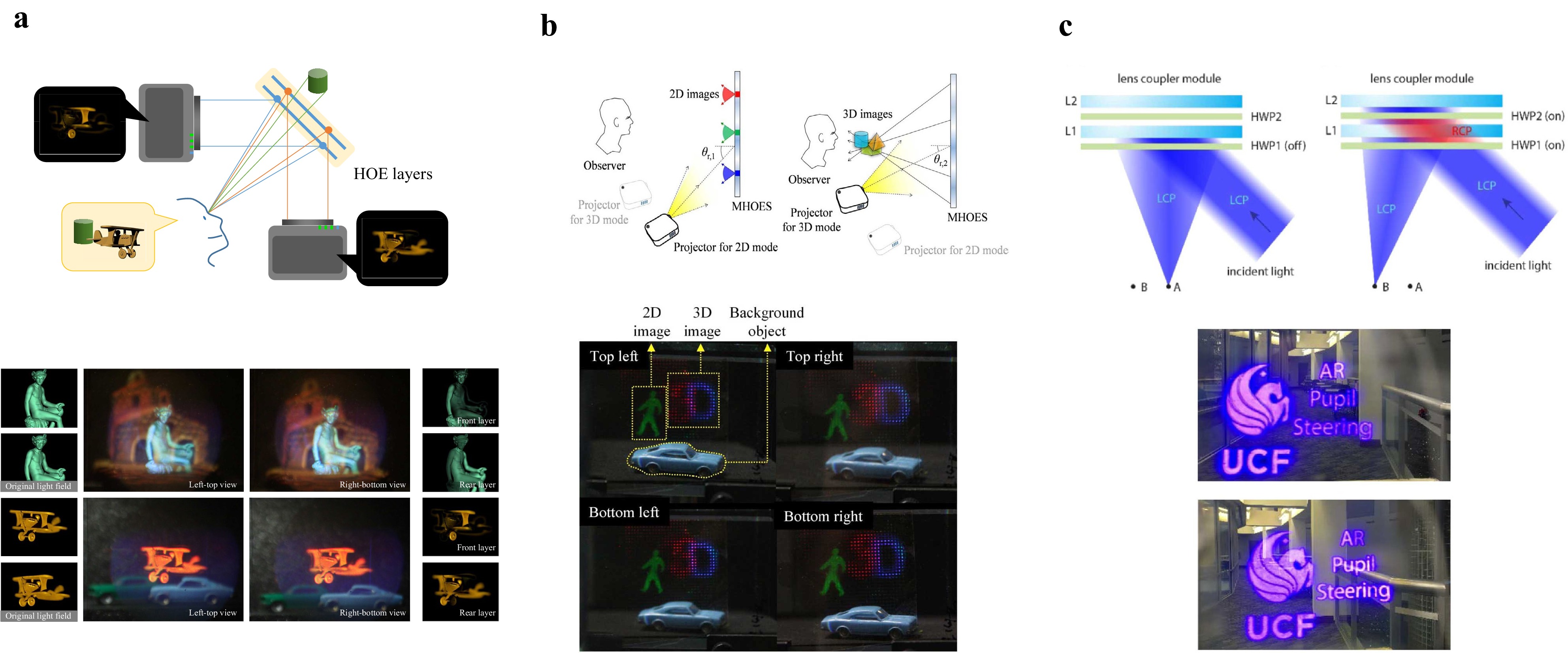
Fig. 2 Selectivity of HOEs: a two HOEs working as screens only for the corresponding projectors using angular selectivity20, b an HOE with dual functions that are multiplexed using angular selectivity21, and c LC-based HOEs with polarization sensitivity22. Images reprinted with the following permissions: a20 from ACM (Association for Computing Machinery); b21, c22 from Optica Publishing Group.
The thin and light form factors, high diffraction efficiency, and strong selectivity of HOEs, as introduced above, have attracted significant attention and have resulted in the application of HOEs to various AR and VR NED research topics. Fig. 3 depicts several examples in which HOEs are used to expand the eyebox23-26, enlarge the FoV27,28, increase the number of image planes29, and implement foveated displays30, 31. Figs. 3a−c show the eyebox expansion of Maxwellian AR NEDs. The Maxwellian AR NED focuses the image beam onto a single spot in the eye pupil plane. Owing to the reduced exit pupil of the system, the displayed images have a large depth of field (DoF), thereby providing always-focused images to the user, regardless of the focal power of the eye lens. A drawback of the Maxwellian display is that the images are visible only when the focal spot falls inside the eye pupil, which limits the effective eyebox of the system. In the technique shown in Fig. 3a, the eyebox limitation is mitigated by using a multiplexed HOE24. The HOE in Fig. 3a functions as multiple concave mirrors, thereby creating multiple focal spots with separation of the average eye pupil size. One of the focal spots falls inside the eye, so that the images are presented in the extended eyebox area. Fig. 3b extends the eyebox using a similar principle, but with LC-based HOEs25. Collimated and linearly polarized light is diffracted along the x-axis by the first HOE and it is separated into three beams; that is, two oppositely diffracted beams with LCP and RCP polarizations, and one non-diffracted DC beam. These beams are converted back into linear polarization by a quarter-wave plate and diffracted again into three directions on the y-axis by the second HOE. Finally, 3 × 3 focal spots are created in the eye pupil plane, resulting in 2D expansion of the eyebox. In Fig. 3c, a polarization grating, multiplexed HOE, and geometric phase lens, which is a type of LC-based HOE, are combined to switch between two sets of interleaved multiple focal spots by controlling the input beam polarization26.
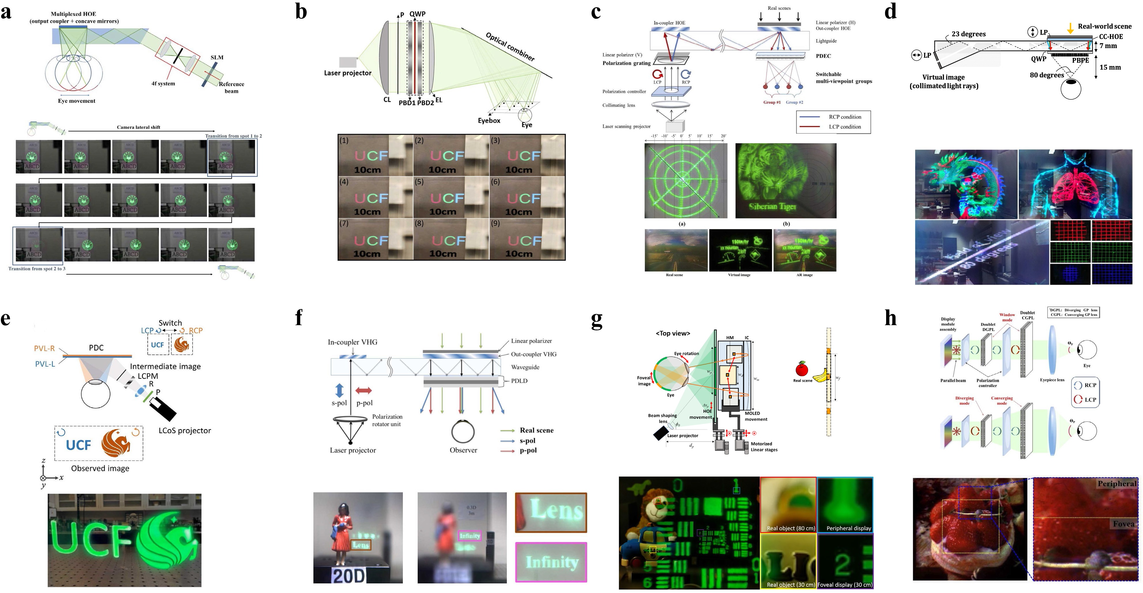
Fig. 3 Recent examples of HOE applications for AR NEDs: a eyebox replication using a multiplexed HOE24, b eyebox replication using polarization-dependent HOEs25, c viewpoint switching using polarization-dependent HOEs26, d FoV enhancement using polarization-dependent transmission-type HOEs27, e FoV enhancement using polarization-dependent reflection-type HOEs28, f dual focal plane formation using polarization-dependent HOEs29, g foveated display using an HOE30, and h foveated display using a polarization-dependent HOE31. Images reprinted with the following permissions: a24,b25, c26, e28, f29, h31 from Optica Publishing Group; d27 (CC BY 4.0); g30 from ACM (Association for Computing Machinery).
Fig. 3d, e depict the FoV expansion of AR NEDs using HOEs. In the technique27 shown in Fig. 3d, an eye-piece element, which is an RCP converter that is sandwiched between a pair of geometric phase lenses, is used. The eye-piece element focuses on the RCP projected images while allowing the LCD real-scene light to pass through unchanged, which enables an AR experience. The chromatic aberration of the geometric phase lenses is pre-compensated by a wavelength-multiplexed out-coupler HOE, which has different focal lengths for the red, green, and blue wavelengths. The dual geometric phase lenses and optical power of the HOE enable a short effective focal length, achieving a large FoV of up to 80°. In the technique28 shown in Fig. 3e, two LC-based HOEs are stacked to diffract the incident RCP and LCP light to different FoV areas selectively, thereby doubling the overall FoV of the system.
Fig. 3f presents an example of an HOE application with dual image planes29. In conventional NEDs, virtual images are formed on an image plane that is fixed at a single distance. The fixed 2D image plane is contrasted by the varying-depth stereoscopic 3D image content, which creates a VAC problem. The VAC problem can be partially mitigated by increasing the number of image planes. In Fig. 3f, the image planes are formed at two distinct distances using a polarization-dependent eye-piece element that is similar to that shown in Fig. 3d. The eye-piece element in Fig. 3f has zero and negative optical powers for the P- and S-polarized light, respectively, thereby forming dual image planes at optical infinity and at a close distance, depending on the input light polarizations.
Finally, the examples in Fig. 3g, h show the implementation of foveated displays using HOEs. In Fig. 3g, the HOE works as an optical combiner, and the peripheral images are presented in the Maxwellian display configuration with a wide FoV30. High-resolution foveal images are presented using a micro-OLED panel. The high selectivity and thin shape of the HOE are effectively used in implementing the wearable foveated AR NED prototype with a compact form factor. In Fig. 3h, the polarization-selective focal length of the LC-based HOE is used to provide different magnifications of the virtual images, thereby realizing a time-multiplexed foveated display using a single display panel31.
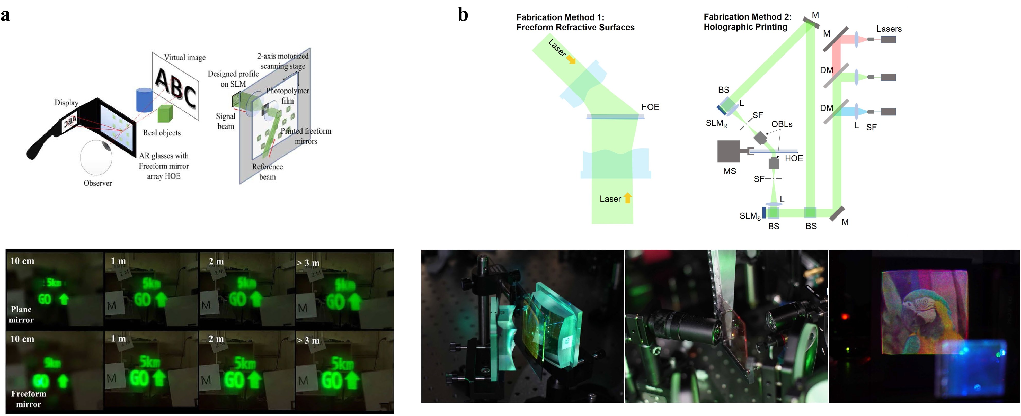
Despite many advantages and possible applications to AR/VR NEDs, HOEs still exhibit issues including material reliability, reduced diffraction efficiency for full color, and aberrations. Aberrations are of particular importance because the incident light is usually highly slanted in NED optics. In holographic NEDs, which will be discussed in a later section, these aberrations can be pre-compensated in the hologram content; that is, by means of a computer-generated hologram (CGH). However, in other types of NEDs, the HOE must be recorded with properly adjusted reference and signal beams to minimize aberrations. In recent years, HOE recording techniques using a holographic printer32, 33 or freeform optics33 have been reported, as illustrated in Fig. 4, which are expected to contribute to the image quality enhancement of AR and VR NEDs using HOEs.
-
A metasurface is a photonic structure with artificial subwavelength scatterers; that is, meta-atoms that are distributed in a 2D plane. The geometry of an individual meta-atom can be designed to control the phase, amplitude, and polarization of the transmitted or reflected light, and thus, it exhibits various optical functions. Full 2π range phase control with a subwavelength thickness structure enables ultra-thin and light optics with a high numerical aperture (NA), which is ideal for AR and VR NEDs. Recent progress in metasurface optics has made the application of metasurface lenses to AR and VR NEDs a viable option, based on which research has been initiated34-36.
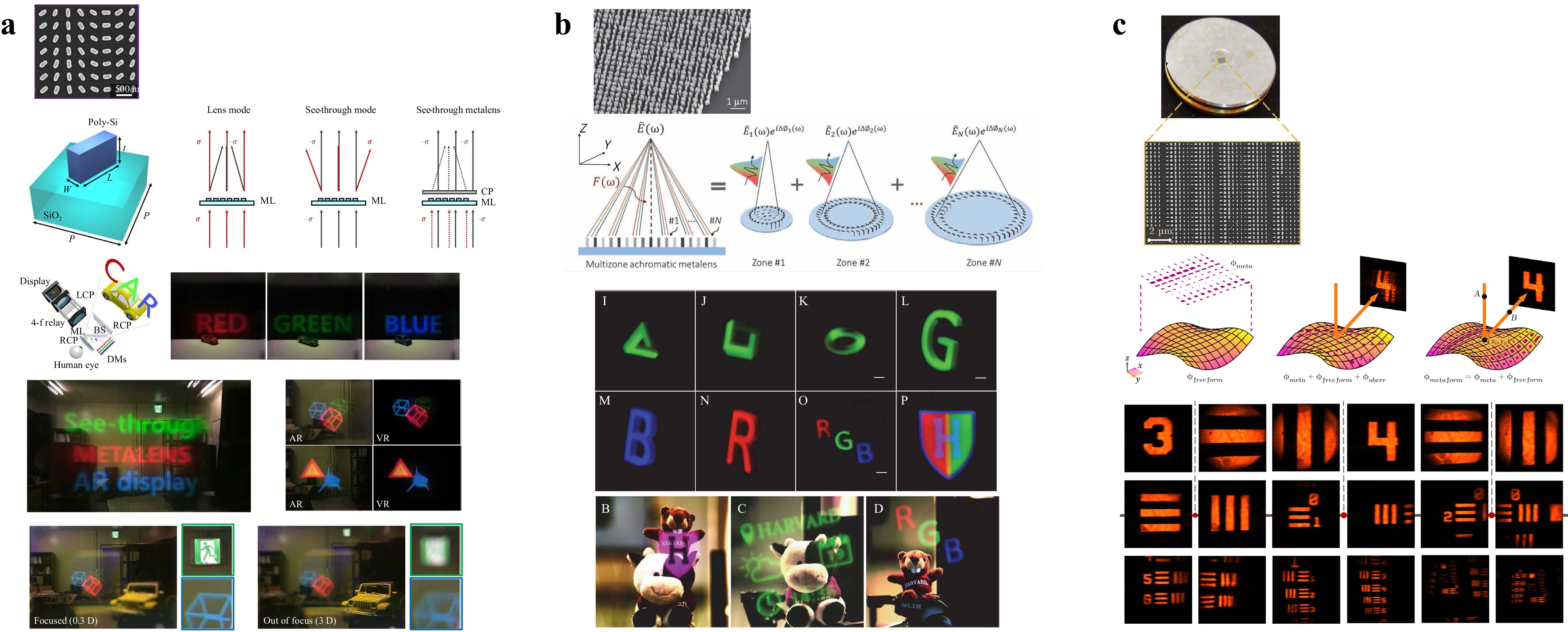
Fig. 5 presents examples of the metasurface lens applied to AR and VR optics. In the work37 depicted in Fig. 5a, a transmission-type metasurface lens made of a 2D array of dielectric nano-rods is used. The width and height of the nano-rods are designed to provide appropriate anisotropy, which determines the transmission efficiency of the co-polarized and cross-polarized light. The orientation angle of the nano-rods is designed to provide a proper phase profile to the cross-polarized light, following the geometric phase or Pancharatnam–Berry (PB) phase principle. Unlike conventional metasurface lenses, the direct transmission of co-polarized light is deliberately maintained to enable a see-through view of the real scene. The fabrication is conducted using a nano-imprinting process with the implementation of a 20 mm diameter metasurface lens. Owing to the high 0.61 NA and transmission-type geometry of the device, the implemented system provides 90° FoV full-color AR images, which demonstrates the potential of metasurface lens application to AR and VR NEDs. In this work, the metasurface lens works in broadband but the chromatic aberration remains, which requires additional optics for compensation. Fig. 5b depicts a work that reported an achromatic metasurface lens for AR and VR applications38. The lens aperture is divided into multiple radial zones as in the conventional Fresnel lens, and meta-atoms are designed for each zone. Unlike conventional Fresnel lenses, in which the dispersion is determined solely by the intrinsic material dispersion, the meta-atoms in each zone are designed to provide an appropriate phase profile, dispersion, and phase discontinuity at the zone boundary, which enables a common focal length at three wavelengths; that is, red, green, and blue. The fabricated device has a 2 mm aperture and 0.7 NA, and was verified with full-color AR and VR NED configurations. Finally, the metasurface lens design and fabrication on a freeform surface39 has recently been reported, as illustrated in Fig. 5c. The overall optical power can be divided and assigned to the freeform surface geometry and metasurface lens with a balance considering the design, fabrication, and tolerance issues. The fabrication of a 2 mm × 1.5 mm metasurface mirror on a toroidal surface has been demonstrated experimentally. Although issues35 remain, including the fabrication of large lenses and high-order aberrations such as coma, the ultra-thin form factor, high NA, and high design flexibility make the metasurface lens attractive in AR and VR applications, and progress in this area is expected to be fast.
-
The micro-display panels of AR and VR NEDs reproduce the spatial amplitude distribution on the panel surface, thereby presenting 2D images. Holographic displays reconstruct the wavefront of the desired 3D images by modulating the amplitude or phase of the light using a spatial light modulator (SLM). Holographic NEDs refer to those that are configured with a holographic display module instead of the usual micro-display panel9.
Fig. 6 depicts the differences between the typical AR/VR NEDs and holographic NEDs. In the typical AR/VR NEDs shown in Fig. 6a, 2D images are displayed on a micro-display panel. Diverging light from each pixel of the micro-display panel is refracted by the optics, forming virtual images on a plane that is conjugate to the display panel. CGHs corresponding to the desired 3D images are loaded onto the SLM in the holographic AR/VR NEDs, as illustrated in Fig. 6b. Coherent light illuminating the SLM is modulated in amplitude or phase by the SLM, which reconstructs the wavefront of the 3D images.

Fig. 6 Comparison between: a conventional stereoscopic NED and b holographic NED.
An apparent advantage of holographic NEDs is the presentation of 3D images. In conventional NEDs, a stereoscopic image pair is presented to the left and right eyes, and the user perceives 3D depth from the binocular parallax in the stereoscopic images, as illustrated in Fig. 7a. However, the optical virtual image that is seen by each eye is still in the 2D plane that is conjugated to the micro-display panel, and the focal power of the eye lens is accommodated to that distance. As the accommodation distance is fixed at the optical conjugate plane, although the perceived distance or convergence distance varies according to the presented stereoscopic image content, a mismatch occurs between the two distances, which is known as VAC. VAC is one of the major causes of dizziness and discomfort in AR and VR experiences3-6. Although VAC is common in many 3D display applications, it is of particular importance in AR and VR applications, as it is severe in the distance range of AR and VR. Fig. 7b depicts the degree of VAC measured in the size of the circle of confusion. When the stereoscopic 3D image distance is larger than the optical virtual image distance of 2 m, the VAC is not significant. However, when the 3D image is closer to the eye, the VAC becomes severe. In AR and VR applications, images that are close to the eye, usually within the arm’s length, are important, because they allow direct interaction with the user. As illustrated in Fig. 7b, the VAC in this distance range is significant and requires appropriate mitigation. Various techniques, including Maxwellian displays40-44, varifocal optics45, multiple image planes46-48, and light field displays49-54, have been developed in this regard. However, holographic displays9,55-58 provide the most complete solution by reconstructing optical 3D images to each eye with a continuous wavefront. Fig. 8a depicts the 3D image presentation of holographic NEDs with an example of an experimental demonstration11. Owing to the optical 3D image formation that is provided by the holographic display, each part of the 3D images is separately focused and blurred according to the camera focus.
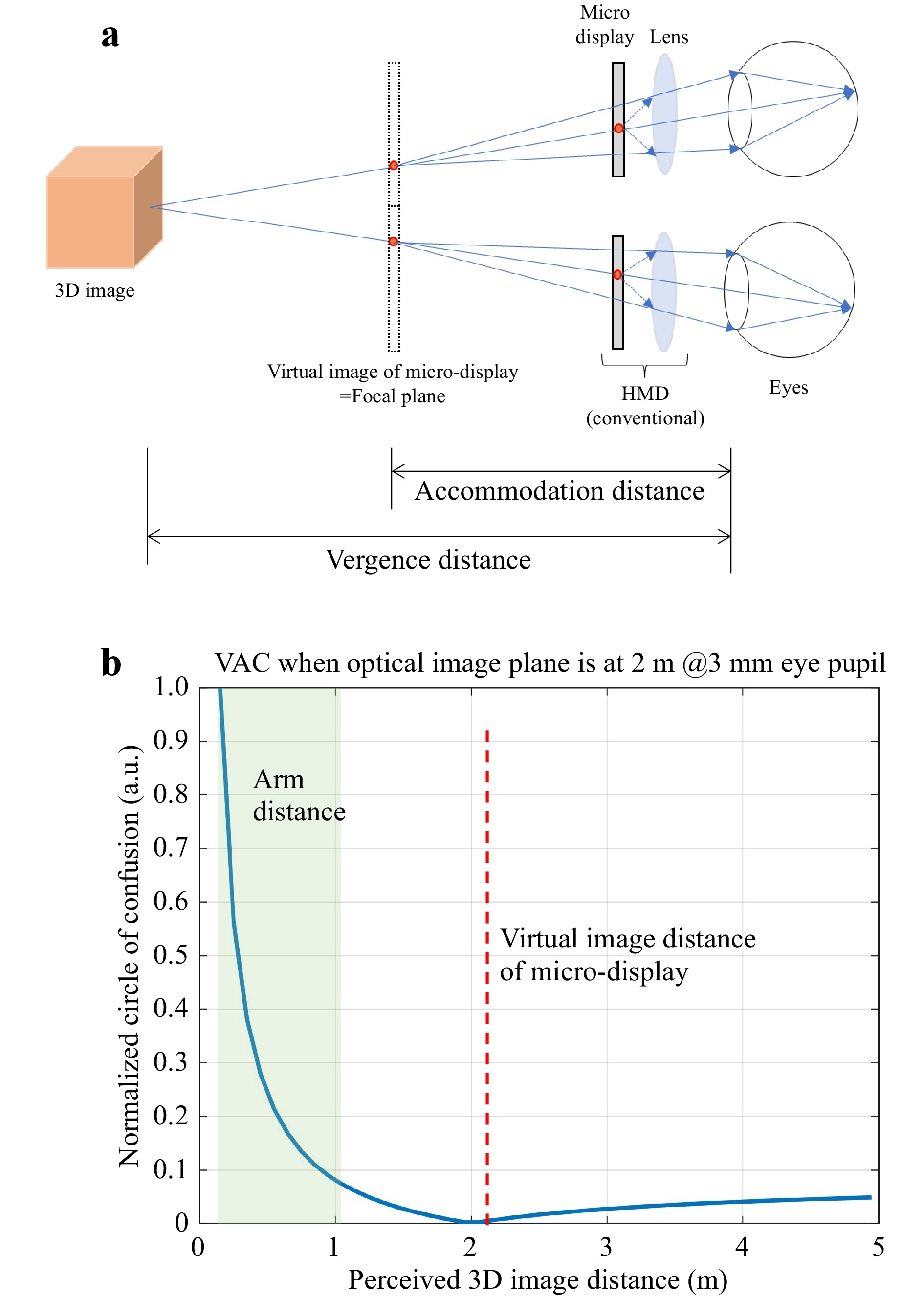
Fig. 7 VAC: a conceptual illustration, b degree of VAC represented in circle of confusion.
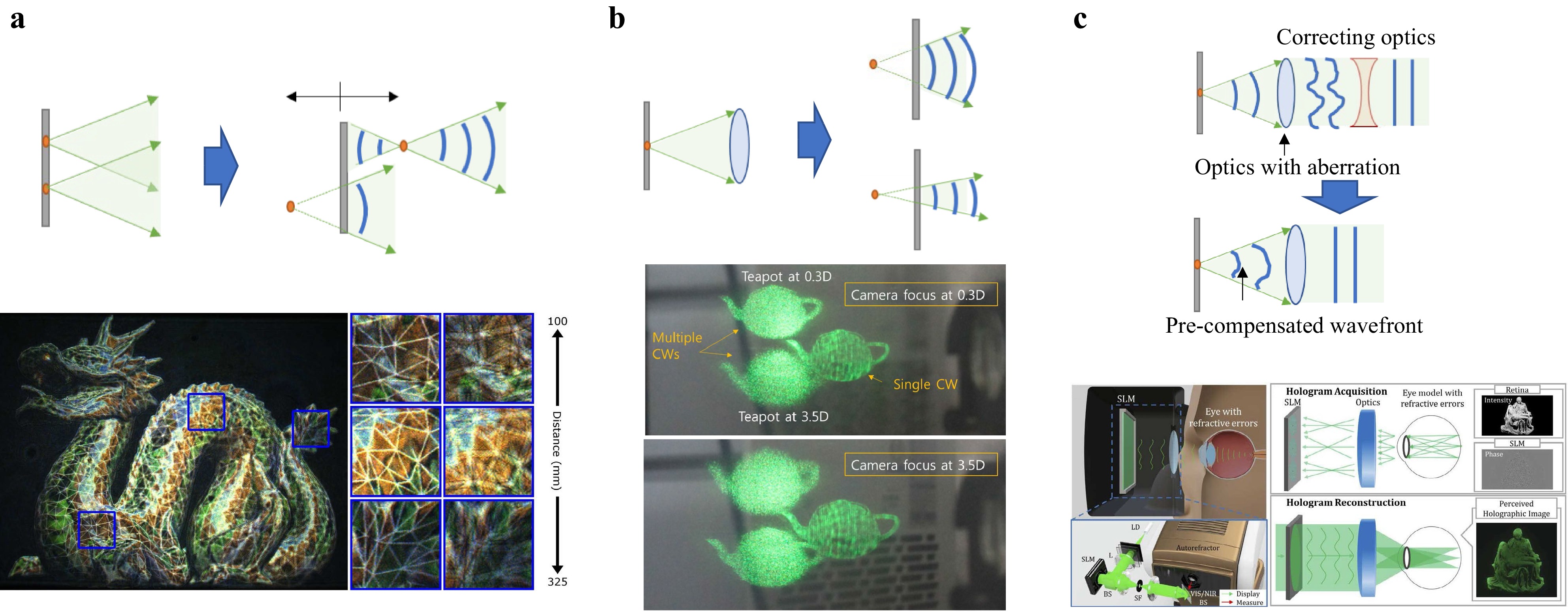
Although 3D image presentation without the VAC problem is a prominent advantage of holographic NEDs, the wavefront reconstruction capability of holographic NEDs offers additional benefits, an example of which is the DoF control shown in Fig. 8b59. In conventional AR/VR NEDs, the DoF of the displayed virtual images is determined by the NA of the optics and dynamic control is not usually possible. In contrast, in holographic AR/VR NEDs, the DoF is determined by the CGH, which enables pixel-wise dynamic control, as shown in Fig. 8b. This feature can be used in AR and VR applications; for example, by providing a shallow DoF to the 3D image part for realistic scene representation, while providing a large DoF to alarming text information for always-focused presentation.
Aberration compensation by the CGH is another important benefit of holographic NEDs. In conventional NEDs, aberrations of the optics need to be corrected using additional optical components, which significantly increases the system weight and size. In contrast, in holographic NEDs, CGH can be synthesized to reconstruct the pre-distorted wavefront9-13, which compensates for aberrations in the optics, as illustrated in Fig. 8c. Therefore, holographic NEDs can provide clear images without using additional optics, even though optical aberrations exist. This feature is a significant benefit in AR and VR NED designs, in which the compact form factor is critical. Note that the aberration that can be compensated by the CGH is not only the aberration of the NED optics, but also that of the eyes13. Once the eye aberration of the user is known, holographic NEDs can present sharp images to a low-vision user who is not wearing vision-correcting glasses. This vision-correcting feature of holographic NEDs has recently been successfully demonstrated, as shown in Fig. 8c.
The benefits of holographic NEDs make them attractive for AR/VR applications, on which research has been actively conducted. In the following section, the most recent progress in holographic NED techniques is introduced.
-
The eyebox and FoV are important performance parameters of AR/VR NEDs. They are not usually independent, but are correlated to have a tradeoff relationship following the etendue conservation law1, 2. Despite their many benefits, holographic NEDs have a highly limited etendue that is defined by the space bandwidth product (SBP) of the SLM, which poses limitations on the eyebox and FoV60-63. Various techniques have been proposed to overcome these limitations. Fig. 9 presents several examples of recent reports.
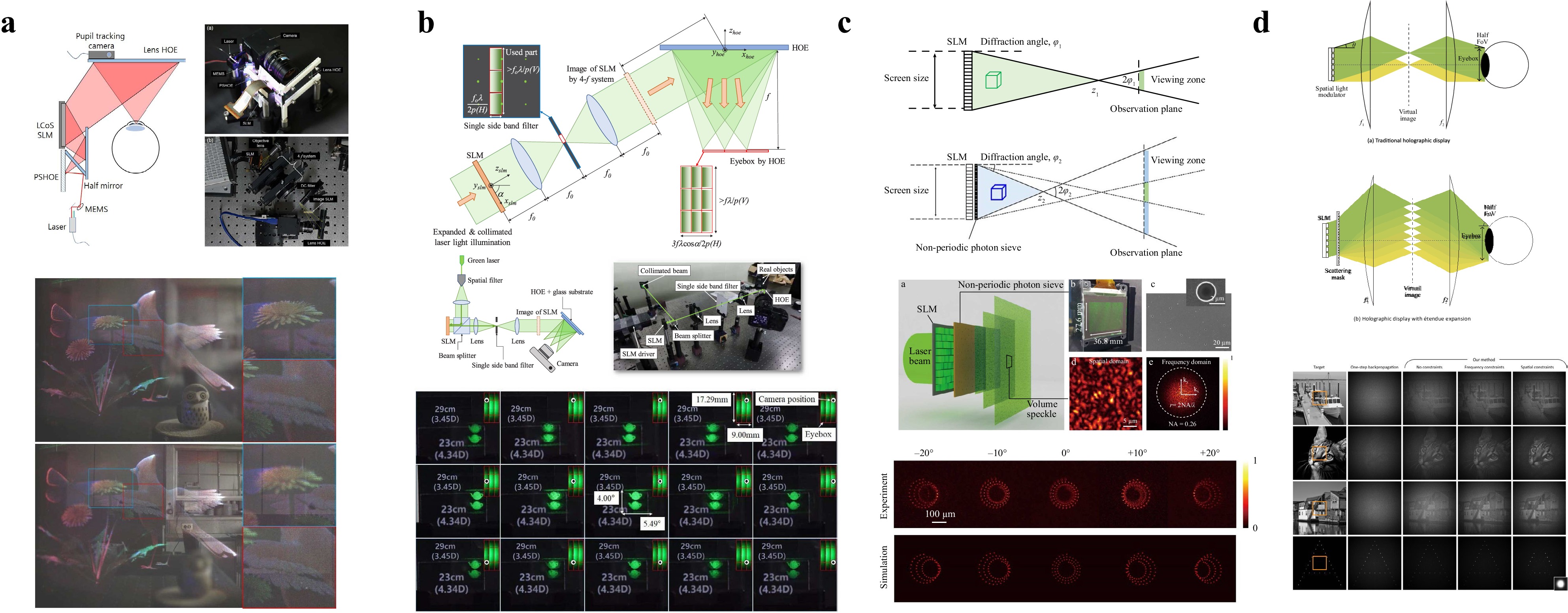
Fig. 9 Eyebox and FoV expansion of holographic NEDs: a eyebox steering64, b eyebox replication65, c eyebox expansion using photon sieve66, and d FoV expansion using random phase mask67. Images reprinted with the following permissions: a64, d67 from ACM (Association for Computing Machinery); b65 from Optica Publishing Group; c66 (CC BY 4.0).
Typical approaches for expanding the eyebox include eyebox steering and eyebox replication, as illustrated in Fig. 9a, b, respectively. In the eyebox steering method64 depicted in Fig. 9a, the laser illumination direction on the SLM is dynamically controlled to steer the eyebox position that is formed around the focal spot of the combiner HOE in front of the eye. A laser beam is reflected by a micro-electromechanical system (MEMS) mirror and diffracted by an HOE (PSHOE), where an array of point sources is recorded. The diffracted light diverges from the selected point source position in the PSHOE and illuminates the SLM. In eyebox steering, the MEMS mirror angle is controlled such that different point sources are selected in the PSHOE, thereby illuminating the SLM in the corresponding directions.
Fig. 9b depicts the eyebox replication approach65. The light from the SLM is first filtered using 4-f optics to pass only a horizontal single sideband, so as to remove the DC, conjugate, and horizontal high-order diffraction terms. Unlike typical holographic displays, vertical high-order terms are maintained deliberately. The resultant vertically long eyebox is horizontally replicated and tiled together using an HOE combiner. The HOE combiner works as a horizontally multiplexed concave mirror, which forms three replicas of the eyebox. The spacing between the focal spots of the HOE is designed such that the eyebox is tiled without overlapping or gaps. The resultant 2D array of elementary eyeboxes offers a wide range of eye positions. The distortion that is observed when the eye is placed at the boundary with the elementary eyebox is remedied by wrapping the angular spectrum of the CGH accordingly.
Although the eyebox steering and replication approaches illustrated in Fig. 9a, b expand the effective eyebox, they require eye position information, which necessitates an additional eye pupil tracking system. Fig. 9c presents another approach that increases the eyebox without requiring the eye position information. In holographic NEDs, the eyebox is primarily determined by the maximum diffraction angle of the SLM, which is provided by the pixel pitch. As the pixel pitch cannot be reduced arbitrarily, the SLM diffraction angle and eyebox of the NED are limited. In the work66 depicted in Fig. 9c, a photon sieve is attached to the SLM to reduce the effective pixel pitch. The tiny randomly distributed apertures in the photo sieve increase the diffraction angle, thereby expanding the eyebox of the system. Note that because the eyebox is expanded over the SBP limit of the SLM, the reconstruction is inevitably distorted and degraded if the usual CGH techniques that assume an ideal reconstruction system are used. This quality degradation is mitigated by solving the CGH optimization problem, which minimizes the difference between the ideal target 3D images and reconstructed images. Unlike eyebox steering and replication, this approach does not require the eye position, which is advantageous.
A similar approach can also be applied to FoV expansion67, an example of which is presented in Fig. 9d. A random phase mask is placed on the conjugate plane of the SLM, thereby increasing the diffraction angle above the SBP limit. The increased diffraction angle results in an enhancement of the FoV, so that larger 3D images are presented to the user. CGH synthesis is again formulated as an optimization problem, providing 3D images in a larger FOV with minimized quality degradation. An enhancement of the FoV of up to 16× has been demonstrated using this approach.
-
The human visual system has a non-uniform resolution distribution across the FoV. Most cone photoreceptors are concentrated in the fovea, thereby providing high resolution only in that area. Based on this observation, foveated displays present high-resolution images only around the eye gaze point, while displaying the peripheral areas with low resolution68,69. The required number of pixels to cover the entire FoV is reduced, which enables more efficient and faster operation.
Foveated display techniques have recently been applied in holographic AR/VR NEDs. The studies applied the foveated display concept either to CGH synthesis70-73 or to the system configuration74, 75. Fig. 10a, b provide examples of foveated CGH synthesis for holographic AR/VR NEDs. CGH synthesis is a computationally intensive task, for which various acceleration techniques have been proposed. Foveated CGH synthesis reduces the computational load by reducing the target image resolution in the peripheral areas. As illustrated in Fig. 10a, this is achieved by synthesizing the full FoV CGH of the 3D scene that is represented in the low-resolution triangular mesh model, and subsequently updating it progressively to high-resolution meshes only within the foveated area72. In the work73 depicted in Fig. 10b, a similar concept is applied to the layered image model. The foveal and peripheral images are prepared at different sampling rates, and the corresponding holograms are synthesized and combined, thereby reducing the overall computation time.
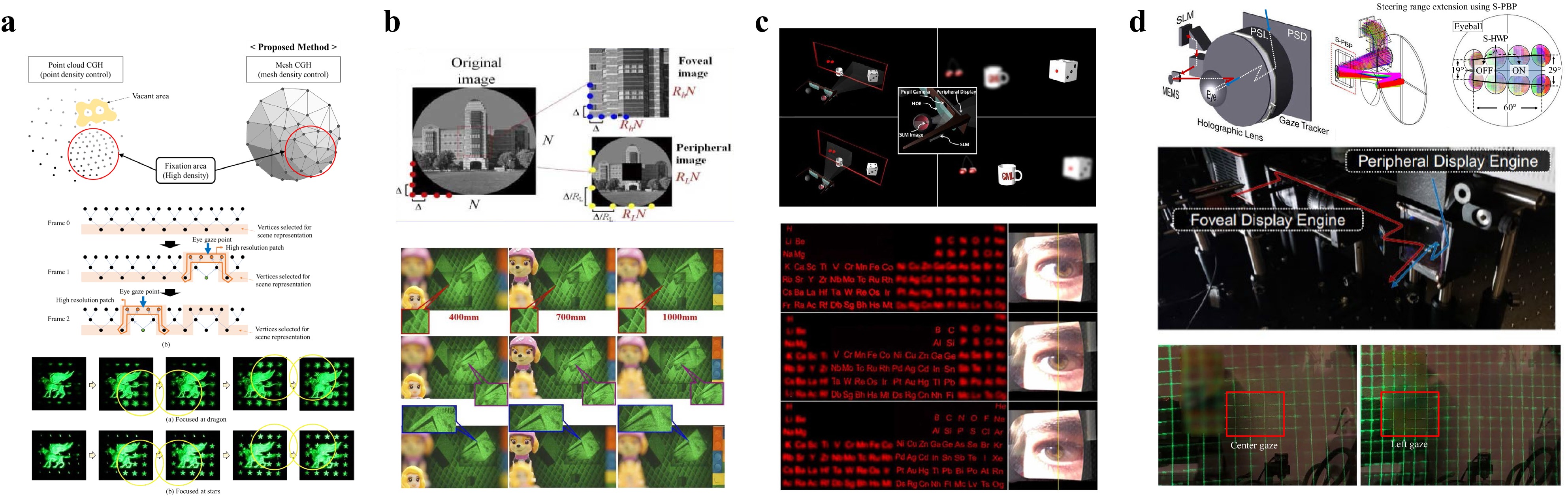
Fig. 10 Foveated holographic displays: a foveated CGH for 3D mesh models72, b foveated CGH for layered images73, c foveated holographic display with an SLM image at the eyeball rotation center74, and d foveated holographic display using a MEMS mirror and LC device75. Images reprinted with the following permissions: a72, b73 from Optica Publishing Group; c74, d75 (CC BY 4.0).
The techniques depicted in Fig. 10c, d apply a foveated display to the system configuration. In addition to the holographic display module, which accounts for the foveal display, a display panel for the peripheral area is prepared. During operation, the holographic display module presents high-resolution 3D images with a small FoV around the foveated area, whereas the 2D display panel presents peripheral images in a wide FoV with low resolution. In implementation, the dynamic optical steering of the foveated holographic display area following the gaze direction is a challenging issue. The work74 in Fig. 10c uses an optical configuration that locates the SLM image at the rotation center of the eyeball. Because the SLM image remains in the eyeball regardless of the eyeball rotation, the holographic 3D images follow the gaze within the full FoV. In another method75, as depicted in Fig. 10d, a MEMS mirror is controlled to steer the holographic foveal area following the gaze. Moreover, an LC deflector is used to expand the steering range further. Although efficient and compact implementation remains an issue, this type of foveated holographic display is attractive and exhibits high potential in that it presents wide FoV images in an efficient manner, without sacrificing the perceived 3D image quality and focus cues of the holographic displays.
-
Speckle noise is a long-standing problem in holographic display. A speckle is a grain-shaped random spatial fluctuation in intensity. In holographic displays, the complex field within the resolution spot of the eye interferes, resulting in speckle noise, which degrades the image quality. Because speckle noise is inherent to a coherent imaging system, its suppression at the perceivable level is of practical importance.
Fig. 11 depicts recent methods for suppressing speckle noise. In Fig. 11a, a temporal averaging technique of the random speckle pattern is used76. The same 3D images are generated with different random phases in each sub-frame, creating uncorrelated speckle patterns. These speckle patterns are averaged by temporal multiplexing, thereby reducing the perceived speckle contrast. The speckle contrast reduction is proportional to the square root of the number of sub-frames in the temporal multiplexing. In the work shown in Fig. 11a, a fast SLM, namely a digital micro-mirror device, is used to accommodate fast temporal multiplexing along with structured illumination to expand the viewing area. Speckless holographic video presentation at 60 Hz has been successfully demonstrated. In the method77 illustrated in Fig. 11b, the object points of the 3D image are divided into spatially interleaved groups and displayed sequentially. The spacing between the object points in the same group is adjusted to be larger than the resolution spot of the eye, which prevents interference. Interleaving can also be applied to the angular spectrum domain78, as shown in Fig. 11c. In each frame, the holographic 3D image is reconstructed with a set of angularly interleaved plane carrier waves. The angular separation of the plane carrier waves in each frame is set to be larger than the eye pupil, which again prevents speckle noise. With temporal multiplexing, the plane carrier waves scan the entire angular range, providing a natural defocus blur. The spatial and angular interleaving techniques depicted in Fig. 11b, c require temporal multiplexing, but the required number of sub-frames is much less than that of the random speckle pattern averaging technique. Finally, instead of a coherent laser, a partially coherent light source or an LED can be used to suppress speckle noise. The extended linewidth and emitting area of the LED reduce the temporal and spatial coherence of the light, thereby suppressing the speckle noise. However, the reduced temporal and spatial coherence also blurs the reconstruction, resulting in a tradeoff relationship between the speckle noise and image sharpness. In the work79 shown in Fig. 11d, this tradeoff relationship was thoroughly analyzed, with the proposal of an optimal partially coherent light source.

Fig. 11 Speckle reduction techniques: a temporal averaging of uncorrelated speckle patterns with structured illumination76, b spatial interleaving of object points77, c angular spectrum interleaving78, d partial coherence of light source optimization79. Images reprinted with the following permissions: a76, b77, c78 from Optica Publishing Group; d79 (CC BY 4.0).
-
Real-time CGH synthesis and photorealistic image quality are crucial for the practical and widespread application of holographic AR/VR NEDs. In recent years, significant progress has been made in this regard with the aid of emerging neural network techniques.
The application of a neural network to CGH synthesis was pioneered by the work80 shown in Fig. 12a. A basic U-Net architecture is trained to output the CGHs of the target images without a physical wave propagation calculation, which significantly reduces the computation time. The neural network-based CGH synthesis is subsequently further developed to generate CGHs of multi-depth 3D objects with a reconstruction quality that is comparable to the physical wave calculation, as shown in Fig. 12b81. The image quality and processing speed were significantly enhanced in the work82 depicted in Fig. 12c. In this method, a neural network is trained with a random scene generator, which creates a large training dataset, thereby contributing to the enhancement of the image quality. A sophisticated training strategy, including the designed depth distribution in the synthesized random scene, an occlusion-capable hologram synthesis algorithm, and a loss function that measures the quality in both the reconstructed 3D image volume and the intermediate hologram plane, enables high image quality reconstruction, which has rarely been observed in previous holographic displays. Real-time operation at 60 Hz and with 1080 p resolution is another benefit of this study.
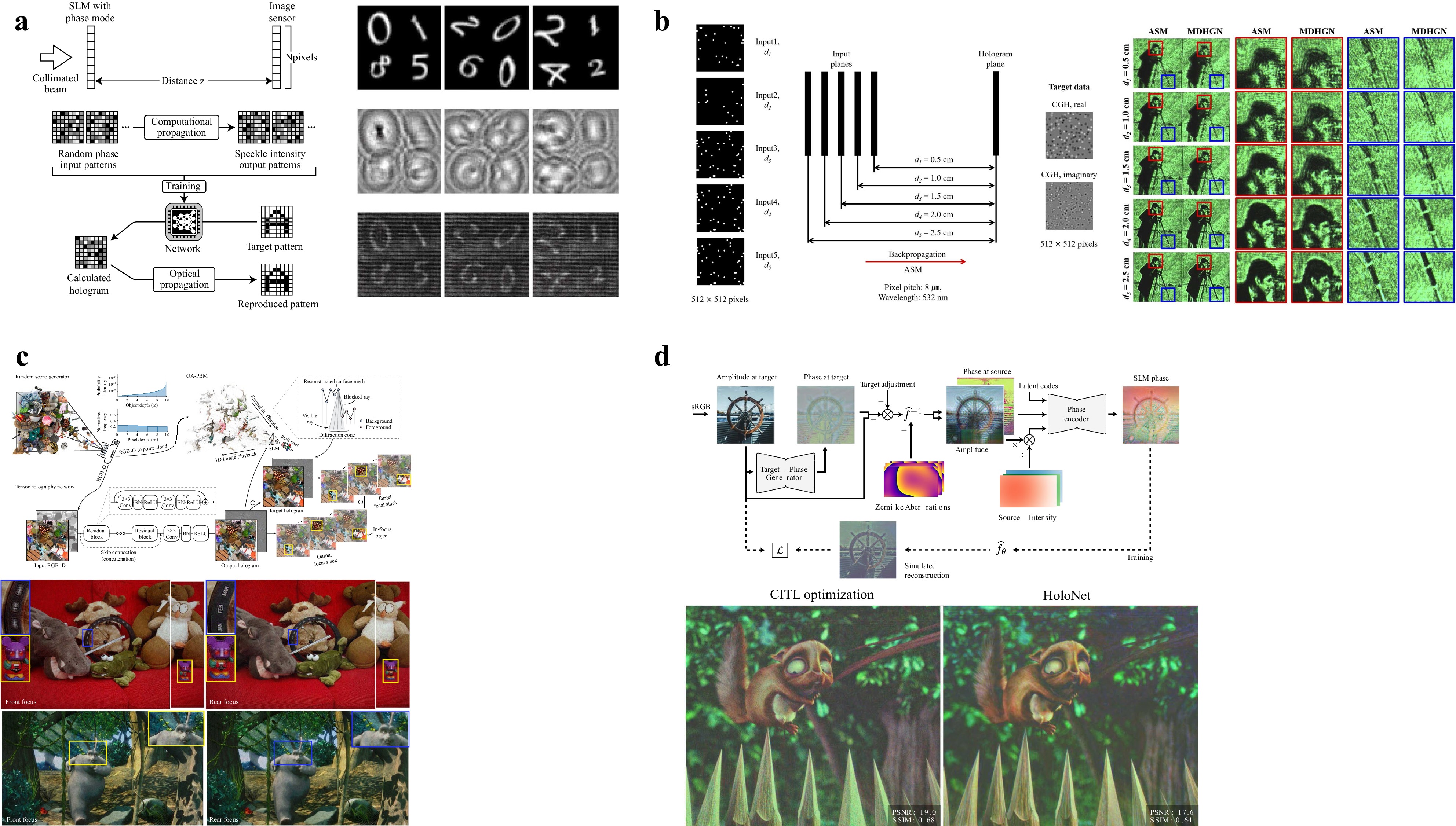
Fig. 12 Image quality and CGH synthesis speed enhancement using neural network: a CGH synthesis using a U-Net80, b multi-depth CGH synthesis81, c real-time high-quality CGH synthesis for RGBD input82, d propagation model calibration using camera-in-the-loop feedback and neural holography83. Images reprinted with the following permissions: a80, b81 from Optica Publishing Group; c82 from Springer Nature; d83 from ACM (Association for Computing Machinery).
Most conventional CGH techniques, including those shown in Figs. 12a−c, assume an ideal display system. However, a specific implementation of a physical display system deviates from the ideal one in many aspects and causes significant image quality degradation. The work83 presented in Fig. 12d tackled this problem by incorporating an active feedback configuration. As observed in the figure, a camera is placed in the eyebox to capture the reconstruction. In each iteration, the CGH is updated to reduce the error between the target and reconstructed images. This iterative update of the CGH does not rely on the ideal wave propagation model, but directly considers the physical system and exhibits very high-quality holographic reconstructions. This technique has been further developed to construct an interpretable propagation model considering non-uniform laser illumination, per-pixel phase nonlinearity of the SLM, and aberrations of the system optics. This model was subsequently used to build and train a neural network that outputs the optimized CGH without iterative optimization. Using this technique, 40 Hz CGH synthesis at 1080 p resolution with high image quality was demonstrated. Although the work in Fig. 12d is limited to the target image in a single plane, its extension to multi-depth 3D images84 has also been reported in recent work. The neural network-based approaches introduced in this section provide a novel breakthrough of the limitations posed by the physics-based calculation of the ideal wave propagation model, and significant progress is expected in this field.
-
In this article, various holographic techniques that have been applied to AR and VR NEDs have been introduced. Holographic techniques can be used for either static or dynamic optical components. As a static optical component, the holographically recorded volume grating; that is, the HOE, offers a wide range of applications. HOEs are thin and light, which is crucial in AR and VR NEDs; moreover, the angular, wavelength, and polarization selectivity enable various optical functions, making them an ideal replacement for conventional bulk optics. The recently emerging metasurface lenses have provided an even thinner form factor with a higher NA, demonstrating their potential as AR and VR optics. Holographic displays have been applied to AR/VR NEDs as dynamic displays. The unique wavefront reconstruction capability of holographic displays is used to present natural 3D images with full monocular focus cues, while correcting aberrations in the NED optics and eye lenses. Recent progress has enhanced holographic NEDs in various aspects, including eyebox and FoV expansion, speckle suppression, and foveated presentation. Finally, the combination of holographic techniques with neural networks has exhibited significant performance enhancement in terms of the CGH synthesis speed and reconstruction image quality, making real-time and photorealistic holographic NEDs feasible in the near future.
-
National Research Foundation of Korea (NRF-2017R1A2B2011084).
Holographic techniques for augmented reality and virtual reality near-eye displays
-
Jae-Hyeung Park1, *, ,
 ,
, -
Byoungho Lee2, *, ,
- Light: Advanced Manufacturing 3, Article number: 9 (2022)
- Received: 25 September 2021
- Revised: 19 January 2022
- Accepted: 20 January 2022 Published online: 22 February 2022
doi: https://doi.org/10.37188/lam.2022.009
Abstract: Near-eye displays are the main platform devices for many augmented reality (AR) and virtual reality (VR) applications. As a wearable device, a near-eye display should have a compact form factor and be lightweight. Furthermore, a large field of view and sufficient eyebox are crucial for immersive viewing conditions. Natural three-dimensional (3D) image presentation with proper focus cues is another requirement that enables a comfortable viewing experience and natural user interaction. Finally, in the case of AR, the device should allow for an optical see-through view of the real world. Conventional bulk optics and two-dimensional display panels exhibit clear limitations when implementing these requirements. Holographic techniques have been applied to near-eye displays in various aspects to overcome the limitations of conventional optics. The wavefront reconstruction capability of holographic techniques has been extensively exploited to develop optical see-through 3D holographic near-eye displays of glass-like form factors. In this article, the application of holographic techniques to AR and VR near-eye displays is reviewed. Various applications are introduced, such as static holographic optical components and dynamic holographic display devices. Current issues and recent progress are also reviewed, providing a comprehensive overview of holographic techniques that are applied to AR and VR near-eye displays.
Research Summary
AR and VR: Near-eye displays are advancing with holographic techniques
Near-eye displays are glass-type wearable display devices that enable immersive presentation of virtual images in AR and VR applications. Compact form-factor, light weight, large field of view, wide eyebox, and natural 3D image presentation with proper focus cues are crucial requirements of the near-eye displays for a comfortable viewing experience and natural user interaction. In recent years, holographic techniques have been actively applied to implement these requirements, overcoming the limitation of the conventional bulk optics and 2D display panels. Jae-Hyeung Park from Inha University and Byoungho Lee from Seoul National University review the recent progress in the application of the holographic techniques. By covering various applications such as static holographic optical components and dynamic holographic display devices, they provide a comprehensive overview of holographic techniques that are applied to AR and VR near-eye displays.
Rights and permissions
Open Access This article is licensed under a Creative Commons Attribution 4.0 International License, which permits use, sharing, adaptation, distribution and reproduction in any medium or format, as long as you give appropriate credit to the original author(s) and the source, provide a link to the Creative Commons license, and indicate if changes were made. The images or other third party material in this article are included in the article′s Creative Commons license, unless indicated otherwise in a credit line to the material. If material is not included in the article′s Creative Commons license and your intended use is not permitted by statutory regulation or exceeds the permitted use, you will need to obtain permission directly from the copyright holder. To view a copy of this license, visit http://creativecommons.org/licenses/by/4.0/.

 DownLoad: