


HTML
-
Not long after the first demonstration of holographic images by Leith and Upatnieks1, as well as by Denisyuk2, a similar technique was used by De Bitetto and others to display motion picture holograms3, 4. As the name indicates, a motion picture hologram uses a rapid succession of static holographic images to reproduce the effect of movement in 3D. Because of these successes, it was hoped at the time that a holographic television would be developed soon after. Unfortunately, more than 50 years later, there is still no holographic television in sight.
Compared to motion picture, a holographic display system needs to capture, transmit, and render 3D information. In the case of an interactive display system, such as a computer screen, there is the additional constraint that real-time manipulation of 3D data is required. This makes a universal holographic 3D display much more challenging to develop than the simple successive projection of pre-recorded holograms.
To provide a sense of how difficult a holographic display is compared to other forms of telecommunication, it is useful to consider the commonly used data rate metric. Even though focusing on the data rate does not take into account some other technological aspects, such as rendering complexity, it does allow comparison over a large range of techniques. For a holographic display to have an acceptable field of view of perhaps
$ \pm 45^\circ $ (diffraction angle$ \theta $ ), the law of diffraction indicates that the diffractive element size$ d $ for a central wavelength of$ \lambda = 500 $ nm should be on the order of 350 nm.$$ d = \frac{\lambda}{2 sin \theta} $$ (1) It should be noted that elements should be approximately 10 times smaller than predicted by equation 1 to achieve high-efficiency blazed diffraction gratings.
Given a 70 cm diagonal-screen television set (i.e.,
$ \mathrm{50\; cm \;\times\; 50\; cm} $ ), the number of active elements must be on the order of$ 2\;\times\;10^{12} $ . To accommodate human vision perception, the display requires a minimum refresh rate of 60 Hz (corresponding to the flicker vision threshold), and at least three colors to fill the eye chromaticity gamut. The gray-level resolution for a conventional display is generally at least 8 bits (256 levels). For the sake of comparison, we will use the same number of phase levels for a hologram, although phase levels are related to efficiency and not shades of gray in holograms. It is even possible to reconstruct a 3D image with a binary hologram by sacrificing some spatial bandwidth and efficiency5. The resulting data rate for such a display, excluding any type of compression algorithm, would be$$ \begin{split} & \mathrm{pxl\; nbr \times rep.\; rate \times res. \times colors}\\ & = 2\times10^{12}\times 60 \times 8 \times 3 \approx 3\times 10^{15}\; \mathrm{b/s.} \end{split} $$ (2) Fig. 1 plots the data rate in bits per second for different telecommunication systems according to the time of their introduction. Starting with the optical telegraph (or Chappe's semaphore) presented to Napoleon Bonaparte in 1798, the optical telegraph had a typical rate of transmission of approximately 2 to 3 symbols (196 different types) per minute, or 0.4 b/s. Consequently, the electrical telegraph, popularized in the early 1840s using Samuel Morse's code, achieved a rate of approximately 100 b/s. Graham Bell's telephone was introduced in 1876 and supported voice frequency transmission up to 64 kb/s6. The early NTSC black and white electronic television, available in the 1940s, had 525 interlaced lines and displayed images at a rate of 29.97 frames per second at a bit rate of 26 Mb/s7. The color NTSC format was introduced 10 years later and tripled the black and white bandwidth to accommodate red, green, and blue channels8. More recently, the digital video format makes it easier to establish the bit rate based on pixel count (excluding compression) with HDTV 720p@1.33 Gb/s in 1990, ultra-HDTV 2160p(4K)@12.7 Gb/s in 2010, and currently 4320p(8K)@47.8 Gb/s. Note that these values are for uncompressed data feeds, and for the sake of comparison, do not include any type of compression algorithm.
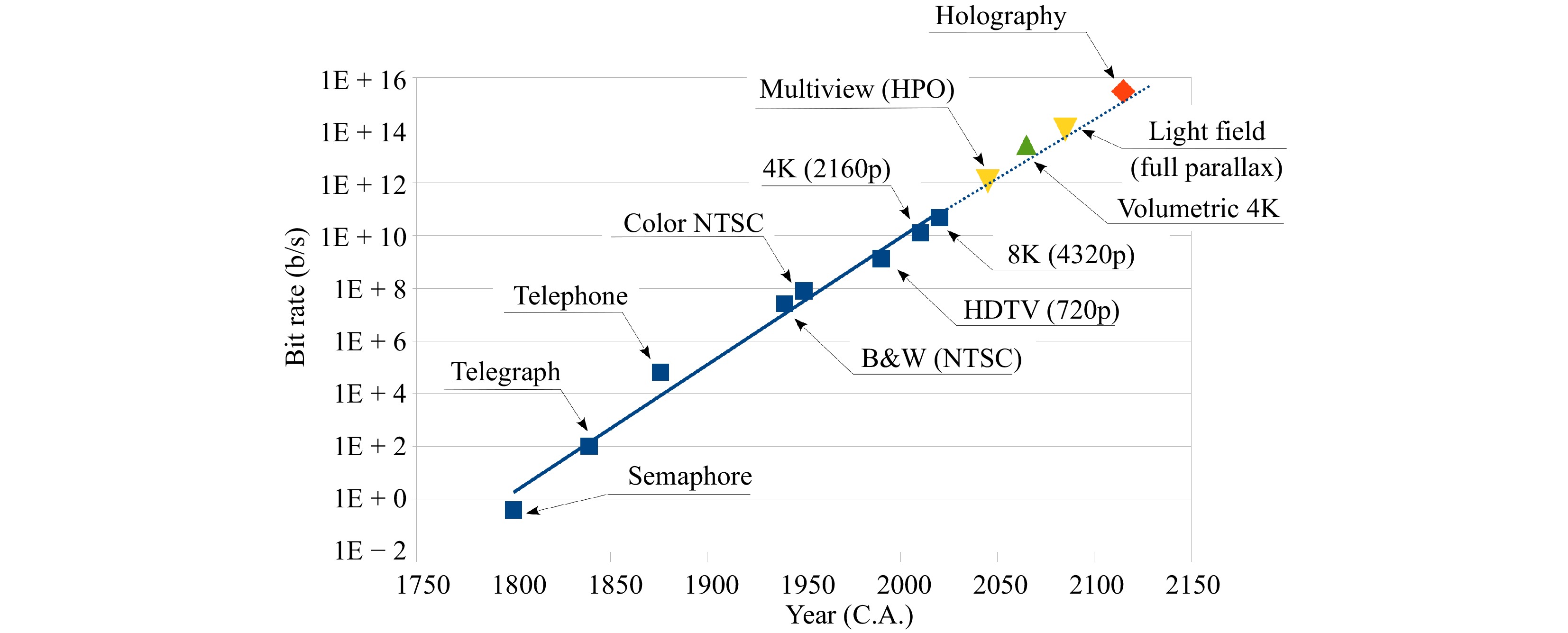
Fig. 1 Stairway to holography: approximate bit rate magnitude of various telecommunication devices according to their year of introduction.
The evolution of the bit rate for telecommunication devices plotted in Fig. 1 shows a trend that can be extrapolated to predict the emergence of holographic displays with a data rate of
$ 3\;\times \;10^{15} $ b/s. This extrapolation estimates the emergence of a commercial holographic display by 2100. Although this extrapolation is indicative of the difficulties ahead, it is also very encouraging. The date of 2100 is by no means an inescapable natural law. Similar to the doubling of the transistor count on chips every year, this prediction can be affected in one way or another by the amount of effort invested in the research and development of holographic display technologies.In this manuscript, we investigate the reasons why holography is still perceived to be the ultimate technique to develop a commercial 3D display, review the progress that has been accomplished toward this goal, and discuss the missing technologies that are still needed to promote the emergence of such a 3D display.
-
Understanding the human visual system and how it perceives the third dimension is key to developing a 3D display9−11. The human visual system takes input from many different cues to determine depth perception. It should be noted that most of these cues originate from 2D phenomena. Among these are shading, shadowing, perspective, relative size, occlusion, blurriness, and haze. The example presented in Fig. 2 shows how three simple discs, presented on whatever 2D display you are reading this article on, are interpreted as 3D balls owing to these cues.
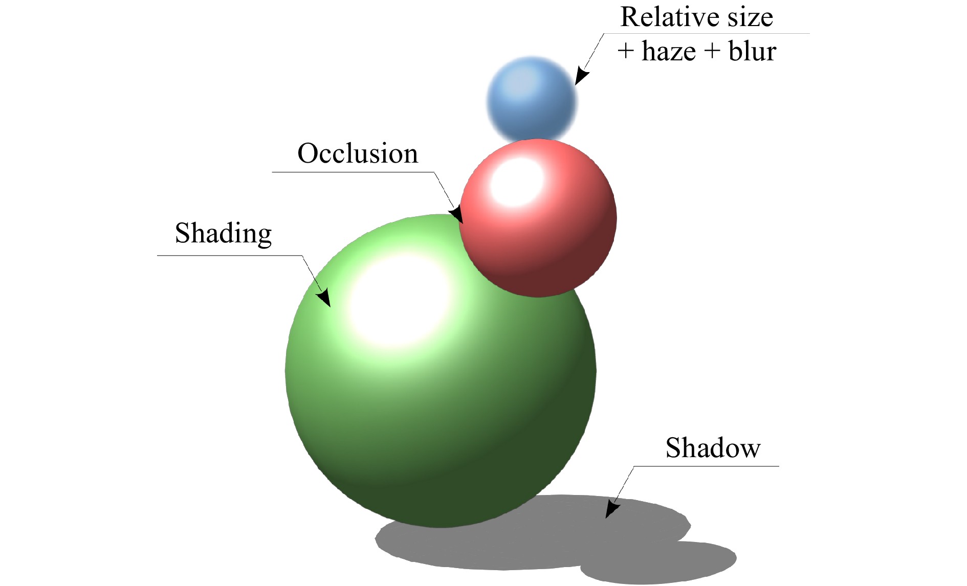
Fig. 2 Examples of some of the 2D visual cues that affect depth perception.
Because these 2D cues are processed by the human visual system to determine the depth of a scene, then a painting, a photograph, or a movie is intelligible as long as these cues are correctly reproduced. When they are not, this leads to optical illusions such as infinite staircases and other impossible shapes.
The same applies to any 3D display system, which must, first and foremost, represent these 2D cues before introducing any additional cues. Additional 3D cues are stereo disparity, motion parallax, and accommodation. We briefly review these cues in the following sections.
-
Stereo disparity is the change in parallax of the scene observed between the left and right eyes. It only requires that two images be reproduced, and as such, is the most technologically manageable 3D cue. It is so manageable in fact that the introduction of stereoscopic displays pre-dates the invention of photography. The first system was invented by Sir Charles Wheatstone in the early 1830s using drawn images12. This was then followed by taking pictures from two positions, or with a camera having two objectives.
When a stereo projection is meant for a single individual, such as a head-worn display, it is relatively easy to keep the left and right views separated. Images are separated by simply introducing a physical partition between both eyes13. For a larger audience, the separation between left and right views is often achieved by having the viewers use eyewear with different left and right lenses. The left and right image coding can be achieved using color (anaglyphs), orthogonal polarization, or alternating shutters14, 15.
From a user perspective, the eyewear requirement for stereo display has been accepted in special venues such as theaters, where large productions continue to be released in stereoscopic 3D. However, the commercial failure of stereoscopic 3D television seems to indicate that for everyday experience, the public is not enthusiastic about wearing special glasses in their own living rooms16.
-
Autostereoscopic displays achieve stereoscopy without the need for special glasses. The left and right views are directly projected toward the viewer’s intended eyes using parallax barriers or a microlens array17−19. To ensure that the correct eye intersects the correct projection, autostereoscopic systems require that the viewer be located at a particular position. This inconvenience has proven sufficient to limit the adoption of autostereoscopic 3D television by the consumer market20. It should also be noted that autostereoscopic systems with an eye tracking mechanism that mitigates the fixed viewer zones have been developed, but have not achieved wide popularity21−23.
-
Motion parallax requires many views to be projected, allowing the viewer to see the correct parallax even when moving in front of the display. The density of the different views that are projected needs to be such that the autostereoscopic information is correctly reproduced. Therefore, at least two views per inter-pupillary distance are required. However, to achieve a smooth transition from one perspective to the next, a much larger density of views is required24. The optimum view density depends on the exact configuration of the display and the expected viewer distance, but numbers are on the order of one view per degree25−27.
In most of the literature, a display that reproduces motion parallax is called a "multiview" or "multi-view" display while a "light-field" display reconstructs 3D images based on the concept of ray-optics and integral imaging28−32. In a multiview display, the display is designed such that the motion parallax can be reproduced smoothly when a viewer’s position changes. This is considered a multiview-type autostereoscopic display. However, when the display is also capable of reconstructing virtual or real images, it is usually called a light-field display.
We can apply the same data rate computation introduced earlier for the different types of telecommunication devices (see Fig. 1) to a multiview (or light-field) display that reproduces motion parallax. In this case, we find that for a display with 2160p(4K) lateral resolution to reproduce motion parallax with a ±45° field of view, the bit rate is on the order of
$ 12.7\; \times\; 90^2 = 10^{5}\; {\rm{Gb/s}} $ . The square factor arises from the fact that both horizontal and vertical parallaxes are considered in this case.Because the human visual system involves a mostly horizontal inter-pupillary distance, and lateral movement is favored over vertical movement, horizontal parallax is more important than vertical parallax. The latter is often discarded in multiview displays to allow a lower data rate of
$ 12.7 \;\times \;90 = 10^{3} \;{\rm{Gb/s}} $ .When the viewer remains motionless in front of a multiview display, the observed parallax provides an experience similar to that of autostereoscopic displays33. However, because of the much larger number of views, a light-field display is not subject to the same limited number of view zones as autostereoscopic systems34. Therefore, user experience is much better, and acceptance is more likely.
Considering their somewhat achievable data rate and advantages over auto-stereoscopy, multi-view and light-field displays are currently the subject of intense research35−40. This technology certainly represents the next 3D display platform that will appear in the marketplace, and some specialized applications have already started to emerge41.
-
The vergence-accommodation conflict is the Achilles heel of all the display systems that we have introduced thus far: stereoscopic, autostereoscopic, multiview, and light-field (with some exception for the latter) and occurs when mismatched visual 3D cues are presented to an observer. The vergence-accommodation conflict occurs because the images projected by these displays are located at a fixed distance, thus producing a constant accommodation cue that cannot be adjusted, whereas vergence is provided by the parallax, which can be reproduced, and thus may vary within a scene. Disparity between accommodation and vergence cues can create a conflict in perception. This conflict leads to some visual discomfort, which is well documented in the literature42−45.
Light-field displays can reproduce some amount of accommodation when the ray density is sufficiently large. This condition is often referred to as a super-multiview46, 47. Accommodation occurs in a light-field display because the image plane can be moved in and out of the display plane. This is achieved by directing the light rays from different sections of the panel toward one voxel region, as shown in Fig. 3a.
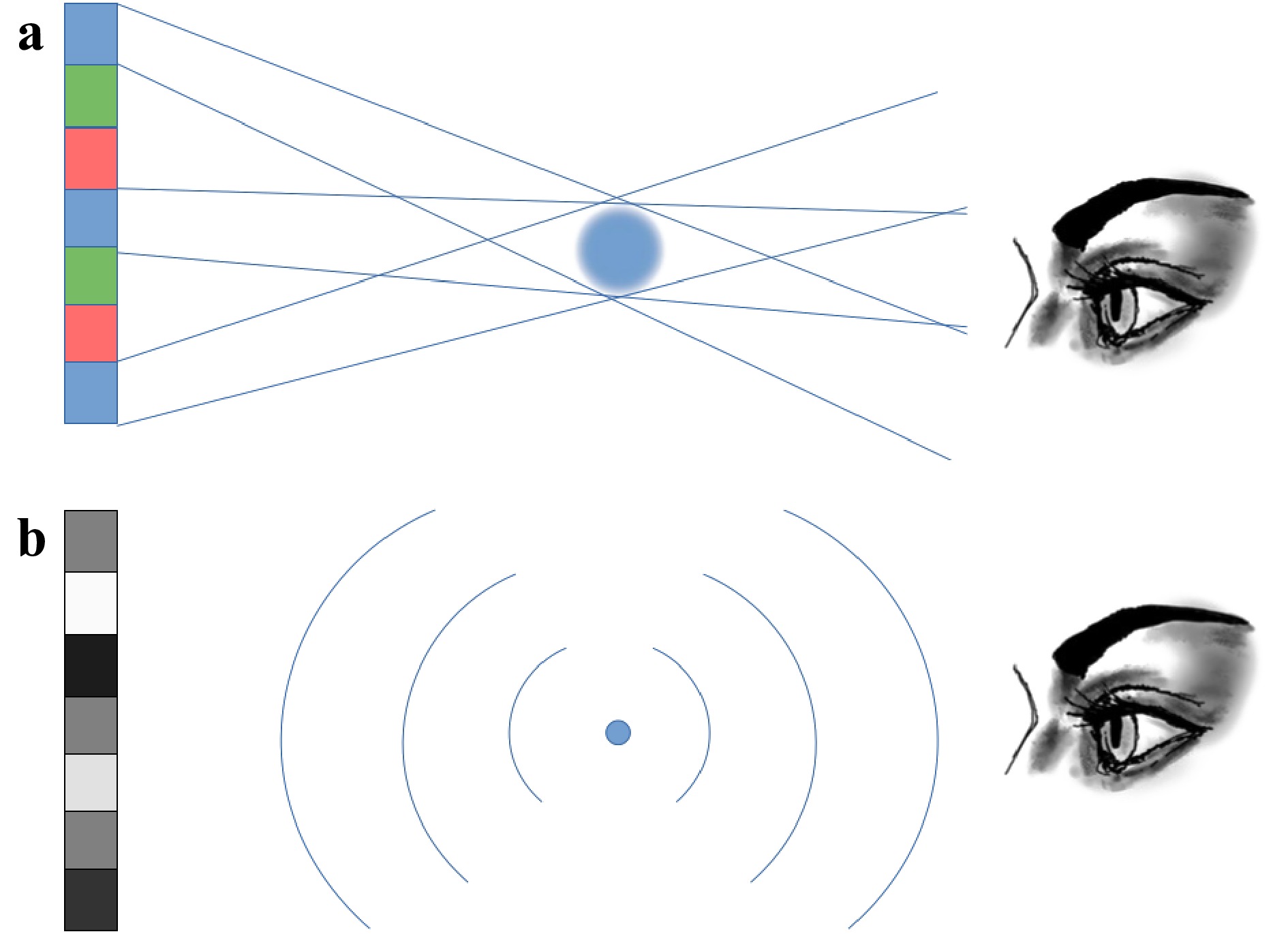
Fig. 3 Illustration of the projection of a voxel out of the emission plane by
a a light-field display, and b a holographic display.However, there is some belief that if the view density keeps increasing in a light-field display, the accommodation distance can be extended at will. This belief arises from the extrapolation that light-field displays approximate a wavefront curvature by using line segments. If these segments are sufficiently small, they may become indistinguishable from the true wavefront curvature. Unfortunately, this ray-tracing simplification does not occur because diffraction along the pixel edges takes place, limiting the voxel resolution. Even with a pixel density in the 100s per degree, when an object is projected too far from the plane of the light-field display, it becomes blurry because of the diffraction among pixels. This diffraction effect cannot be avoided and intrinsically reduces the depth resolution and accommodation of light-field displays48, 49.
To eliminate the diffraction phenomena experienced with smaller pixel sizes, strong coherence among pixels is required so that the light-field display becomes indistinguishable from holography.
The difficulty of reproducing accommodation induces visual discomfort by having to limit the display depth of the field. To reproduce a voxel out of the plane of the display, the light should be focused at that point by the optical system. Without the capability to refocus subpixels at will, the light-field display can only produce a flat wavefront from the emission plane. As presented in Fig. 3a, when a light-field display attempts to reproduce a voxel that is too far away from the emission plane, the voxel invariably becomes blurry.
To address this problem, researchers have developed multiplane light-field displays50−52. This is possible because the plane of emission can be refocused by optical elements and moved along the view depth. However, this requires some multiplexing to generate different planes in time or space, which increases the bandwidth required by the system. Another aspect that should not be overlooked is that occlusions between different planes are difficult to control when there are many view zones53.
-
Volumetric displays have voxels located in 3D space and are affected by the same occlusion problem as a multi-plane light-field display. For both systems, the occlusions can only be correctly reproduced for one point of view54, 55. Some systems (both volumetric and light-field) use an eye tracking mechanism to re-calculate the occlusions and present the correct image wherever the viewer is located56. However, only one correct perspective can be achieved, precluding its application for multiple observers.
In a volumetric display, the occlusion problem occurs because the emission of the voxel is omnidirectional, and there is no absorptive voxel. Nevertheless, volumetric displays have the advantage of being able to reproduce the field depth without resolution loss. They can be somewhat more natural to view when they do not use a screen to display an image. In this case, the image appears floating in thin air, which has a dramatic effect on the viewer’s perception55, 57, 58.
Volumetric displays also have the disadvantage of not being capable of projecting images outside a limited volume. The image depth is bounded by that volume, and a deep landscape or object that seemingly reaches out of the display cannot be reproduced54.
The mathematical computation of the bit rate for a volumetric display is as simple as multiplying the resolution of a 2D screen by the third dimension, refresh rate, and dynamic range. In Fig. 1, the data rate for a 4K volumetric display is
$$ \begin{split} \begin{split} & \mathrm{x \times y \times z \times rep. rate \times res. \times colors }\\ & = 4096 \times 2160 \times 1000 \times 60 \times 8 \times 3 = 1.3 \times 10^{13}\; \mathrm{b/s.} \end{split} \end{split} $$ (3) However, because volumetric display setups are easily scalable, lower-resolution systems can be readily used to showcase the potential of the technology59−61.
-
Since the studies by Leith, Upatnieks, and Denisyuk, static holograms have demonstrated that the technique is capable of reproducing all the cues that the human visual system uses to comprehend the three dimensions1, 2. By using high quality photosensitive materials, it is now possible to copy existing artifacts and display convincing holographic reproductions in full color62, 63. The question that remains is how to do the same with a refreshable display.
There are three fundamental problems to be solved to create a holographic television: the computation of the holographic pattern from the 3D information, the transmission of the data from where it is captured to where it needs to be displayed, and the reproduction of the holographic pattern on the screen to display the 3D image.
-
The calculation of the diffraction pattern from a 3D image is based on the physical model of light propagation. The Kirchhoff and Fresnel diffraction integrals provide the value of the field at a distance
$ z $ from an aperture of arbitrary shape5. Early studies on computer generated holograms (CGHs) were undertaken in the late 1960s by Lohmann, Brown, and Lesem64−66. Although the mathematical equations have been well-known for a very long time, their actual computation is far from trivial and has often been referred to as the "computational bottleneck"67. Even today, the number of operations per second (flops) needed to compute the size and location of the diffraction elements in real time is beyond the capabilities of any computer.To provide a sense of scale, and following the approach by Slinger et al.68, a brute force approach computation for a 720p (
$ 1280\; \times \;720 $ ) holographic display requires$ 100 \;\times \;100 $ diffractive elements per pixel for full parallax, and 4000 multiplication and accumulation calculations per element at a rate of 60 Hz, and for three colors, this computes to$ 1280\; \times\; 720 \times 100\; \times \;100\; \times\; 4000\; \times \;3\; \times \;60 \;= $ $ \; 6.6\; \mathrm{peta flops} $ . Simplifications in the way that holograms are computed had to be made.The strongest simplification is to move away from the Fresnel integral and work in the far field with the Fraunhofer integral, which is a Fourier transform. By eliminating the
$ z $ coordinate, the Fraunhofer integral yields the solution of the diffraction pattern for a given intensity field at infinity. Owing to the fast Fourier transform algorithm, a solution can be efficiently computed69. However, Fourier holograms have only a single image plane, so this simplification sacrifices image depth, which is not desirable for a 3D display.It should also be noted that the Fourier transform yields a real and an imaginary solution. These two components correspond to the amplitude and phase values of the hologram. Most of the time, the element used to display the diffractive pattern (such as a spatial light modulator) can only reproduce one or the other, but not both. This means that the result from a single Fourier transform will have a significant amount of noise when reproducing an image. Other sources of noise in holograms originate from the quantization error of the phase levels, diffraction in the pixel structure, and speckle caused by the random phase70.
To reduce the noise and boost the signal, Gerchberg and Saxton developed an iterative algorithm (GS) in 197271. However, the GS algorithm only works for 2D input images and does not accept 3D information. Nevertheless, to obtain some image depth, it is possible to compute individual holograms for different discrete planes72−74. This solution renders both vergence and accommodation. However, because the holograms for the different image planes have been computed separately from one another, and not as a whole 3D scene, occlusions can only be reproduced for a single perspective. This is the same problem previously mentioned regarding volumetric displays. More recently, some algorithms have been developed to address the occlusion problem in multi-plane hologram computations. Such algorithms have demonstrated the capability to render correct occlusions in a limited view zone75−77.
For 3D displays, hologram computations directly based on 3D models can be accomplished78. Although the detailed description of these algorithms is beyond the scope of this article, it should be noted that these algorithms can be separated into two broad categories: wavefront-based methods, and ray-based methods.
In the ray-based technique, the hologram is calculated from incoherently captured 2D image planes of a 3D scene, and relies on the geometric optics formalism of light propagation. The ray-based methods include two distinct categories: holographic stereogram (HS) and multiple viewpoint projection (MVP)79−81. Because they do not compute the wavefront propagation, HS and MVP techniques are much faster than wavefront-based methods and can render photorealistic images82. However, because the full wavefront of the object is not taken into account, ray-based methods can have difficulties rendering some of the 3D optical cues. Moreover, HS techniques experience some limitations in depth of field because the different views are combined incoherently48. Another drawback of the MVP approach is the need to capture or render a large number of images involving small increments in the location of the camera. Otherwise, the motion parallax can be jumpy, and occlusions are not represented well. In a sense, HS and MVP holograms are hybrids falling between light-field displays and holographic displays.
In the wavefront-based methods, the propagation of the light wave is computed starting from a point light source that is illuminating either a point cloud or a polygon representation of the object. The CGH is calculated by simulating the interference between the wavefront coming from the object and another point light source or reference beam. The advantage of these methods is that they natively consider occlusion and parallax cues, so their rendering is accurate. However, this accuracy comes at the cost of high processing demand, as described previously48, 83, 76. This processing demand is driven by the fact that each point of the CGH must take into account the interference between each and every beam projected from the portion of the object that is visible from that location in the hologram plane. When the point on the hologram moves, the perspective of the object also moves correspondingly.
Some of the computations for generating the CGH can be stored upfront in a look-up table84. This information can be retrieved much faster than if it is computed multiple times. There is a fine balance to achieve between large memory storage and computational complexity. To accomplish this balance, different types of algorithms have taken advantage of look-up tables at different stages of CGH computations85−87.
To handle the massive amount of data required to compute 3D holograms in a reasonable amount of time, computations are sometimes performed on specially built hardware accelerators88. This hardware is dedicated to the calculation of the Fresnel phase pattern86, 88−91.
Despite recent advances in the field of computer holography, it seems that from the published images available, the realism of the projected 3D images computed with wavefront-based algorithms requires significant improvement to become convincing (see Fig. 4)75, 92. This is by no means a criticism of the notable achievements accomplished in that discipline, it is rather a testament to how difficult it is to reproduce a fully detailed holographic image.
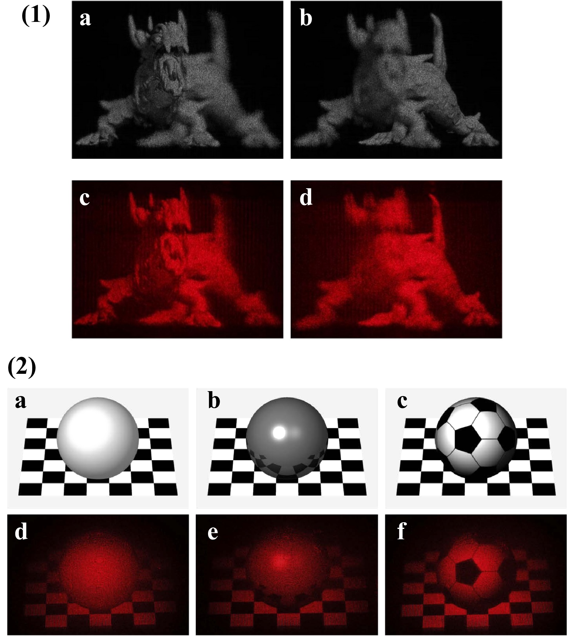
Fig. 4 Examples of optical reconstructions of wavefront-based computer generated holograms from recently published articles.
(1) Reproduced from [75]. Numerical and optical reconstruction results when focusing on the a, c head and b, d tail of the dragon. (2) From [93] presenting rendering images and optical reconstruction images of different surfaces a, d rough surface b, e smooth surface c, f rough surface with texture.In many cases, the holographic image computed using a wavefront-based method lacks texture (see Fig. 4(2)). This should not be surprising, considering that texture rendering considers the finest details of the material surface. This level of detail cannot yet be achieved by computer. A parallel can be drawn with the more familiar world of 2D animation, where early movies depicted blocky characters lacking luster but in modern times, the production team can use any level of photorealism that suits the artistic needs of the story (see for example,93).
Techniques such as machine learning, neural networks, and artificial intelligence have recently been applied with great success to the computation of holograms94−98. In the most general sense, the algorithms associated with these techniques work by training a computing network with some input images (ground truth) and use a camera to observe holograms generated by an optical system. The parameters of the code are optimized by the algorithm to minimize a loss function that forces the holograms to converge toward the original images. Once training is complete, the parameters are frozen, and the algorithm is eventually capable of calculating the hologram of any input image. These techniques are particularly effective at performing fast computations once the training period is complete and at solving the problems associated with texture rendering99, 96. However, for the most part, these algorithms work with 2D images, but are expected to soon be extended to 3D images.
-
The image captured for a holographic display can satisfy the minimum requirements of the human eye and does not have to use coherent illumination and resolve nanometric interference fringes, as is the case with static holograms.
To suit the human eye accommodation, the 3D information to be reproduced can have a depth resolution of only a few centimeters, instead of the nanometers achieved with holography10. Such an image can even be compressed into a 3D mesh model overlaid by a texture pattern, as that used in modern video games. Video games handle this information together with the location of a virtual camera to display a 2D image. In the same way, the game engine could display a 3D image if the display required it. As a case in point, video games can be adjusted to and played using stereoscopic virtual reality headsets.
We know that the amount of data to be transmitted to the display system is not overwhelming and can easily be accommodated by today's technology. However, from a 3D image, the computation of its hologram dramatically increases the amount of information because the diffraction pattern cannot be scaled to accommodate the lateral resolution of the human eye (
$ \approx $ 1 arcminute or 0.3 mrad), but must instead be dimensioned according to the wavelength of visible light ($ \approx 500\; \mathrm{nm} $ ). This scaling can be appreciated in Fig. 1 by comparing the data rate of a volumetric display ($ \approx 10^{13} $ b/s) to a holographic display ($ \approx 10^{15} $ b/s)).Because of this increase in data size, it may be much more efficient to transmit the 3D image/model rather than the holographic pattern100, 101. In this case, the computation of the hologram should be performed at the client (receiver) location. This model is named the "thick client" because the computation is performed locally to avoid overwhelming the long-distance transmission medium. This means that the local site requires significant computational power to support this decoding (see the above section regarding Computed Generated Holograms).
Alternatively, a remote bank of servers can be used to compute the hologram quickly and efficiently. In this configuration, only a "lean client" with limited processing power is needed at the receiver site, whose function is to process the local transmission for display purposes. Under this scenario, the near full amount of data (
$ 10^{14} $ b/s) would need to be transmitted by the server to the client through a "fat pipe" network.A model of the transmission and reproduction of holographic images is presented in Fig. 5, along with the different orders of magnitude of the computation and data rate needed at each stage.
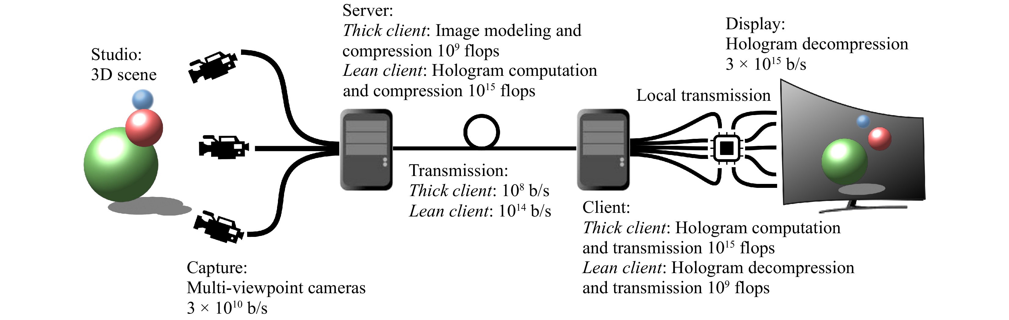
Fig. 5 Schematic of a holographic television transmission process.
Comparison between thick client and lean client architectures.We are already familiar with this type of lean client/fat pipe architecture as that used for cell phones and cloud computing. To support holography, the entire transmission network would have to be upgraded to support a
$ 10^6 $ increase in data flow (from HDTV to holography in Fig. 1). This increase is not unreasonable considering that we have already experienced five cellphone network generations over the past 20 years102, 103.There is no clear advantage between the thick and lean client models. The main reason is that the need for the transmission of 3D holographic images and movies does not yet exist. However, it should be noted that the compression algorithm for hologram storage and transmission is not as effective as algorithms for natural images, such as JPEG and MPEG. This arises from the fact that the resolution of a diffraction pattern cannot be decreased without destroying the light interference it is suppose to generate and therefore the holographic image. Diffraction patterns need to be compressed using a near-lossless algorithm104−107.
Another important point regarding the transmission of holograms is that the computation of the interference pattern is specific to the display architecture. For the proper reproduction of a hologram, the computation of the interference pattern must consider whether the display is operating in full parallax versus horizontal parallax only, what are the exact illumination wavelengths, and what is the pixel density (among other parameters). Likewise, legacy displays that will be operating at the same time, such as 2D televisions, stereoscopic, auto-stereoscopic, and eventually volumetric displays, must be considered. To ensure compatibility among all devices, a lean client configuration would have to send the various display parameters to the server and receive the pre-calculated data in return. In the case of a thick client architecture, the server can invariably send the same model to the client, which is then further transformed locally. From this perspective, the thick client is simply another type of display that can be integrated into a lean client network, making these two concepts complementary rather than antagonistic.
-
In the context of an imaging device, the spatio-temporal product (STP) is the product of the number of pixels and the refresh rate. The introduction of the refresh rate in the equation is important because temporal multiplexing schemes can be applied to improve the display resolution (holographic or not). Multiplied by the pixel dynamic, the STP can be directly compared to the data rates used in Fig. 1. Given that we established that a holographic display should have a bit rate of
$ 3\;\times\; 10^{15} $ b/s, the STP of the display device should have the same order of magnitude.It is technically feasible to create a large holographic display by tiling multiple spatial light modulators (SLMs). Using 4K SLMs that have a bit rate adapted for 2D imaging, i.e. 12.7 Gb/s, 230,000 SLMs would be required to reach
$ 3\;\times \;10^{15} $ b/s, and 15,000 personal computers would be required to operate the number of screens involved.These ludicrous numbers again point to the difficulty of the task at hand. Nevertheless, researchers have demonstrated that such a tiling approach actually works, although on a smaller scale108−111.
Reduction of the STP can be achieved by reproducing the horizontal parallax only (HPO) and scanning the image vertically. HPO offers a reduction of the STP by a factor of approximately
$ 10^3 $ compared to full parallax, and HPO displays do not need to maintain coherence between the different horizontal lines composing the 3D image. Because the human eye disparity is mostly horizontal, the loss of the vertical parallax in HPO holograms does not significantly impede 3D perception112. However, some other artifacts could be introduced if an HPO holographic display is used, such as astigmatism or the need for the viewer to stand at a given distance. Despite these issues, many researchers have taken advantage of the STP reduction offered by HPO to demonstrate holographic projection using a variety of systems113−115.Another possible approach to reduce the STP of a full holographic system is to limit the eye box in which the hologram is projected. Using this technique, the light is directed toward the viewer using an eye-tracking system or a head-mounted display (AR/VR headset)116−120. Knowing the location of the viewer dramatically reduces the calculation of the hologram because only a limited number of viewpoints need to be taken into account. Likewise, if the viewer is within a predefined region, the angular extent of the hologram (its diffraction angle) can be narrowed, and the number of diffractive pixels decreases. The advantage of this technique is that it does not sacrifice image quality or 3D cues.
-
There is no question that the introduction of the liquid crystal on silicon (LCoS) SLM has helped considerably in advancing holographic displays. LCoS SLMs have many convenient features for displaying diffraction patterns. With a pixel pitch down to a few microns, the diffraction angle can be as large as
$ 10^\circ $ (see Eq. 1). SLMs can process large pixel counts, which helps to achieve high-resolution holograms. LCoS also has the advantage of being able to modulate the phase, which, along with an 8 bit phase-level resolution, achieves high diffraction efficiency. Unfortunately, the viscoelasticity of liquid crystals limits the refresh speed of LCoS to a few milliseconds. This speed is adequate for imaging purposes, even in color, but ultimately limits the STP of the LCoS SLM with respect to holographic applications121.To increase the STP of SLMs, it is possible to move away from the LCoS technology and use microelectromechanical systems (MEMS) instead. MEMS are composed of micro-mirrors that can be tilted or moved to interact with light. They can have the same number of pixels and approximately the same pixel pitch as LCoS. However, their refresh rate can be orders of magnitude higher122, 123. This increases their STP by the same factor, reducing the number of units needed to create a holographic display124−126.
Early MEMS examples include micro-ribbons developed by Sony that were used to construct a diffractive light modulator (or grating light valve). This technology boasted an impressive switching speed of 20 ns127, 128. However, micro-ribbons are one-dimensional, which requires another scanning mechanism to form a 2D image.
At about the same time, Texas Instruments experimented with a phase modulator that moved pixels up and down to modulate the phase129. Unfortunately, this MEMS modulator was not commercialized. Instead, Texas Instruments invested in one of the most popular MEMS, the digital light processor (DLP)130.
The DLP works by flipping its mirrors in one direction or the other to redirect light. This MEMS was developed for imaging purposes, such as projectors and televisions, and is very efficient in these configurations131. However, for holography, the DLP can only display amplitude holograms with maximum efficiency of 10%. Nevertheless, the DLP STP can reach an impressive 47.7 Gpixels/s with a resolution of
$ 1920\;\times \;1080 $ pixels and a refresh rate of 23 kHz. Some chipsets have an even larger number of pixels supporting the 4K UHD resolution of$ 3840\;\times \;2160 $ pixels, but their refresh rate is slower (60 Hz), reducing the STP to 0.5 Gpixels/s.Most recently, Texas Instruments has rejuvenated its earlier attempt at a phase modulator and is developing a piston MEMS capable of achieving a much higher efficiency132−134. This phase light modulator (PLM) should be extremely useful in the development of holographic 3D display systems. If the PLM is capable of operating at 20 kHz as some DLPs can, it will increase the STP of this MEMS by a factor of 100 compared to typical LCoS SLMs.
Another approach that can increase the intensity of a hologram using low-efficiency devices is to use a refreshable holographic material. Refreshable materials, such as photorefractive polymers, can record the wavefront generated by the SLM and, owing to their high diffraction efficiency, amplify the intensity of the hologram. Video-rate holographic projection, as well as large holographic displays, have been demonstrated using this type of material34, 135, 136. However, it should be noted that these materials currently rely on an electronically addressable device (SLM, DLP, or other) to display the initial holographic pattern.
Considering that the STP is the key to unlocking a practical holographic 3D display, the approach taken by a group of researchers at MIT and BYU (initiated before the DLP was available) was to start with the device that had the largest STP at the time, acousto-optic material (AOM)137, 138. Regarding acousto-optic materials, the propagation of a sound wave creates a density modulation that diffracts light. If the sound wave is correctly programmed, the diffracted light can form a holographic image. In its waveguide format, the acousto-optic modulator allows for a longer interaction length between light and the acoustic wave generated, which further increases the STP139−141. A single leaky acousto-optic waveguide can have a 50 MHz usable bandwidth per color, which corresponds to 1.67 Mpixels at 30 Hz. By fabricating multiple waveguide channels in a single crystal, these numbers can easily be increased by several thousands to reach an STP of 50 Gpixels/s. Although the initial demonstrations using AOM provided horizontal parallax only, it is theoretically feasible to feed the different waveguides using a single laser source and control the phase such that horizontal and vertical coherent beam steering can be achieved142, 143.
Another high-STP device is the phased array photonic integrated circuit (PIC)144, 145. In this approach, nanophotonic phased arrays are built by recording branching waveguides on a photonic wafer (see Fig. 6). The waveguides are organized such that they distribute light projected from a single source over a 2-dimensional grid. The phase at the end of each waveguide can be adjusted by an electro-optic or thermo-optic phase regulator. The light is extracted orthogonally from the wafer by a grating outcoupler terminating each waveguide. Analogous to phased array radar, the grating outcoupler is also called an optical antenna.
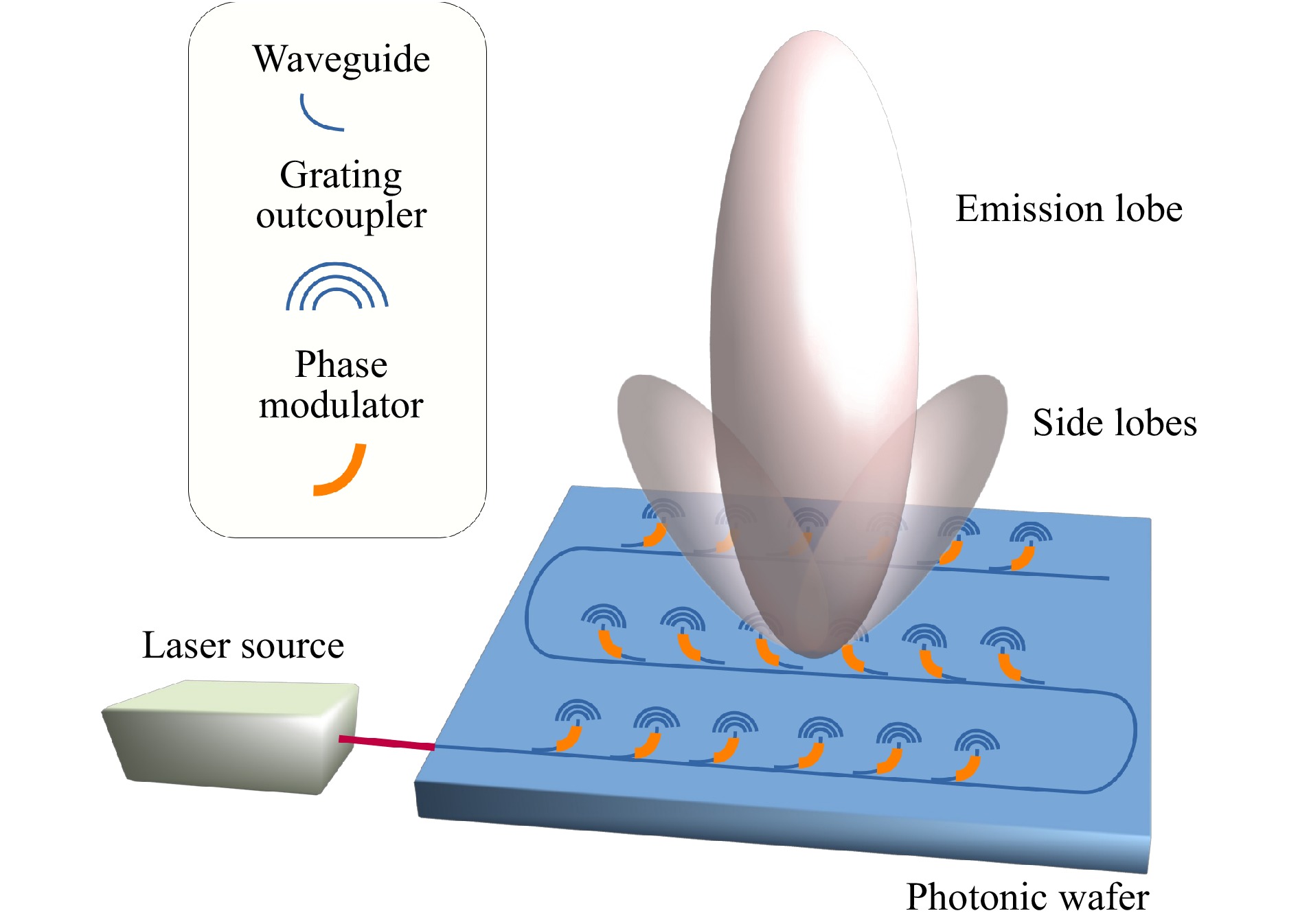
Fig. 6 Schematic of a photonic integrated circuit optical phased array. A single coherent laser source is directed inside a waveguide, from which light is extracted by multiple grating couplers (acting as light antennae). The phase at each antenna can be tuned using a phase modulator to create a hologram.
The advantage of PIC phased array technology is the very high frequency at which the phase can be modulated. Electro-optic modulators can reach one hundred GHz146, 147. This inherently elevates the data rate to the
$ 10^{10} $ b/s order. Using an array with$ 300\;\times \;300 $ antennae would achieve the$ 10^{15} $ b/s required for a holographic display. As we will discuss, the present difficulties of photonic phased arrays are the wafer material, the gaps between antennae, and the phase accuracy between antennae.The preferred material for PIC is silicon, which does not transmit visible light. Other materials with better transmission in the visible wavelengths should be used for display purposes. Silicon nitride or silica platforms have already been explored for optical phased arrays in the literature, but remain in their experimental phase145, 146, 148, 149.
Compared to MEMS and LCoS that have a fill factor above 90%, the fill factor of the phased array is fairly low, at approximately 25%. The fill factor affects the diffraction efficiency owing to the presence of side-lobe emissions that cannot be canceled if the antennae are too far apart. This separation is due to the limited turn radius of the waveguide and the required separation between waveguide elements to avoid cross-coupling150. Both factors, turn radius and waveguide separation, are dictated by the difference in the index of refraction between the inside and outside of the waveguide. A larger index difference would allow for a larger fill factor.
The phase control of the pixels is better in LCoS than in both MEMS and phased arrays. The LCoS phase is analog and proportional to the applied voltage and is therefore uniform across pixels. In contrast, current MEMS micro-mirror levels are discrete and limited to 4 bits, and exhibit some nonlinearity134. For phased arrays, the phase control is analog and accurate, but has to be characterized for each element individually owing to manufacturing inconsistencies145.
In summary, none of the current SLM technologies is sufficiently mature to meet all the criteria required for a large-size, high-definition holographic 3D display. This should not overshadow the considerable progress that has been made over the past years, bringing the end goal ever closer.
-
Holography is still considered as the ultimate technology that will enable rendering of all the optical cues needed for the human visual system to see projected images in 3D. All other technologies, such as (auto) stereoscopy, light-field, or volumetric displays suffer from trade-offs that limit 3D rendering. Nonetheless, these technologies will likely prove to be stepping stones leading to better visual comfort until holographic displays are achieved.
Some of the doors that were preventing holographic television from being made possible only a few years ago have already been unlocked. The fast computation of 3D holograms to properly control occlusions and parallax is now within reach as is a solution to the problem of data transmission. The exact architecture of the network (thick or lean client) is unclear, but higher compression rates and ever faster telecommunication infrastructures supporting the Internet mobile communications make streaming the data for a holographic television feasible, if not yet accessible.
However, some challenges remain to be solved. The two main obstacles at the time this manuscript was written are the computation of photorealistic 3D holograms in a reasonable amount of time, and a suitable electronic device for the reproduction of large holographic 3D images with high resolution.
For the pioneers of holography, Gabor, Leith, Upatnieks, and Denisyuk, the challenge of controlling diffractive pixels could only have been a physicist’s dream. This dream has now been transformed into an engineering nightmare, as devices that can project holographic images exist, but scaling the format to project large images can be surprisingly difficult. Computational time becomes prohibitive, and controlling trillions of pixels currently requires an extremely large number of graphic cards.
Nonetheless, the difficulty of projecting large holograms will soon no longer be in the engineering realm, but will rather transform into an economic problem. Initially, the hardware needed to build a holographic television will be too expensive to be successfully commercialized as a television set. Once price becomes affordable, the holographic television will face the same hurdle that each new media is bumping into, which is the availability of correctly formatted content. There is no advantage in owning a holographic television if creators are still producing 2D movies exclusively. For these reasons, it is likely that the market will move incrementally, starting with HPO multiview, expanding to light-field and full parallax, and finally reaching holography.
To achieve this dream of the perfect display, we should remember that the bit rate progression reported in Fig. 1 is not an immovable fact of nature. It is a testament to human ingenuity and hard work. This exponential growth can be influenced in one way or another by our own actions. Ultimately, where there is a will, there is a way, and the desire for a truly immersive visual experience is ingrained in human nature. It is this desire that will make the holographic television a reality sooner than later.


 DownLoad: