-
Electronic skin (e-skin) is an emerging bionic tactile sensor for healthcare management1–3, artificial throats4,5, prosthetic limbs6, mental fatigue recognition7, human–machine interactions8, etc. To date, most studies have focused on improving the performance of e-skins in terms of electrical signal output9–12. However, electrical outputs may be insufficient for addressing emergencies owing to indirect information transfer. Conferring e-skins with a visualized optical response is highly anticipated in interactive electronics, as it offers a more intuitive and enriched interaction13,14. Inspired by chameleon/lizard skins15,16, stretchable photonic crystals (PCs) made of nanoparticles (NPs) and elastomers have been extensively explored as optical strain sensors17,18. A stretchable PC exhibits color-switching upon being subjected to mechanical stimuli by altering the nanocrystal lattices in its ordered periodic structures19,20. As structural colors are unfading and visually readable without power sources, stretchable PCs have recently been integrated with e-skins to create photonic-electronic skin (PE-skin) to provide dual-signal sensing for high-level intelligence21–24.
High mechanochromic (MC) and mechanoelectrical (ME) sensitivities along with a wide working range are generally required to achieve desirable visual interactions and accurate detection. According to Bragg’s law, the structural color of a PC is significantly affected by its interparticle distance (DIP). A non-close-packed PC with a large DIP leaves a large room for deformation, which facilitates the achievement of a high MC range or sensitivity (defined as Δλ/ε, where λ and ε are the wavelength and strain, respectively)25. Etching close-packed NPs with chemical agents can produce non-close-packed PCs22, but this strategy inevitably involves hazardous chemicals (e.g., hydrofluoric acid) and repeated cleaning to remove the etching agent from substrates (e.g., hydrogel). The swelling of polymers using solvents is a simpler method for fabricating non-close-packed NP arrays21; however, this method induces only a small DIP (< 50 nm), resulting in a narrow color shift (Δλ < 200 nm). Another similar strategy is the self-assembly of NPs with a hydrogel precursor, in which the interparticle spacing is caused by a sufficient charge or solvation layer. However, the yielded DIP remained insufficiently high (< 100 nm). In short, three main strategies, swelling, self-assembly, and chemical etching, have been developed to fabricate stretchable non-close-packed PCs for PE-skins13,21,22. However, the swelling method fails to generate an NP array with a large spacing, and the latter strategies suffer from poor performance (small Δλ, low MC sensitivities), limited stability (hydrogel dying), and/or cumbersome processing involving strong acids, time-consuming procedures, and low temperatures.
In addition to MC sensing, the electrical sensing of capacitance, photocurrent, and resistance is usually integrated with PC layers. These electrical components are nearly all based on hydrogels containing conductive fillers, such as ionic liquids, reduced graphene oxide, and carbon nanotubes22,26. However, such conductive hydrogels exhibit low ME sensitivities (gauge factor, GF < 5), rendering them ineffective for detecting subtle physiological signals, such as pulses (e.g., ε < 2%)27. Additionally, the PC layers cannot output visually perceivable color changes in this case. Consequently, very few reported PE-skins have successfully demonstrated the detection of full-range human motions. Developing dual-function PE-skins with high electrical and optical sensitivities and wide sensing ranges in a straightforward manner remains highly challenging and desirable.
In this study, a novel PE-skin with high MC and ME sensitivities coupled with a wide working range was developed by integrating an NP-based PC with a conductive bilayer nanocomposite within an adhesive polydimethylsiloxane (A-PDMS) matrix. Mimicking a panther chameleon’s iridophore, the PC layer was devised to consist of ordered, non-close-packed NPs with a large in-plane DIP, fabricated using a combination of “Marangoni self-assembly,” “plasma etching,” and “A-PDMS transfer” (MPT). The MPT method offers advantages, such as fast assembly (<10 min), eco-friendliness, simplicity, and multimonolayer patterning ability, while also endowing the PC with a distinct structure of in-plane-spaced, interplane-packed NP arrays. The PC exhibited a highly sensitive, wide red-shift response through in-plane stretching, which was different from previous blue-shift PCs induced by normal Poisson compression. To the best of our knowledge, this is the first report of a red-shift, tensile-responsive NP-based PC that mirrors the MC behavior of a chameleon’s iridophore. For the ME component, the bilayer of MXene/silver nanowire (AgNW)-PDMS is inspired by the microcracked structure of spider slit organs28. The crackable MXene layer imparts the PE-skin with ultrahigh sensitivity and vivid colors through light absorption, whereas the AgNW network beneath provides large stretchability. Finally, we demonstrate the detection of full-range human motions (e.g., from weak pulses to large joint flexion) using the PE-skin.
-
The PE-skin comprised a PC layer composed of polystyrene NPs and a piezoresistive film composed of MXene and AgNWs (Fig. 1a). The PC structure was fabricated using the MPT method. The fabrication process began with the solution deposition of polystyrene NPs on hydrophilic glass. The NP distribution on the glass was inhomogeneous, resulting in a nonuniform structural color (Fig. S1). To achieve a uniform structural color, the glass substrate was immersed in water, allowing the NPs to float because of the hydrophobic surface of polystyrene and the high surface tension of water (Fig. 1b). At this stage, the NPs floating on the water were loosely packed and disorderly distributed. Subsequently, an amphipathic surfactant, dodecyl sodium sulfate (SDS), was dripped into the water to facilitate the formation of a compact, periodic NP array (Fig. 1c). The hydrophilic end of the SDS molecules faced the water, whereas the hydrophobic end faced away, forming an SDS monolayer that lowered the local surface tension and created a surface tension gradient near the droplet29. This induced a Marangoni flow from the dripping position toward the boundary, which dragged the floating NPs. As the SDS layer spread out, the polystyrene NPs moved until they reached the adjacent NPs, forming a close-packed periodic monolayer of NPs.
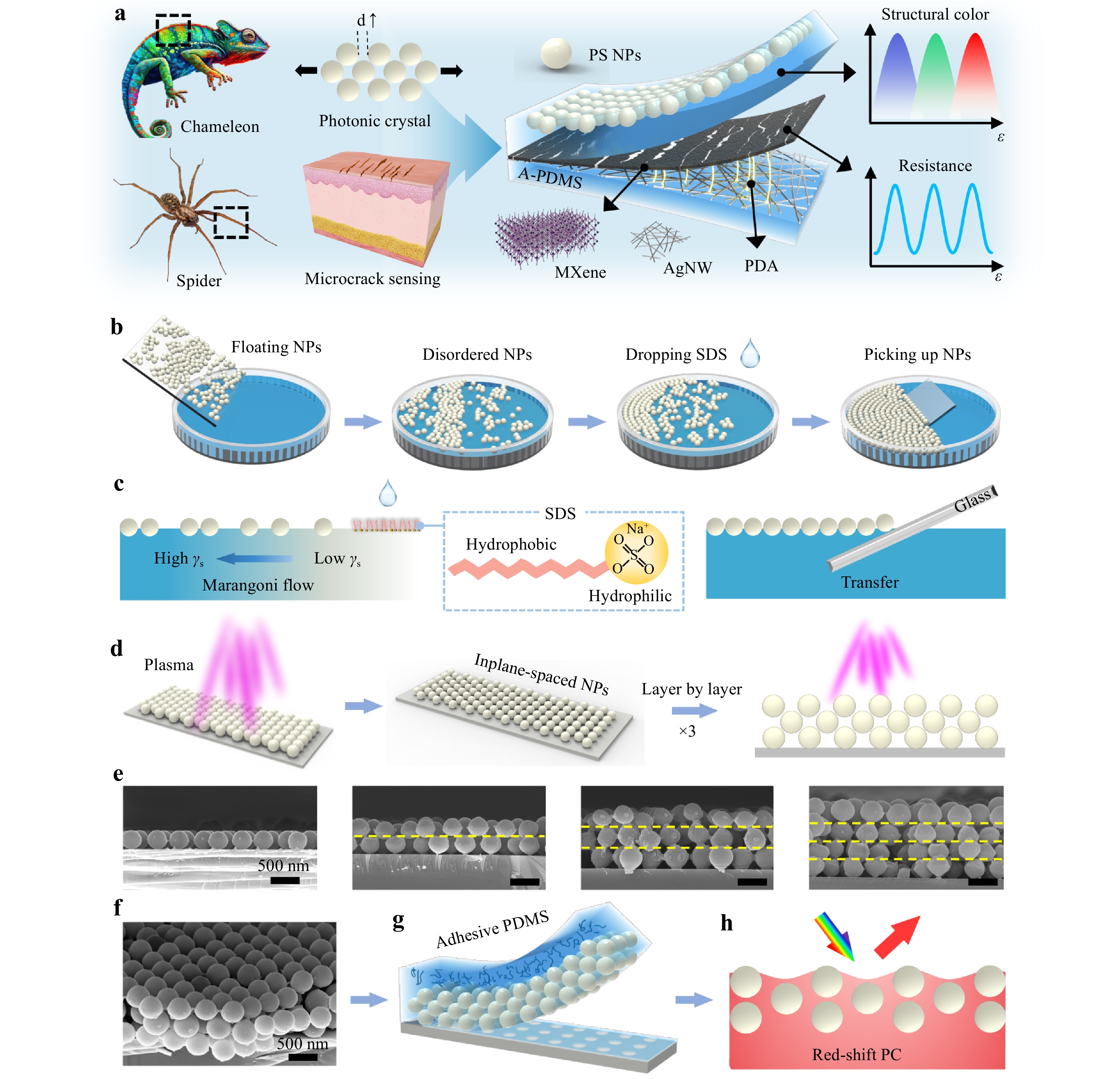
Fig. 1 Scheme of the PE-skin. a Schematic of the bioinspired dual-function PE-skin b-c Fabrication procedure for a closely packed NP array with Marangoni self-assembly. d Fabrication procedure for the array via plasma etching and layer-by-layer assembly. e Scanning electron microscopy (SEM) images of single-layer PC and multilayer NP PCs. f SEM image of the trilayered NP PC. g Transfer of trilayered PC to adhesive PDMS. h Schematic of the stretched PC showing its structural color.
A closely packed NP monolayer was transferred onto glass to construct a stretchable PC film. The transferred monolayer retained a highly ordered close-packed NP array structure over a large area (Fig. S2). However, non-close-packed structures with a large interparticle spacing are generally required to achieve large deformations and abundant color changes during contraction and stretching25. Therefore, air plasma was used to etch the polystyrene NPs and increase the interparticle spacing (Fig. 1d). Moreover, plasma treatment can generate oxygen-containing groups on polystyrene NPs, improving their adhesion to glass (Fig. S3), which allowed a second immersion of the NP monolayer/glass without detachment and enabled the assembly of a second NP layer (Video S1). Plasma treatment can also enhance the adhesion between the two NP layers, enabling the assembly of additional monolayers. Repeating these procedures yielded an in-plane-spaced, interplane-packed multilayer NP array (Fig. 1d-e and Fig. S4). Each layer in the assembled device maintained an ordered structure and a well-defined interface between the adjacent layers (Fig. S5). Moreover, the upper layer effectively shielded the sublayer from plasma etching, ensuring only minor differences in NP size across the layers when subjected to the same plasma treatment duration (Fig. S5). Finally, the A-PDMS prepolymer with strong adhesion was cast onto the multilayers of the non-close-packed NPs, enabling the complete transfer of the NPs into A-PDMS, resulting in a stretchable PC with vibrant structural colors (Fig. 1f-g).
A conductive MXene/AgNW-PDMS layer was fabricated using vacuum filtration (Fig. S6). The AgNW suspension was then filtered through a porous polytetrafluoroethylene (PTFE) membrane to obtain a uniform film. The A-PDMS liquid was cast and cured on the film, followed by a peeling-off step to obtain the embedded AgNW-PDMS film. After the plasma treatment, the AgNW-PDMS film was first modified with polydopamine (PDA) to enhance the interface adhesion and then coated with MXene nanosheets. The MXene/AgNW-PDMS film was then attached to the back of the PC-PDMS layer to complete the fabrication of the PE-skin using A-PDMS liquid as a binder. The MXene/AgNW layer served two primary functions: electrical strain sensing and acting as a black matrix to prevent the background colors from interfering with the structural colors (Fig. S7). Upon stretching, the MXene/AgNW membrane formed microcracks to achieve ultrahigh electrical sensitivity, whereas the PC layer visualized the external strains through abundant and vivid structural colors (Video S2).
-
PDMS was modified with a fluorosurfactant (Zonyl FS-300) to increase its adhesive strength for the fabrication of stretchable NP-based PC films (Fig. 2a). The raw PDMS with a Young’s modulus of approximately 1.05 MPa (Fig. S8) did not produce an adequate grip force to overcome the van der Waals forces between the polystyrene NPs and glass, which resulted in transfer failure (Fig. 2c)30. Consequently, the surfactant Zonyl FS-300 was added to the PDMS prepolymer to change the crosslinking process (A-PDMS). During the curing of Sylgard 184, crosslinking between the vinyl functional base and the hydrosilyl functional crosslinker is catalyzed by a platinum complex. The ethylene glycol group of the surfactant chemically conjugates with Pt31, thereby reducing the diffusion of Pt or depleting it to produce heterogeneously crosslinked PDMS. A-PDMS exhibited improved adhesion strength and elongation at break (Fig. 2b), and a reduced Young’s modulus of 208 kPa (Fig. S8a). The modification slightly reduced the Poisson’s ratio (Fig. S9) while increasing the stretchability of PDMS from approximately 166% to 313% (Fig. S8), potentially owing to the presence of locally crosslinked or loosely crosslinked domains.
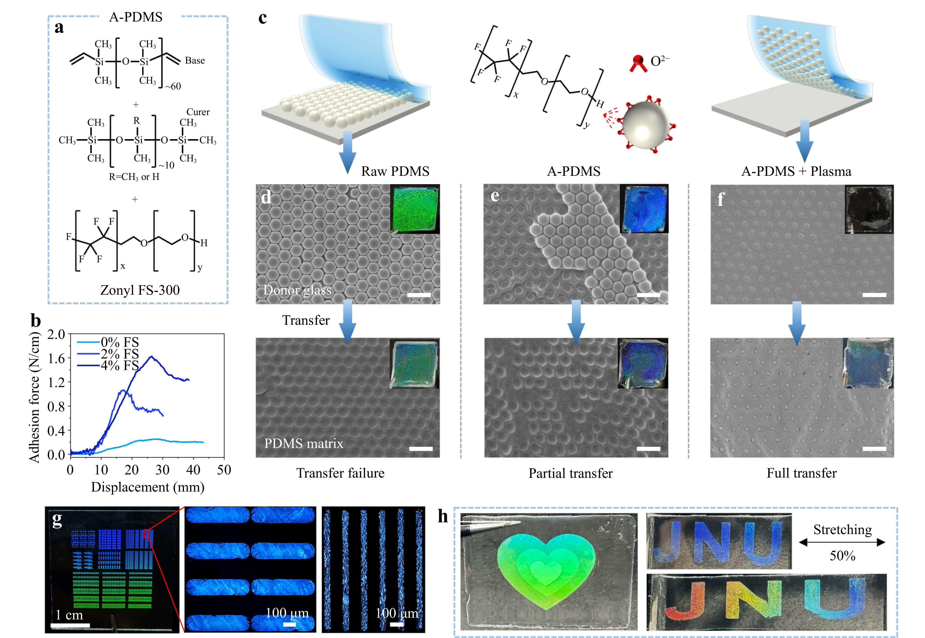
Fig. 2 Transfer of the PCC with A-PDMS. a Molecular structures of the base, curer, and surfactant of A-PDMS. b Stress–strain curves of PDMS films with different concentrations of the surfactant. c Schematic, d-f SEM images and photographs (insets) of the PCC transfer using raw PDMS and A-PDMS. g Photograph and optical microscopy (OM) images of the patterned PCC on glass, scale bar: 100 μm. h Photographs of the patterned multimonolayer PCC in A-PDMS.
Fig. 2c shows the schematics and experimental results of NP transfer using raw PDMS and A-PDMS. The casting of liquid PDMS does not affect the periodic structure of the polystyrene colloidal crystal (PCC) but slightly increases the DIP (Fig. 2d-f and Fig. S10). The raw PDMS matrix failed to transfer the PCC, leaving the NPs on the glass (Fig. 2d). The raw PDMS layer replicated the PCC nanostructure, but exhibited poor chromaticity. This transfer failure is attributed to the weak adhesion between raw PDMS and polystyrene NPs owing to the low surface energy (16 mJ m−2) of PDMS32. To enable an efficient PCC transfer, A-PDMS with enhanced adhesion was used as the transfer carrier. Fig. 2b indicates that the addition of 4 wt.% surfactant enhanced the adhesion of PDMS from 0.25 to 1.63 N cm−1. Nevertheless, some polystyrene NPs remained on the glass after the transfer (i.e., partial transfer, Fig. 2e). After the plasma treatment, the PCC could be fully transferred onto A-PDMS (Fig. 2f). This is because the plasma treatment can produce hydroxyl and carboxyl groups on the surface of the polystyrene NPs (Fig. S3), which can chemically conjugate with the ethylene glycol group of the surfactant to increase the interaction forces between the NPs and A-PDMS33. Additionally, high-energy species in the plasma can break the molecular chains of the polystyrene NPs, creating microscopic crater structures (Fig. S11)34, which further enhance the interface adhesion.
The above MPT method for fabricating stretchable PCs has several distinct advantages over conventional approaches, such as polymer swelling, chemical etching, and hydrogel self-assembly. First, the MPT method requires less than 20 min to form a non-close-packed PCC, whereas conventional methods typically require hours to weeks to complete the colloidal crystal assembly (Fig. S12). In addition, the MPT method requires only water and SDS for interfacial assembly at room temperature, making it an easy process. Another advantage of the MPT method is the facile patternability of the colloidal crystals. High-resolution and large-area patterns of the PCC can be readily achieved using a stencil mask during the air-water assembly (Fig. S4b). Fig. 2g shows the OM images of the sharp, well-defined PCC patterns with a size of 30×30 mm2, a minimum spacing of 10 μm, and a linewidth of 100 μm. Moreover, a simple layer-by-layer assembly can produce a multilayered PC pattern in which each monolayer can be customized (left image in Fig. 2h). However, this multimonolayer patterning is difficult to achieve using conventional methods. It is anticipated that multimonolayered patterned PCs have significant potential for antiforgery applications. The patterned PC can be easily transferred onto A-PDMS to form a stretchable PC (Fig. 2h).
-
An advantage of the MPT method is that the DIP can be easily adjusted by varying the plasma-etching duration. As shown in Fig. 3a, b, the average diameter of the polystyrene NPs decreased from 503.9 ± 15 to 271.5 ± 17 nm after 4 min of plasma etching. Consequently, the DIP could be precisely tailored within the range of 0 to 271.3 nm, which is significantly broader than that of NPs produced by swelling, etching, and self-assembly (mostly DIP < 100 nm, see Table S1)13,21,22. Fig. 3b shows that 50% of the DIP values are uniformly distributed between 100 and 200 nm, whereas 25% exceed 200 nm, with an average value of 225 nm. This value is comparable to the mean spacing (240 nm) of guanine crystals in the S-iridophores of the chameleon F. pardalis15. The large DIP (4-min plasma treatment, P4) endowed the PE-skin with wide color-switching from 442 to 661 nm (Δλ = 219 nm) under a strain range of -15%–70%, achieving an MC sensitivity of 2.5 nm %−1. By contrast, the close-packed NP array (P0) exhibited a narrower switching range (478 to 638 nm, Δλ = 160 nm) in a smaller strain range of 51% (Fig. 3e-f). The CIE chromaticity (Fig. 3j) and corresponding photographs (Fig. 3c-d) show that the non-close-packed PC (P4) exhibited higher color saturation than the close-packed PC (P0). The color gamut of the P4 film was 63.1% DCI-P3, which is more than four times that of the P0 sample (Fig. S13-S14).
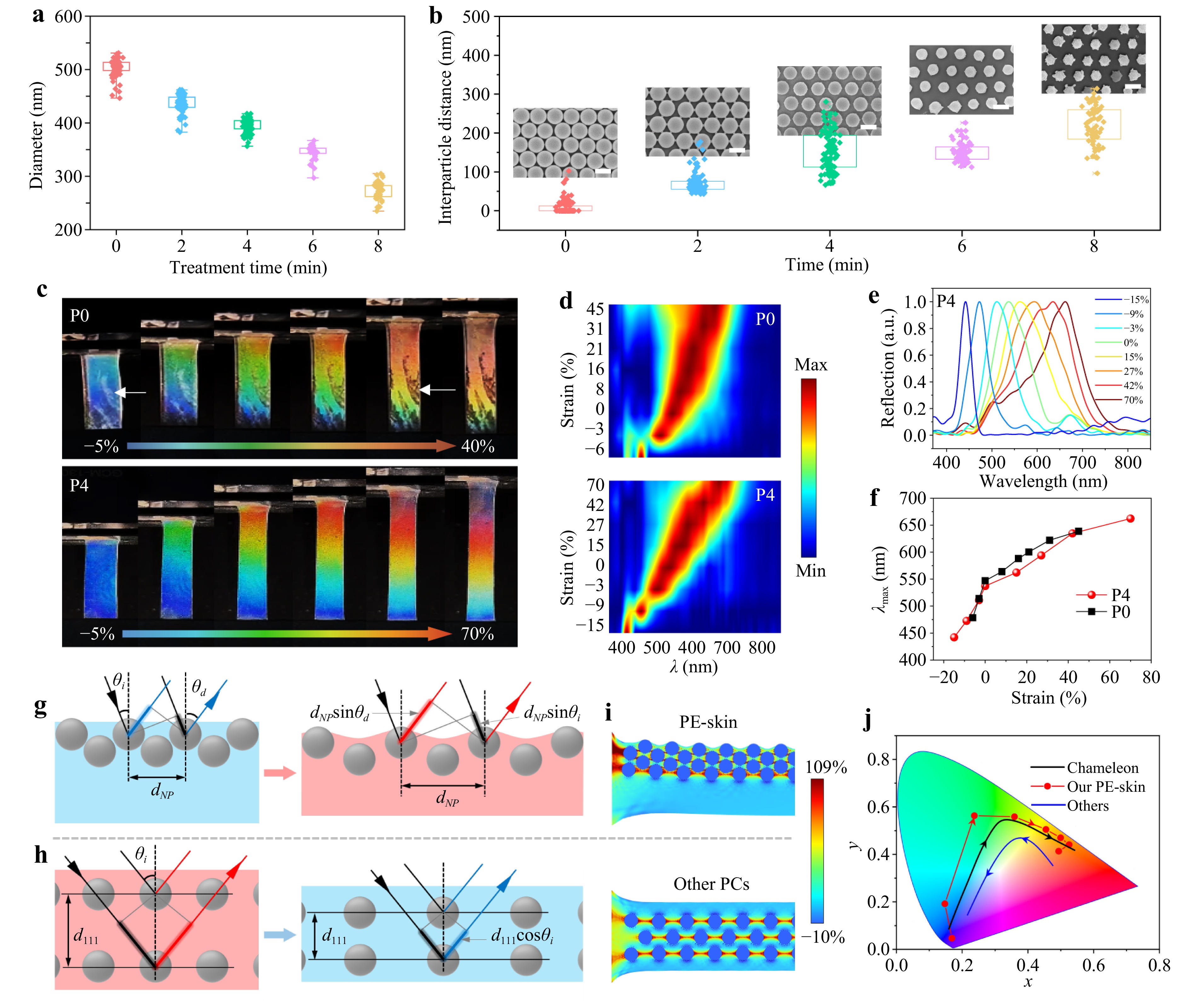
Fig. 3 Optical performance and mechanochromic mechanism of the PE-skin. Distributions of a NP diameter and b interparticle spacing with different times of plasma treatment. The insets are the SEM images of the etched NPs. c Photographs, d color-filled contour maps, e reflectance spectra, and f peak wavelength shift of the P0 (without etching) and P4 (4-min etching) devices under different strains. g-h Schematics of the color-switching mechanisms upon external strains for our PC and other PC devices, respectively. i Mechanical simulation of the PC in the PE-skin and other PC. j CIE chromaticity diagram showing the red-shift responses of the PE-skin and a panther chameleon (reproduced from the reference15) and the blue-shift response of other PCs during tensile stretching or skin expansion.
Notably, the PE-skin underwent a continuous red-shift from violet to dark red under uniaxial tensile strain (Video S2). To the best of our knowledge, this is the first report on the red-shift MC behavior in stretchable NP-based PC strain sensors (Table S1-S2). As shown in Fig. S15, all previously reported NP-based PC strain sensors invariably display a blue-shift response behavior, which is attributed to typical normal Poisson compression that alters the spacing between crystal planes. Our PE-skin shares the same color-switching behavior as the panther chameleon. The PE-skin shifts from blue to red by increasing the in-plane NP spacing during stretching, whereas the chameleon displays a red shift by expanding the spacing between NP-like guanine crystals during excitation (cell expansion). Therefore, the MC trajectory of our PE-skin closely resembles that of the panther chameleon (Fig. 2j). The color gamut encompassed by the trajectory of the PE-skin exceeds that of the chameleon.
The exceptional red shift in the MC performance is attributed to the distinct PC structure. The crystal planes in the PE-skin were closely stacked (Fig. 1), whereas those in conventional PCs were more widely spaced. Second, our PC consists of a few layers (one to three) of crystal planes, which is significantly fewer than the tens of layers typically found in other PCs35. Under uniaxial stretching, our PC with closely stacked (111) planes experienced less normal compression than conventional PCs (Fig. S16). Mechanical simulations revealed that the spacing change Δd111 between the adjacent crystal planes of our PC was only 38.5% of that observed in the other PCs in the strain range of 0%–50% (Fig. S16). Therefore, the MC responses are dominated by two-dimensional (2D) Bragg diffraction (Fig. S17 and Fig. 3g), whereas those in conventional PCs are primarily governed by three-dimensional (3D) Bragg diffraction (Fig. 3h).
Furthermore, the upper NP array in the PE-skin was embedded into the PDMS surface and protruded slightly (tens of nanometers in height, Fig. S18). Under tensile strain, a sinusoidal submicron structure was formed on the surface of our PC owing to the mismatch in Young’s moduli between polystyrene and A-PDMS (Fig. 3i). The submicron-structured surface further enhanced light diffraction, producing more vivid colors (Fig. S19). Based on the optical differences indicated in Fig. 3g-h, 2D Bragg diffraction in the PE-skin and 3D Bragg diffraction can be characterized by Eq. 1, 3, respectively.
$$ m\lambda ={d}_{NP}(\mathrm{s}\mathrm{i}\mathrm{n}{\theta }_{i}+sin{\theta }_{d}) $$ (1) $$ {d}_{NP}={d}_{\mathrm{N}\mathrm{P}}^{0}(1+{\varepsilon }_{x}) $$ (2) $$ m\lambda ={2d}_{111}{({n}_{eff}^{2}-{sin}^{2}{\theta }_{i})}^{1/2} $$ (3) $$ {d}_{111}={d}_{111}^{0}(1-\nu {\varepsilon }_{x}) $$ (4) where m is a positive integer, and $ {\theta }_{i} $ and $ {\theta }_{d} $ are the angles of incidence and diffraction, respectively. $ {d}_{NP} $ is the spacing between NPs in a (111) plane, and $ {d}_{\mathrm{N}\mathrm{P}}^{0} $ is the spacing at the tensile strain $ {\varepsilon }_{x}=0 $. d111 is the spacing between the (111) planes, and $ {d}_{111}^{0} $ is the spacing at $ {\varepsilon }_{x}=0 $. neff is the effective refractive index of the PC. ν is the Poisson’s ratio of PDMS (≈0.5). According to equations (1)–(4), increasing the tensile strain leads to an increase in $ {d}_{NP} $ for the PE-skin, producing a red-shift response, whereas decreasing d111 for conventional NP-based PCs results in a blue-shift response. Equation (1) further indicates that structural color is angle-dependent. The red-shift response behavior was observed at different incident light angles (Fig. S20). The diffracted wavelength increased with the viewing or light incident angle, which contrasts with the angle-independent structural colors observed in lizards (Fig. S21).
Owing to the relative chemical and thermal stabilities of polystyrene and PDMS, the PE-skin exhibited good MC, thermal, and storage stabilities. As the elongation at break (> 300%) of PDMS far exceeds the working range (70%) and PDMS exhibits high fatigue, our PC has excellent color-switching stability during a 1000-cycle stretch–release test (Fig. S22). Additionally, no noticeable change in the structural colors can be observed by the naked eye when the PC is annealed at temperatures ranging from 30 to 90 °C (Fig. S23). The PC also retained vivid colors even after long-term storage in air, high humidity, and oil (Fig. S24).
-
As the PC layer, with an MC sensitivity of 2.57 nm %−1, is inadequate for visually detecting subtle physiological signals, such as wrist pulses (ε < 1%28), a conductive MXene/AgNW bilayer with a high GF was developed to detect small strains via electrical signals. The material properties and membrane structure are key parameters that affect the ME performance. As shown in Fig. 4a, the AgNW network shows desirable stretchability with a low sensitivity of GF =16.7 (GF = ΔR/R0/ε, where ΔR/R0 is the relative resistance change, and ε is the tensile strain). Such a low GF is ineffective for the accurate detection of subtle skin deformations, such as wrist pulses (a GF of 20–200 is required27,36). The MXene membrane coated onto PDMS has high sensitivity but operates within a narrow working range (ε < 1%) owing to the small elongation at break of MXene (4.5%)37. Moreover, neither simply blending AgNWs with MXene (MXene&AgNW), nor using a bilayered structure (MXene/AgNW)38 and a sandwich structure (AgNW/MXene/AgNW) can simultaneously achieve high sensitivity and large stretchability (Fig. 4b).
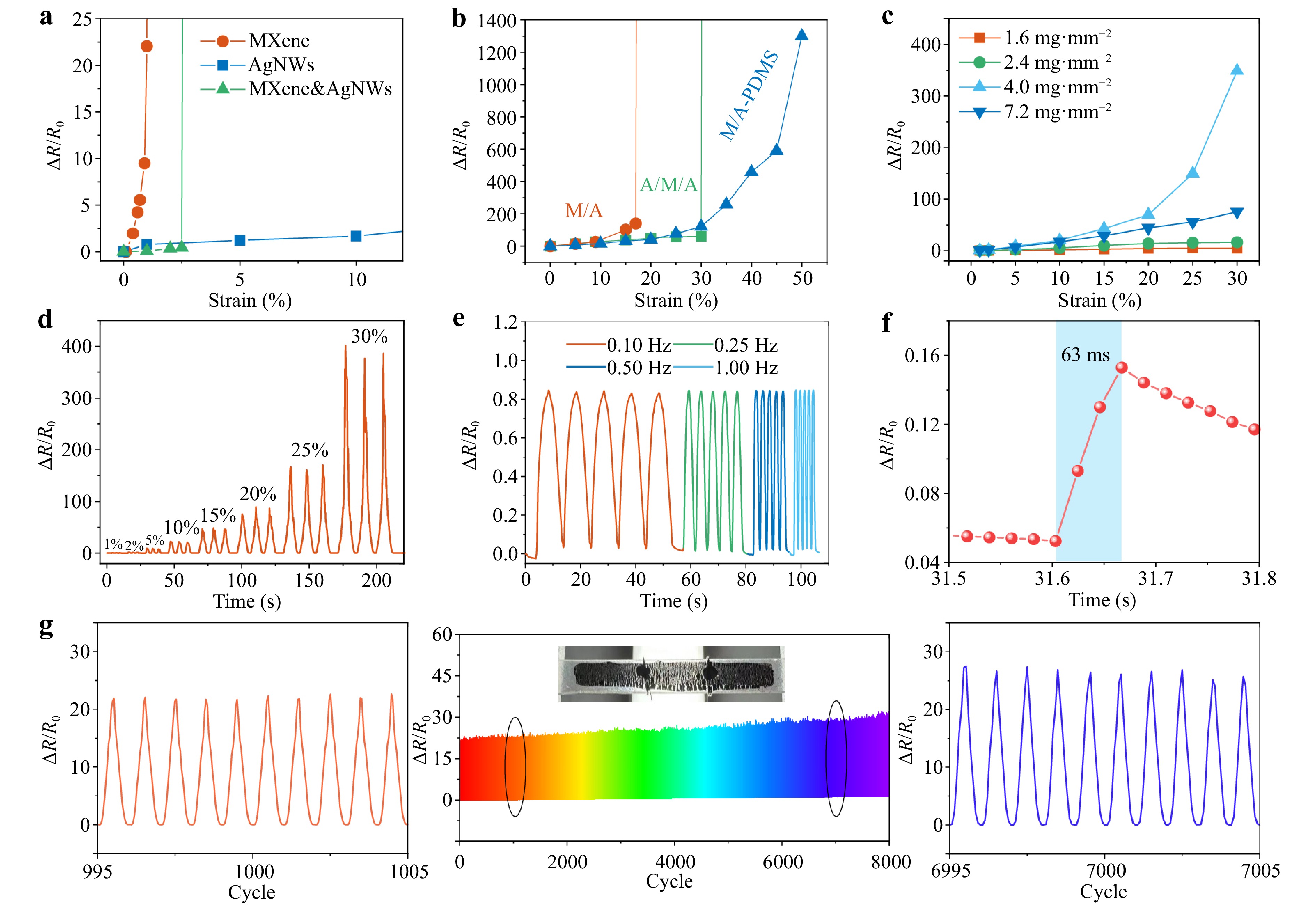
Fig. 4 Mechanoelectrical performance of the nanomaterial films and PE-skin. a ΔR/R0 variation versus strain of the MXene, AgNW, and MXene&AgNW films on PDMS. b ΔR/R0 variation versus strain of the MXene/AgNW/PDMS (MA), AgNW/MXene/AgNW/PDMS (A/M/A), and MXene/AgNW-PDMS sensors. c ΔR/R0 variation versus strain of the MXene/AgNW-PDMS sensors with different AgNW concentrations. d ΔR/R0 curve of the optimized sensor in the strain range 0%–30%. e ΔR/R0 curves at different stretching frequencies under 5% strain. f One-cycle response at 1% strain. g Cyclic response at 10% strain for 8000 cycles.
Unlike conventional surface coatings or layered structures39, we embedded AgNWs into A-PDMS and subsequently coated it with an MXene layer to achieve both high GF and high stretchability. Upon stretching, the embedded AgNWs provided stable conductive pathways under a large strain of 50%, whereas the upper layer of MXene achieved high sensitivity (GF up to 2600) through crack formation. The sensitivity of the MXene/AgNW-PDMS layer first increased and then decreased with increasing AgNW concentration (Fig. 4c). The optimal concentration was approximately 4.0 mg mm−2, which was used for device fabrication. Fig. 4d shows the stepwise ΔR/R0 of the strain sensor within 30% strain, in which the average GF was approximately 228.1 within 10% strain, and the highest GF was 1339.6 at 30% strain. Fig. 4e shows the electrical response of the MXene/AgNW sensor at different stretching frequencies under 5% strain. The peak-to-valley amplitude of ΔR/R0 remained nearly constant in the frequency range of 0.1–1 Hz, indicating no frequency effect in the ME response. By applying rapid stretching, the response time was measured to be 63 ms (Fig. 4f), which is sufficient for the real-time monitoring of human motion. The sensor was also subjected to cyclic stretch–release tests with the maximum strains of 10% (Fig. 4g) and 50% (Fig. S25). In the 10% strain test, the variation in ΔR/R0 between cycles 995 and 1005 and cycles 6995 and 7005 did not exceed 20%. The cyclic test at 50% strain resulted in a high variation in ΔR/R0 with a standard deviation of 114.3, and the cyclic stability recovered at small strains (20%) with a standard deviation of 3.2 (Fig. S25). The sensing layer also showed tiny variations in resistance in the range of 30 to 90 °C (Fig. S26). These results demonstrate the good ME and thermal stability of MXene/AgNW-PDMS. The good stability can be ascribed to the interlayer PDA, which firmly glued MXene to the AgNW-PDMS. The amines and groups of PDA formed coordination bonds and/or hydrogel bonds with both MXene and the AgNW-PDMS surface (Fig. S27e). The sensor without the PDA modification underwent noticeable deterioration during the 1000-cycle test (Fig. S27(a-d)). At strains exceeding 50%, much greater instability in ΔR/R0 was observed for the sensors. Nevertheless, a strain-sensing range of up to 50% covers most skin deformations (< 50% strain). Stretchability sensing can be improved by prestretching PDMS during the deposition of MXene, which requires further study.
The superior ME performance of the PE-skin can be attributed to the bilayer structure of the MXene/AgNWs, in which the coated MXene membrane induced high sensitivity, whereas the AgNWs embedded in A-PDMS provided stable percolative pathways under large strains (Fig. 5). Similar to other bilayered 2D/1D materials40, the MXene/AgNW sensing layer can be simplified as a parallel combination of the resistance RM of the MXene layer and the resistance RA of the AgNW layers. At a given nanomaterial density, the parallel structure results in a low initial resistance R0, which is conducive to achieving a high sensitivity (GF = ΔR/R0/ε)41. The coated MXene membrane, with a small elongation at break (4.5%), can form microcracks to further increase ME sensitivity37. As shown in Fig. 5a-d, the MXene layer displays short, crisscross microcracks at 10% strain and further forms long, penetrating cracks at higher elongation (30% strain). The penetrating cracks lead to substantial disconnections in the conductive layer, significantly increasing the GF42. The electrical disconnections were verified in the potential field distributions, which were simulated using a numerical method (Fig. S28). As shown in Fig. 5e-i, the voltage drop across the MXene film was negligible, indicating a low initial resistance. The gentle potential drop across the crisscross microcracks suggests that several conductive pathways were maintained at 10% strain (Fig. 5b, f). Under larger strains (Fig. 5c, g), the MXene membrane underwent transverse Poisson compression to connect the horizontal cracks and enlarge the vertical cracks43, resulting in a sharp voltage drop and local isolation domains (Fig. 5k). Considering the power law of cracks and the tunneling effect of the AgNWs embedded in A-PDMS, the MC response of MXene/AgNW-PDMS can be expressed as follows (see Supporting Note S1):
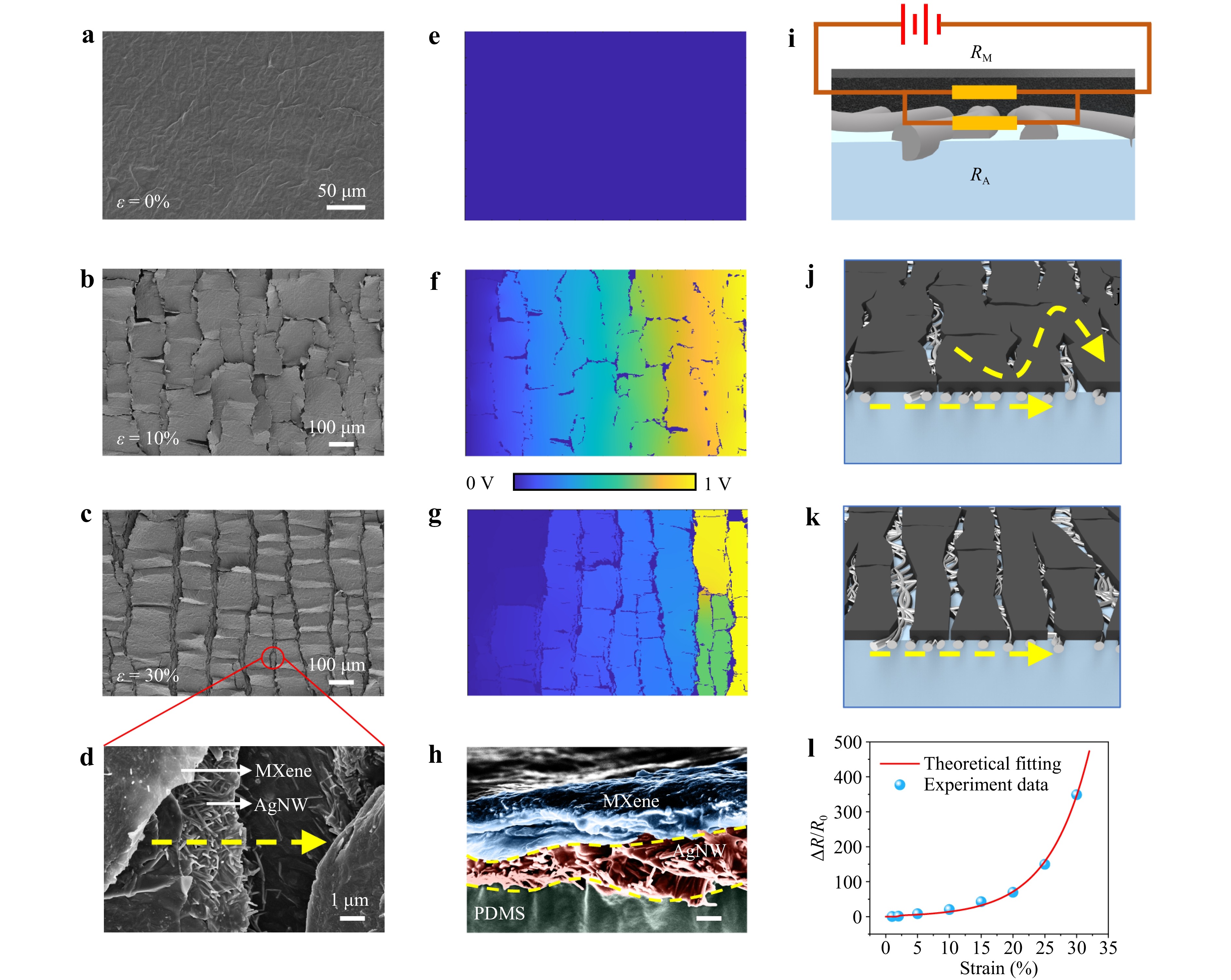
Fig. 5 Sensing mechanism of the MXene/AgNW-PDMS layer. a-d SEM images, e-g corresponding simulated electrical potential distributions, h Cross-sectional SEM image of MXene/AgNW-PDMS. and i-k equivalent circuit models of the MXene/AgNW layer under different strains. l ΔR/R0 versus strain of the PE-skin and theoretical fitting curve.
$$ \frac{\Delta R}{{R}_{0}}=\frac{\left({R}_{M0}/{R}_{A0}+1\right)\left(1+\varepsilon \right){e}^{a\varepsilon }}{{R}_{M0}/{R}_{A0}+(1+\varepsilon ){e}^{a\varepsilon }/(1+{b\varepsilon }^{n})}-1 $$ (5) where RA0 and RM0 are the initial resistances of the AgNW and MXene layers, respectively, b = $ {{(\varepsilon }_{0})}^{-n} $ is the constant parameter, and a is a constant related to the tunneling resistance of the AgNW networks. This equation was used to predict the change in the ΔR/R0 of the PE-skin under different strains and showed good agreement with the experimental results (Fig. 5l). Eq. 9 demonstrates that the sensitivity can be enhanced by lowering the initial resistance of the AgNWs (RA0), as shown in Fig. 4c. However, further lowering RA0 by increasing the loading of AgNWs led to a decrease in ΔR/R0. This deviation from Eq. 5 may suggest that the “contact and slippage” of NWs, rather than junction tunneling, is the dominant mechanism for the ME sensitivity in the high-density AgNW network.
-
Fig. 6a shows a comparison between the PE-skin and other dual-function e-skins in terms of ME sensitivity, MC sensitivity, and color-switching range, indicating the superior performance of the PE-skin among other sensors (Fig. 6a, Table S1). As skin deformation is generally estimated to be lower than 30%–50%44,45, the PE-skin with high ME (GF up to 2600) and MC sensitivities (2.57 nm %−1) coupled with a large strain-sensing range of ≥ 50% is well suited for the detection of full-range human motions. The conductive MXene/AgNW layer was used for the detection of subtle physiological motions, whereas joint motions with large strains could be detected by both the electrical and PC components (Fig. 6b). As shown in Fig. 6c, the color of the PC layer shifted gradually from violet-blue to green as the joints gradually bent (Fig. 6c), indicating a strain of approximately 15% for finger bending and a smaller strain for wrist bending. The PE-skin exhibited stepped color switching and resistance variation at different finger-bending angles (Fig. S29).
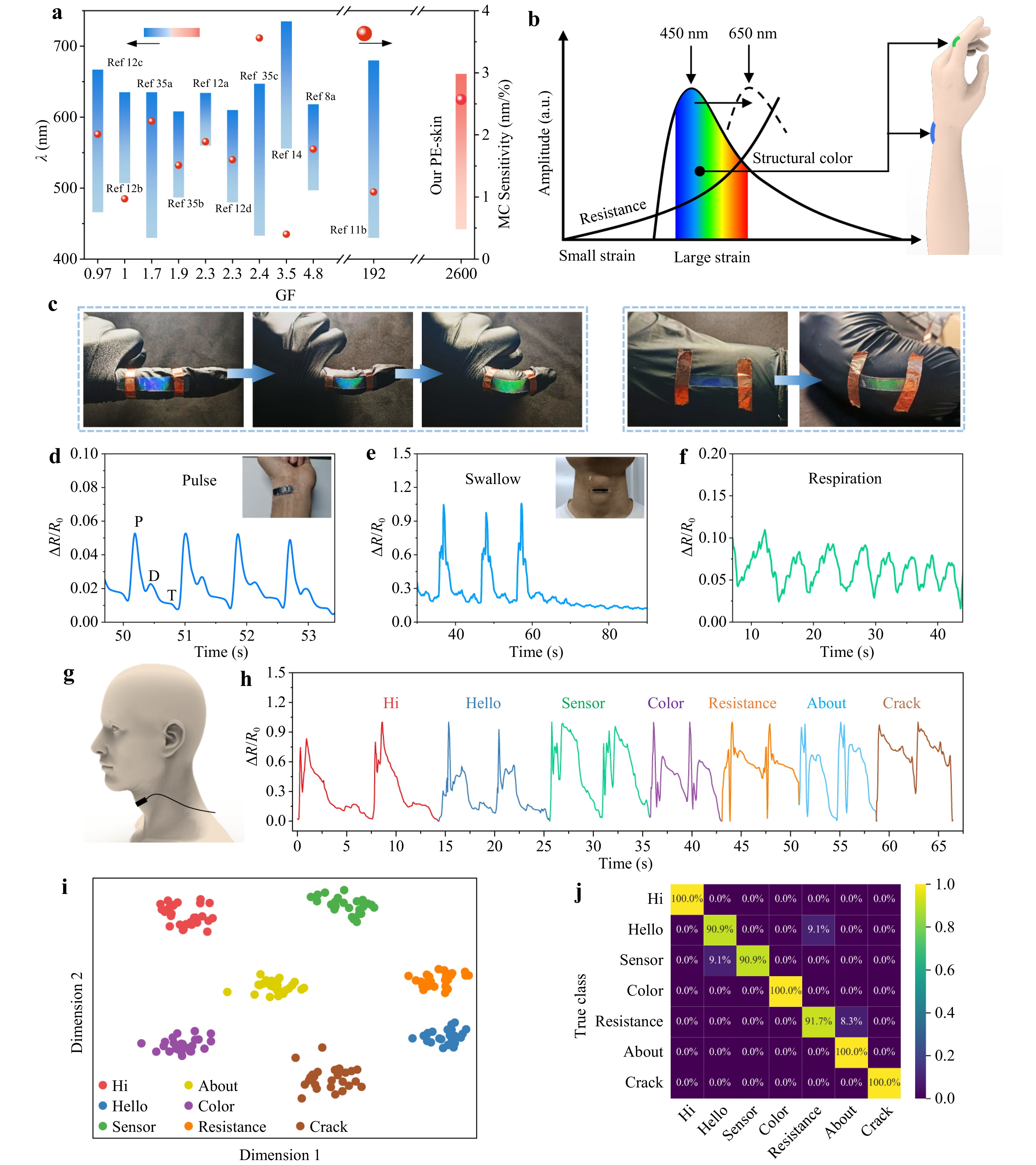
Fig. 6 Detection of full-range human motions using the PE-skin. a Performance comparison between the PE-skin and other dual-function sensors13,14,20-24,26,46-48. b Schematic of the detection of full-range human motions with the PE-skin. c Color shift of the PE-skin during finger and wrist bending. Electrical responses of the PE-skin to d wrist pulse, e swallow, and f respiration. g Schematic of voice detection and h experimental electrical responses to different pronunciations. i t-SNE projection of multichannel feature from 1D-ResConv. j Confusion matrix of 1D-ResConv on the test set.
The ability of the PE-skin to sense subtle physiological motions has been verified in the detection of wrist pulses, micro-expressions, breathing, swallowing, and speech. As shown in Fig. 6d, the electrical component with a high GF accurately detected weak wrist pulses with a dicrotic notch and three characteristic peaks: the impact wave (P), tidal wave (T), and relaxation wave (D). Important physiological parameters, such as the augmentation index, can be estimated from the peaks (Fig. S30). The PE-skin can also monitor microfacial expressions related to emotions, such as happiness, sadness, and anger (Fig. S31). When attached to the throat (Fig. 6g), the PE-skin outputs a main peak with two shoulder peaks corresponding to swallowing and weaker periodic waves from respiration (Fig. 6e, f). It can also detect pronunciation and exhibit distinct characteristic waveforms in response to different words (Fig. 6h). Complex speech recognition was realized using a single-channel PE-skin through a deep neural network algorithm, a 1D residual convolutional network (1D-ResConv, See Fig. S32 and Table S3).
1D-ResConv extracts multichannel features from the input signals and maps the sensing signals to points in a latent feature space. These points were visualized using t-distributed stochastic neighbor embedding (t-SNE), which revealed that the mapped points of each class were clustered with distinct centroids (Fig. 6i). The fully connected (FC) layer of 1D-ResConv classifies the signal features extracted from an earlier layer. Owing to the high sensitivity of the PE-skin and multichannel feature extraction, different classes of signals can be accurately classified using the FC layer. To fully leverage 1D-ResConv and improve the reliability of the verification results, 185 of the collected signals were randomly selected as the training set and the remaining 82 were used as the test set. The confusion matrix of the classification results is shown in Fig. 6j. Four of the seven words achieved a classification accuracy of 100%, whereas the remaining three words exceeded 90%, resulting in an average accuracy of 96.3%. Notably, only a few single-channel signals were used to construct a deep network with high accuracy. This demonstrates the potential of the PE-skin for automatic speech recognition and the diagnosis of articulation disorders.
-
We developed a dual-function PE-skin with high optical and electrical sensitivities across a wide working range. A non-close-packed NP PC with a large spacing was fabricated using the combined MPA method, which offers advantages, such as rapid assembly (as quick as 20 min), eco-friendliness, simplicity, and the ability to pattern multimonolayer PCs. The PC exhibits a distinctive red-shift MC response to in-plane strain, enabling a broad color-switching window (Δλ ≈ 219 nm) over a strain range of −15% to 70%, along with long-term stability. The underlying MXene/embedded AgNW layer formed a cracked conductive network, resulting in an ultrahigh electrical sensitivity with a GF of approximately 2600. This layer also serves as a light-absorbing component that enhances color saturation. This paper presented a novel assembly technique for stretchable red-shift PCs and introduced a bioinspired bilayer design for advanced artificial skins. However, a limitation of MPA assembly is the plasma etching process, which requires vacuum equipment, making it incompatible with continuous fabrication. Future investigations could explore the chemical dissolution of polystyrene to achieve larger interparticle distances and mask-free patterning of etching agents through solution-based processes (e.g., inkjet printing). Additionally, MXene/AgNW resistive strain sensors should be optimized for greater stretchability while maintaining high sensitivity so that both the resistive and optical sensing components in the PE-skin can effectively monitor large skin deformations.
-
Monodisperse polystyrene NPs with a mean diameter of 500 nm were purchased from Suzhou Smartynano Tech. AgNWs were obtained from Zhejiang Kechuang, Inc. Ti3C2Tx nanosheets were prepared by etching Ti3AlC2 powder (Foshan Xinxi Tech.) in an acidic solution of HCl/LiF49. The A-PDMS was prepared as follows: a PDMS prepolymer and curer (SYLGARD™ 184 silicone kit) were mixed at a weight ratio of 10:1. Subsequently, 2 wt.% Zonyl FS-300 (Dupont Company) was added to the PDMS liquid (A-PDMS), followed by thorough stirring and defoaming in a vacuum tank for 40 min.
-
Stretchable PC films were prepared using the MPT method. First, a polystyrene NP dispersion was spin-coated or drop-cast onto glass that had been cleaned with air plasma (Sunjune Plasma, VP-R5) to obtain a polystyrene NP array. To improve the order of the NP arrays, the NP/glass was slowly immersed in deionized water to allow the NPs to float. A few drops of a 4 wt.% SDS solution were added near the boundary of the NP array to form a close-packed NP array through a Marangoni flow. The close-packed NPs were slowly extracted using hydrophilic glass. After drying, the NP array was etched using air plasma to form a non-close-packed NP array. The multilayers of the array were obtained by repeating the above process, and three layers were used in this study. Finally, the A-PDMS prepolymer liquid was poured on the NP arrays and heated at 80 ℃ until curing. A stretchable PC was obtained by peeling the A-PDMS layer off.
-
An AgNW dispersion (10 mg mL−1) was magnetically stirred and diluted to 1 mg mL−1 in anhydrous ethanol. After ultrasonication for 2 min, the AgNW solution was vacuum filtered by using a PTFE membrane with a pore size of 0.22 μm39. After drying at room temperature (25 °C), the A-PDMS liquid was cast onto the AgNW film and allowed to stand for 15 min, followed by curing at 100 °C for 3 h. After peeling off the PDMS, an embedded AgNW elastic membrane was obtained and further treated with air plasma to improve the hydrophilicity and subsequently with polydopamine to enhance interface adhesion. Then, an MXene dispersion was drop-casted or spin-coated onto the AgNW/PDMS and dried at 100 ℃. Two silver wires of diameter 0.1 mm were attached to the two ends of the MXene/AgNW film. Finally, the PC layer was laminated with MXene/AgNW using A-PDMS liquid as a binder, forming the PE-skin after curing.
-
The microstructures of the PC, nanomaterials, and PE-skin were characterized using SEM (Carl Zeiss SUPRA 60). The PC micropatterns were observed using OM (Carl Zeiss Axio Scope A1). The reflection spectra of the PC at different tensile strains were measured using a homemade angular displacement platform equipped with a fiber-optic spectrometer (AvaSpec-ULS2048XL-EVO). Stretching–release tests of the PE-skin were conducted using a custom-built electrical displacement platform (Zolix, MAR 100-90), and the corresponding resistances were recorded using a digital source meter (Keithley 2611B).
-
This study was supported by the Basic and Applied Basic Research Foundation of Guangdong province (2024A1515030155, 2022A1515010272, 2024A1515012609, 2022A1515140055, 2023A1515011459, 2022A1515011671, 2022A1515140055), Natural Science Foundation of China (61904067, 62475101, 62175094, 62275109), Knowledge Innovation Program of Wuhan-Basi Research (2023020201010183), and Guangzhou-Jinan University Municipal and University Joint Funding Programs (202201020045).
Ultrasensitive bionic photonic-electronic skin with wide red-shift mechanochromic response
- Light: Advanced Manufacturing , Article number: (2025)
- Received: 26 July 2024
- Revised: 04 February 2025
- Accepted: 11 February 2025 Published online: 15 March 2025
doi: https://doi.org/10.37188/lam.2025.020
Abstract: Mimicking animal skin is an effective strategy for enhancing the performance of artificial skin. Inspired by a chameleon’s iridophore and a spider’s slit organ, a novel photonic-electronic skin (PE-skin) with excellent optical/electrical dual-sensing performance was developed by integrating a photonic crystal (PC) with a conductive MXene/silver nanowire (AgNW) composite into adhesive polydimethylsiloxane. The PC layer containing in-plane-spaced and interplane-packed nanoparticle arrays was fabricated via a fast, facile, combined method of “Marangoni self-assembly”, “plasma etching”, and “adhesive PDMS transfer”. Notably, the PC exhibited a red-shift mechanochromic response through in-plane stretching, which is the first report of sharing the same mechanochromic behavior as a chameleon iridophore. The underlying MXene layer formed slit-organ-like cracks that provided high sensitivity, whereas the AgNWs maintained their conductivity under large strains. The resultant PE-skin exhibited a high mechanochromic sensitivity (2.57 nm %−1) and a high electrical gauge factor of 2600 in a large strain-sensing range (up to 85%). These advantages have been confirmed in the detection of full-range human motions, such as speech recognition, using a deep neural network algorithm. The red-shift stretchable PC demonstrates a new paradigm for artificial chameleon skins, and the bionic PC crack bilayer structure extends the design concept for visually interactive e-skins.
Research Summary
Photonic-electronic skin: chameleon and spider-inspired dual-function strain sensor
Electronic skin (e-skin) is an emerging bionic tactile sensor for healthcare management, human-machine interaction, and machine perception. Conferring e-skins with a visualized optical response is highly anticipated in interactive electronics, as it offers a more intuitive and enriched interaction. Gui-Shi Liu from China’s Jinan University and colleagues now report a bionic photonic-electronic skin (PE-skin) which possesses a chameleon-skin-like photonic crystal (PC) and a spider-inspired cracked resistive sensor with high sensitivities and wide sensing ranges. The PE-skin is the first example of a nanoparticle-based PC with a red-shift response like the chameleon’s iridophore. Using the PE-skin, the team demonstrated the detection of full-range human motions and vioce recognition with machine learning.
Rights and permissions
Open Access This article is licensed under a Creative Commons Attribution 4.0 International License, which permits use, sharing, adaptation, distribution and reproduction in any medium or format, as long as you give appropriate credit to the original author(s) and the source, provide a link to the Creative Commons license, and indicate if changes were made. The images or other third party material in this article are included in the article′s Creative Commons license, unless indicated otherwise in a credit line to the material. If material is not included in the article′s Creative Commons license and your intended use is not permitted by statutory regulation or exceeds the permitted use, you will need to obtain permission directly from the copyright holder. To view a copy of this license, visit http://creativecommons.org/licenses/by/4.0/.





 DownLoad: