


HTML
-
The processing of materials using ultrafast pulsed lasers has opened up new opportunities for modern microfabrication and production. Advancements in generating ultrashort laser pulses spanning from femtoseconds (fs) to a few picoseconds (ps) have facilitated the commercial availability of ultrafast laser systems at a reasonable cost. This development has empowered numerous researchers to conduct comprehensive investigations into the interactions between light and matter under extremely high irradiance conditions1-8. For example, in a transparent substrate, the interaction with short, intense laser pulses can lead to nonlinear absorption phenomena, such as ‘multiphoton’ absorption9, during which laser radiation is locally absorbed. In the case of fused silica, a localized increase in the density may occur, which is useful for inscribing direct-write waveguides10, 11 and triggering self-organized nanostructures12-15.
The quality of the components produced via ultrafast laser manufacturing is significantly affected by the production process parameters. For example, the typical threshold for generating strong thermal accumulation may depend on parameters such as laser pulse energy, pulse duration, scan speed, and material properties. Therefore, extensive tuning of laser parameters is required for a single material. Consequently, sensors and measurement systems are readily accessible for monitoring energy sources and materials. Commonly used techniques include X-ray tomography16, laser-scanning confocal microscopy17, scanning electron microscopy18 and optical coherence tomography19. However, most of these approaches are performed in an ex-situ manner, that is, the iterative optimization of a set of parameters is performed on finished structures. Such operations require time-consuming analyses and incur significant production costs.
In general, in-situ and real-time monitoring of ultrafast laser material processing are of great importance in the manufacturing field20-23. The in-situ monitoring method commonly used in ultrafast laser manufacturing is wide-field optical microscopy20. This approach involves capturing two-dimensional snapshots of light scattering, revealing the transient refractive index distribution arising from different sample regions. Another in-situ method is optical coherence tomography21, 22, which allows the assessment of the quality and properties of 3D microstructures in real-time scenarios. In addition to the above methods, broadband coherent anti-Stokes Raman scattering (CARS) microscopy is an in-situ and real-time tool for observing the microscopic characterization of structures fabricated by two-photon polymerization23. However, these microscopic approaches have a comparatively slow imaging speed. This limitation arises because the imaging speed is primarily determined by the camera frame rate and data bandwidth. In certain dynamic scenarios where the laser-material interaction occurs at much higher speeds (over 500 fps), high-speed imaging and big data storage are of paramount importance. Furthermore, considering the spatial bandwidth, achieving a comprehensive and detailed analysis requires an innovative optical configuration characterized by a wide field-of-view (FOV) and high resolution. In general, high-throughput data do not meet the demands of real-time imaging. Hence, conventional microscopic imaging is unsuitable for routine on-the-fly in-process monitoring.
An optimal in-situ and real-time imaging method should meet four key criteria: large FOV, high resolution, fast imaging speed, and low data bandwidth. However, traditional microscopic techniques have limited functionality for quickly capturing high-resolution images of large areas. There are several ways to simultaneously increase FOV and resolution. Direct methods involve the use of an objective lens with a high numerical aperture or increasing sensor size24, 25. Both methods require expensive hardware, which increases the costs. Another approach is to use computational techniques, such as Fourier Ptychography26, 27. This method involves acquiring a series of low-resolution images and merging them computationally to produce high-resolution images. However, this process is time-consuming and fails to reconstruct high-speed scenes. Instead of employing the aforementioned methods, we opted for a straightforward bipath approach to distinguish between high-resolution and wide FOV paths. This approach consists of two parallel optical paths: one optimized for high-resolution imaging and the other designed for wide-field imaging.
A promising approach for addressing the limited imaging speed and data storage is snapshot compressive imaging28-38, which combines a hardware encoder and software decoder to enable high-speed imaging in a snapshot. This technique uses temporally varying masks to modulate scenes and a regular CCD/CMOS camera for detection. Compressed ultrafast photography (CUP) follows a principle similar to snapshot compressive imaging but distinguishes itself by employing temporally sheared masks for modulation and a streak camera for scene capture39-45. Leveraging the ultrafast electronic response of streak cameras, the CUP stands out as the world's fastest camera capable of capturing transient dynamic events at a staggering speed of 100 billion frames per second. This breakthrough has enabled applications, such as measuring the speed of light39 and fluorescence lifetime imaging41. However, the streak camera is significantly costlier and approximately 100 times more expensive than CCD/CMOS alternatives. This substantial price difference restricts their practical use among ordinary researchers. Employing a chirped pulse for illumination eliminates the need for a streak camera to capture the ultrafast processes45. Nevertheless, it is challenging to image self-illuminating processes such as fluorescence. Hence, in this paper, we propose a more practical and low-cost solution: snapshot compressive imaging. By harnessing advanced deep-learning reconstruction algorithms32-38, we can decode a high-speed scene from a snapshot measurement, thereby lowering data storage while simultaneously increasing imaging speed.
In this study, we demonstrate, for the first time, the in-situ and real-time monitoring of ultrafast laser material processing using snapshot compressive microscopy. Specifically, to mitigate the inherent trade-off between spatial resolution, FOV, and imaging speed, we propose dual-path snapshot compressive microscopy (DP-SCM) for laser material processing. DP-SCM comprises two parallel optical paths, one optimized for high-resolution imaging and the other for wide-field imaging. By combining these dual measurements, DP-SCM can reconstruct high-resolution images over a large FOV at high imaging speed. In the principal section, we describe the fundamental principles and derive a mathematical formulation of snapshot compressive imaging. The experimental setup is presented in the Results and Discussion section. We then validated its capabilities in terms of FOV, lateral resolution, imaging speed, and reconstruction algorithm using a high-resolution target. Furthermore, to verify the feasibility of DP-SCM for in-situ and real-time monitoring of femtosecond laser processing, we observed the laser scanning process when translating the sample stage and rotating the scanning mirror. Finally, we investigate the growth of a self-organized periodic structure using our DP-SCM system. When a high-speed camera was running at 1000fps, we closely monitored the development of the nanogratings and thus validated the potential of our system to unveil new material mechanisms owing to its discoveries.
-
Fig. 1 shows the sensing process of snapshot compressive imaging, which can be divided into optical encoding, compressive measurement, and reconstruction. The high-speed dynamic scene, modeled as a time series of two-dimensional images, is first collected by the objective lens and relayed to a digital micromirror device (DMD) or shifting mask, known as an optical encoder. The optical encoder imposes a spatially varying binary mask at each timestamp to encode the high-speed scenes. The modulated scene is then relayed to the camera. To capture dynamic scenes in a single camera shot, multiple variant masks are displayed on the optical encoder during camera exposure. A snapshot from the camera integrates tens of temporal frames of a high-speed scene to form a compressive measurement. Finally, by feeding the compressive measurement and premeasured masks into iterative algorithms or deep neural networks, a high-speed scene can be reconstructed.
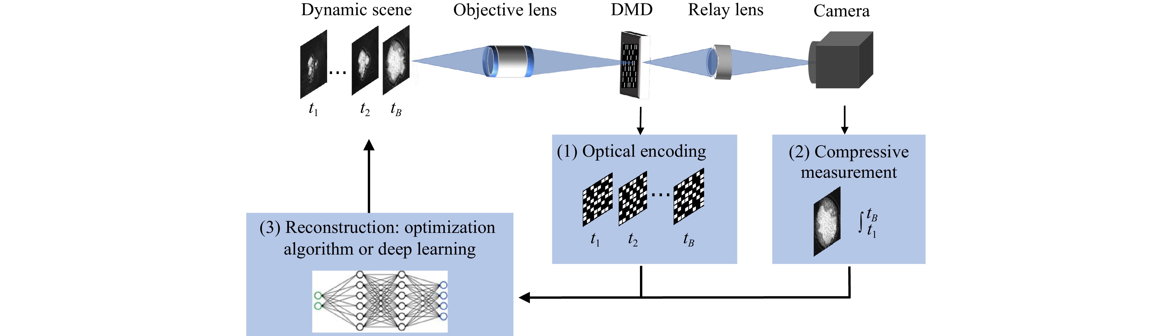
Fig. 1 Principle of snapshot compressive imaging, which consists of optical encoding, compressive measurement, and reconstruction.
We have formulated a forward imaging model for a snapshot temporal compressive imaging system. Let $ {\mathbf (x,y,t)} $ denote the spatiotemporal coordinate system of a dynamic scene $ {\bf{O}}(x,y,t) $. Temporally varying masks are defined as $ {\bf{C}}(x,y,t) $. The compressed measurement is modeled as the temporal integration of the product between the corresponding masks and the scene.
$$ I(x',y')=\int_{t=0}^{T}O(x,y,t) \bullet C(x,y,t) dt $$ (1) where $ {I(x',y')} $ is the continuous representation of the compressed measurement over exposure time $ T $.
In discretized form, considering $ B $ discrete time slots, $ B $ high-speed frames $ {\left \{ {{\bf{X}}}_{k} \right \} } _{k=1}^{B}\in {\mathbb R}^{n_x\times n_y} $ are modulated by the coding masks $ {\left \{ {{\bf{M}}}_{k} \right \} } _{k=1}^{B}\in {\mathbb R}^{n_x\times n_y} $. The discretized measurement is thus given by
$$ {\bf{Y}}= \sum\limits_{k=1}^{B} {{\bf{X}}}_k \odot {\bf{M}}_k+{\bf{G}} $$ (2) where $ \odot $ denotes the elementwise product. $ {{\bf{G}}} \in {\mathbb R}^{n_x\times n_y} $ represents measurement noise. Subsequently, the sensing process is vectorized. Define
$$ {\bf{x}}=\left[{\bf{x}}_1^ {\bf{T}},... , {\bf{x}}_B^ {\bf{T}} \right]^{{\bf{T}}} $$ (3) where $ {\bf{x}}_k = {{\bf{vec}}}(X_k) $ represents the vectorized formulation of the $ k $-th frame obtained by stacking the columns. Let
$$ \Phi=\left[{{\bf{D}}_1},{...},{{\bf{D}}_B}\right] $$ (4) where $ {\bf{D}}_k = Diag({{\bf{vec}}}({\bf{M}}_k)) $ represents the diagonal formulation of $ {\bf{M}}_k $ in the $ k $th frame, where each diagonal element corresponds to a value in its vectorized form. By reshaping the Eq. 2 using $ {\bf{x}} $ and $ \Phi $, we obtain the sensing process in its vectorized formulation,
$$ {\bf{y}}={\bf {\Phi x}} +{\bf {g}} $$ (5) where $ {\bf{y}}={\bf{vec}}({\bf{Y}}) $ and $ {\bf{g}}={\bf{vec}}({\bf{G}}) $. This formulation resembles the concept of compressed sensing but involves a unique structure in the sensing matrix $ \Phi $. We aim to recover $ {\bf{x}} $ given the measurement $ {\bf{y}} $ and the mask $ \Phi $. This is a typical ill-posed inverse problem that can be solved using optimization or deep-learning-based methods. In optimization-based methods, an additional term $ {\bf{R}}({\bf{x}}) $ is introduced as a regularization term that serves as prior information used to constrain the solution. Specifically, we can represent the reconstruction process as the following optimization task:
$$ \hat{{\bf{x}}}=\mathop{\arg\min}\limits_{{\bf{x}}} ||{\bf{y}}-{\Phi{{\bf{x}}}}||_2^2 + \tau {\bf{R}}({\bf{x}}) $$ (6) where $ \tau $ is a parameter that balances the data fidelity term $ ||{\bf{y}}-{\Phi{{\bf{x}}}}||_2^2 $ and regularization term $ {\bf{R}}({\bf{x}}) $. Various iterative algorithms have been proposed for solving this problem35, 36. Another solution to Eq. 5 learns the inverse modeling between the measurement $ {\bf{y}} $ and desired signal $ {\bf{x}} $ through a deep neural network32-34, 37. Formally, a deep learning-based algorithm minimizes the following problem through gradient descent (such as the Adam optimizer46):
$$ \hat{{\bf{w}}}=\mathop{\arg\min}\limits_{{\bf{w}}} ||{\bf{y}}-\Phi({{\bf{N}}({{\bf{w}}))}}||_2^2 $$ (7) where $ {\bf{w}} $ is the learnable weight optimized through training. After training, the reconstructed signal $ \hat{{\bf{x}}} $ can be obtained instantly by feeding the measurement $ {\bf{y}} $ into a pretrained neural network.
Principle
-
A schematic of our custom-built snapshot compression microscope is shown in Fig. 2. The setup is mainly composed of a femtosecond laser processing system, a high-resolution snapshot compressive microscope, and a wide field-of-view snapshot compressive microscope. The femtosecond laser (Fs laser, FLASH-100-IR, ULTRON Photonics) has a center wavelength of 1030 nm, a pulse duration of 150 fs, a maximum single pulse energy of 0.2 mJ, and a maximum repetition frequency (single pulse) of 10 MHz. The femtosecond laser was irradiated and focused on the sample plane using a beamsplitter and lens (L1, f = 200 mm). An infrared (IR) cut filter (F) was used after the objective lens to block the processing light. For the in-process monitoring of laser material processing, we employed a dual-path snapshot compressive microscopy system called DP-SCM. The DP-SCM system consists of two parallel optical paths, each optimized for a different range of lateral resolutions and FOV. Taking a high-resolution optical path as an example, a white light-emitting diode (LED) was used to illuminate the sample in a transmissive and wide-field manner. The samples were attached to a 2-axis motorized translation stage (GCD-202100M, Daheng Optics). The transmissive light from the sample was collected by an objective lens with a high numerical aperture (OL, 20×, NA = 0.42) and relayed to a digital micromirror (DMD, Vialux, DLP7000,768 × 1024 pixel count, 13.7 μm pixel pitch) through a long-focal-length lens (L2, f = 400 mm). The DMD imposes binary spatial modulation on the scene upon transmission. The modulated scene was then relayed onto the CMOS camera (STC-MBS202POE, Santech, 1624 × 1240 pixel count, 4.5 μm pixel pitch) through another lens (L3, f = 100 mm). The magnification rate between DMD and camera was 0.66, yielding 1:2 pixel mapping. The camera maintained a constant frame rate of 50 fps, whereas the DMD operated at frame rates ranging from 500 to 1000. This resulted in compression ratios (CR) spanning from 10 to 20. This corresponds to 10 to 20 times faster imaging speed (To clarify, a CR of 10 represents 10× compression). The total magnification of the high-resolution path is 26× times, which, in our case, guarantees high-resolution inspection of the sample with a limited FOV (approximately 215 μm). On the wide FOV path, we share the same OL for the collection of sample light but choose a small-focal-length lens (L4, f = 50 mm) to guarantee a smaller magnification (2.75×). Thus, optical resolution is sacrificed in exchange for a large FOV (approximately 2 mm). Notably, the DMD and CMOS in both paths are identical. Because both paths have their individual FOVs and resolutions, hereafter, we refer to FOV and HR as the FOV of the wide field-of-view path and the resolution of the high-resolution path, respectively, in our system.
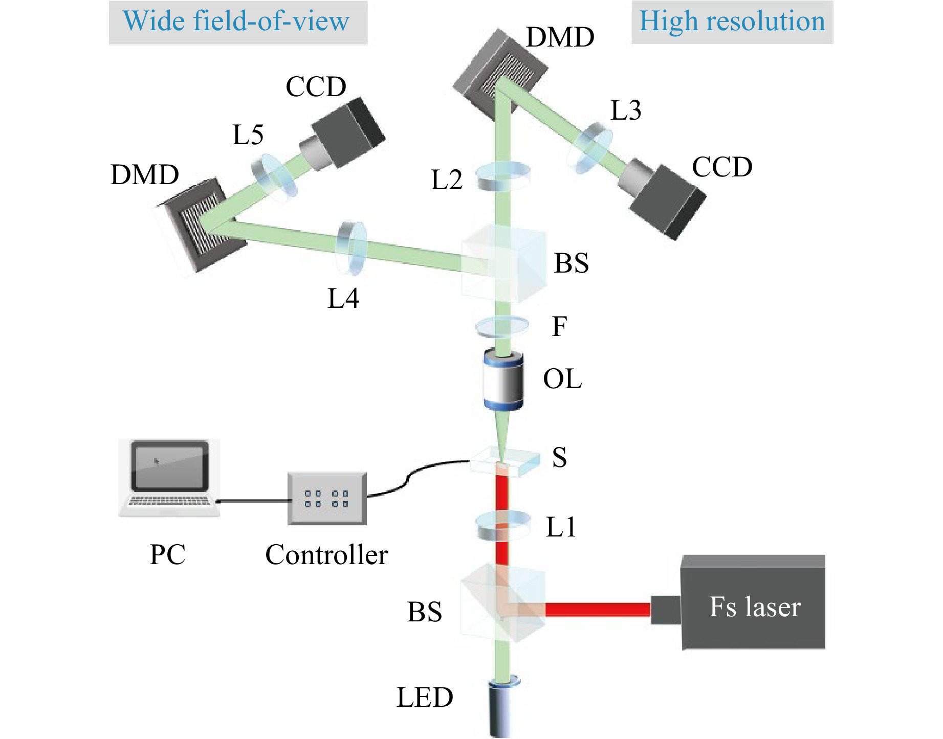
Fig. 2 Experimental setup of DP-SCM system. L1-L5, lens; OL, objective lens; BS, beamspliter; Fs laser, femtosecond laser; S, sample; F, IR cut filter; DMD, digital micromirror device; LED, light-emitting diode.
We began by validating our setup on a USAF resolution target (USAF 1951 high-resolution target, Edmund), as depicted in Fig. 3. In Fig. 3a, b, a standard USAF1951 test target was used to characterize the FOV and lateral resolution of our DP-SCM system. As shown in Fig. 3a, the full FOV of the system is 2 mm. However, when zooming into a smaller area, the details of the target resolution are completely lost. By employing another high-resolution path, the elements of the ninth group can be resolved. As shown in Fig. 3b, the lowest element corresponding to a line spacing of 645 lp/mm (775 nm in linewidth, which is quite close to the theoretical resolution with NA = 0.41) is observed in the high-resolution path compared with the zoomed-in image in the wide-field path in Fig. 3a. A detailed comparison of resolutions is presented in Supplementary Fig. S1.
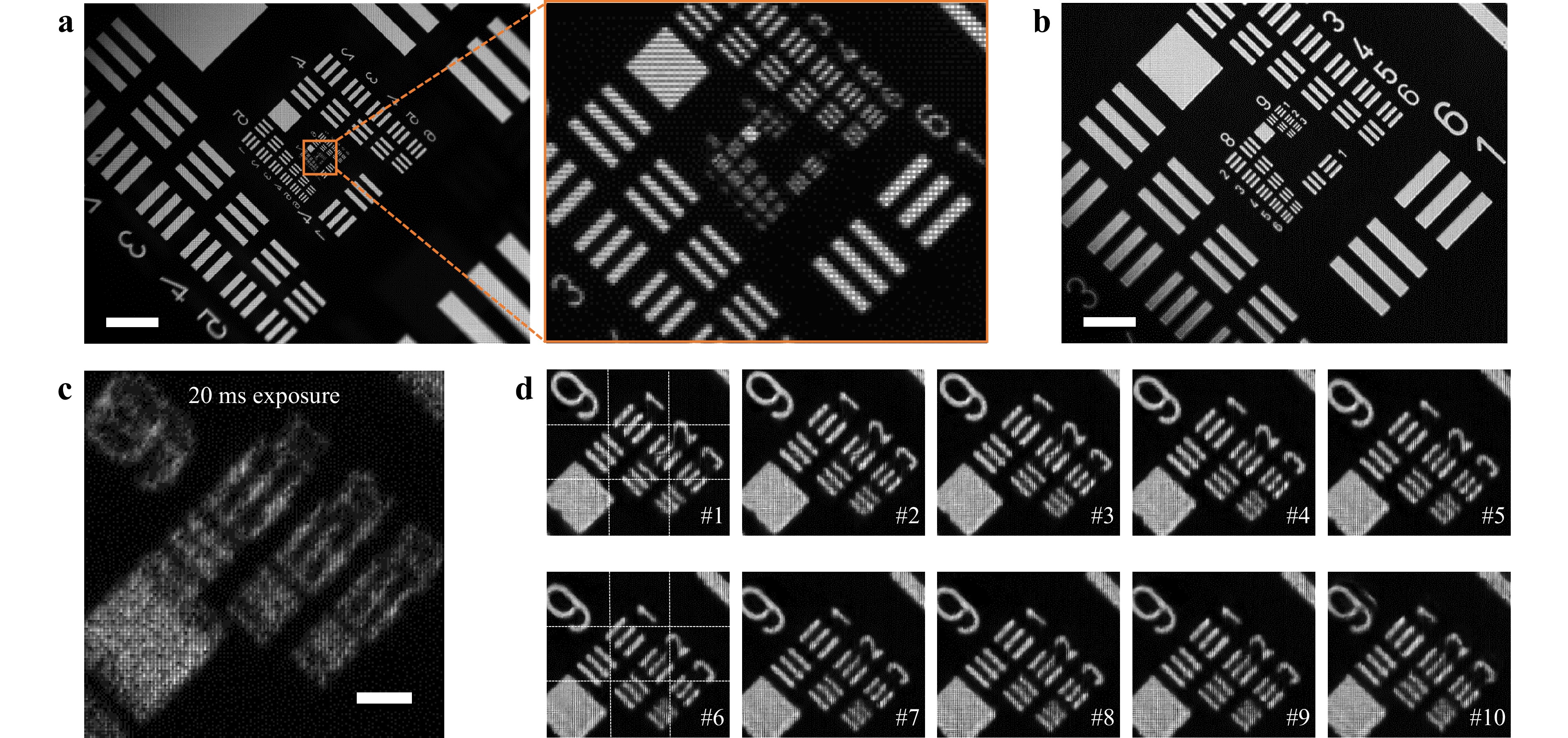
Fig. 3 Performance evaluation of DP-SCM system. a Wide field-of-view image (left) captured by FOV path, with zoom-in image (right). b High-resolution image captured by the HR path. c Compressed measurement under an exposure time of 20 ms, compressed ratio of 10. d Reconstructed frames from compressed measurement in c. Scale bars in a, b and c are 500 um, 50 um, and 5 um respectively.
In addition, we performed high-speed imaging using the DP-SCM system. Fig. 3c, d show a moving scene of the resolution target imaged using our system (see Visualization 1 for the complete video). Fig. 3c shows the compressed measurement captured with an exposure time of 20 ms. Within the exposure time, 10 random masks were sequentially displayed on the DMD, which provided a temporal resolution of 2 ms. By feeding the 10 masks (captured in advance) and compressed measurements into the EfficientSCI reconstruction algorithm34, we reconstructed high-speed scenes corresponding to a frame rate of 500 fps from a compressed measurement captured with a frame rate of 50 fps, as presented in Fig. 3d. It can be observed that the resolution target moves in the diagonal direction, and the elements of the ninth group can still be resolved with sharp edges. All reconstruction algorithms were executed on a computer with an NVIDIA A40 GPU.
Next, we compared the reconstruction performances of three algorithms (GAP-TV35, PnP-FastDVDnet36 and EfficientSCI37), as shown in Fig. 4. For better comparison, we selected the first recovered frame from the compressed measurement (see in Fig. 3c) as the baseline. GAP-TV is a regularization-based optimization algorithm used to solve the ill-posed problem in Eq. 6. PnP-FastDVDnet is a plug-and-play optimization algorithm that replaces the denoising step in a typical optimization-based algorithm with a deep denoiser (pretrained neural network), leading to better reconstruction and flexibility. Both regularization-based and plug-and-play optimization algorithms have been used in various snapshot compressive imaging systems. We compared both algorithms with the state-of-the-art EfficientSCI algorithm (one solution in Eq. 7), which trains the deep neural network in an end-to-end manner and makes efficient inferences. Building on the remarkable achievements of convolution and transformers in computer vision, we designed a reconstruction network that leverages the strengths of both techniques. A comparison of the reconstructed resolution target in Fig. 4b reveals the ability of the EfficientSCI network to recover distinct structural details. Regarding the reconstruction time, EfficientSCI achieved a significantly shorter interference time of approximately 2.5s for reconstructing a compressed measurement (with a compression ratio of 10 and image size of 800x800 pixels). This was significantly faster than that of GAP-TV (193s) and PnP-FastDVDnet (80s). In practical deployment, EfficientSCI achieves an interference time of approximately 0.9 s when the image size is reduced to 256 × 256 pixels, which meets the real-time imaging requirement. Hereafter, we use EfficientSCI network to reconstruct dynamic scenes during laser material processing.
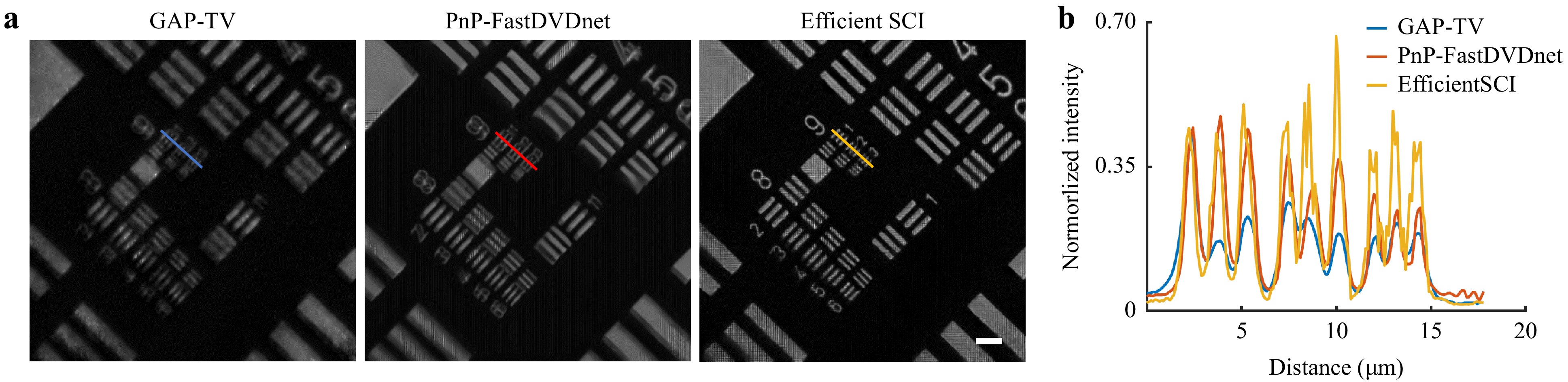
Fig. 4 Comparison of different reconstruction algorithms. a Results of GAP-TV, PnP-FastDVDnet, and EfficientSCI. b Line profile draw from a. Scale bar in a is 10 um.
-
In-situ real-time monitoring of laser material processing is shown in Fig. 5. We considered using a $ {\bf{Si-TiN}} $ bilayer film on an $ {\bf{Al_2O_3}} $ substrate as the processing sample. The sample was placed on top of a motorized stage. In the process of translating the stage, the focused femtosecond laser, under intense ultrafast laser irradiation, ablates the material, as shown in Fig. 5b. The repetition rate and laser power used in the experiment were 100 kHz and 0.5 mW respectively. We then used our system to capture the real-time ablation process using a camera operating at a frame rate of 50 fps. Fig. 5c, d show the measurements captured simultaneously by FOV and HR paths, respectively. Given the respective masks (setting the compression ratio to 10), high-speed laser material processing at 500 fps was observed. As illustrated in Fig. 5e, f, the two paths correspond to HR and FOV imaging modules. This indicated that even a slight movement in the FOV path became more pronounced in the HR path. Consequently, the movements illustrated in Fig. 5 may be difficult to discern; however, this becomes more apparent when magnified, as shown in Fig. 5f. The sample stage moved in the upper-right direction. Dynamic laser material processing is described in Visualization 2.
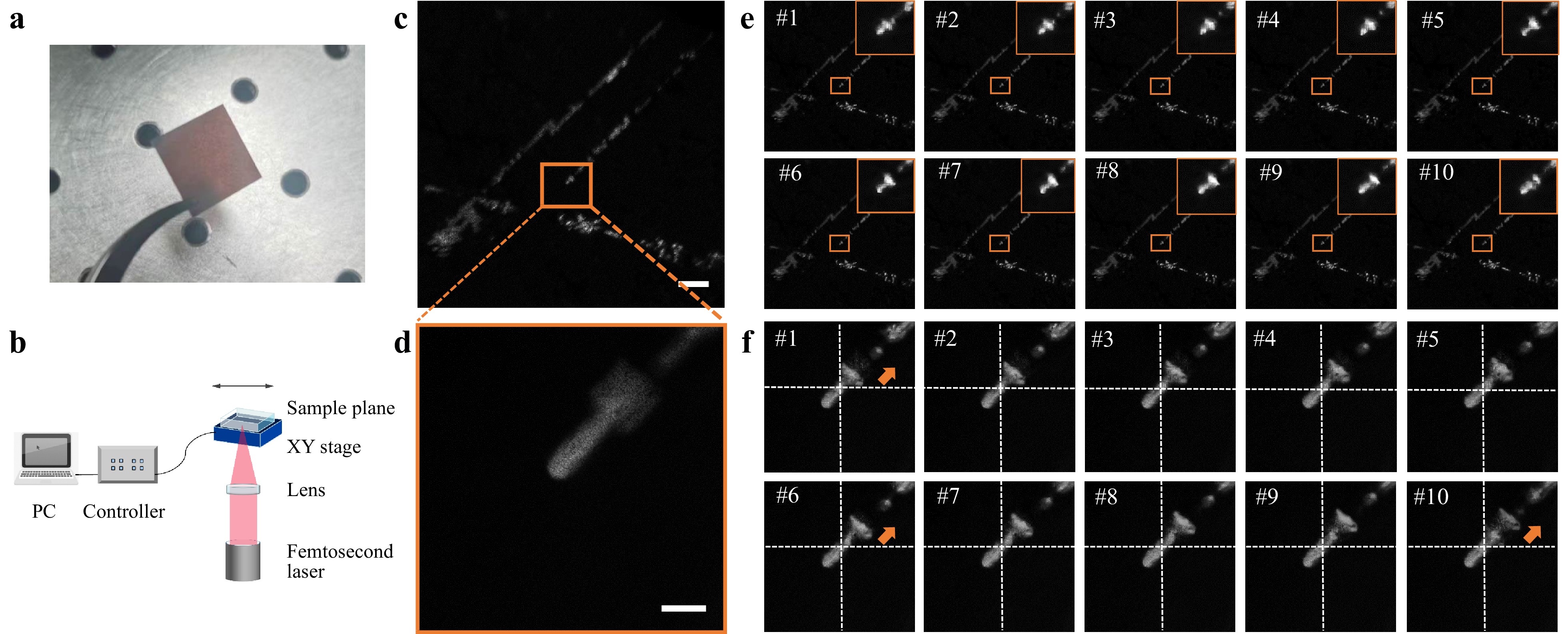
Fig. 5 In-situ and real-time monitoring of laser material processing when translating the sample stage. a Snapshot of processing material. b The translation stage is moving in one direction. c Compressed measurement captured by FOV path (exposure time = 20 ms, CR = 10). d Compressed measurement captured by HR path (exposure time = 20 ms, CR = 10). e Reconstruction by EfficientSCI from FOV measurement. f Reconstruction by EfficientSCI from HR measurement. Scale bars in c and d are 200 um and 20 um respectively.
Next, we examined real-time processing when femtosecond laser was scanned on the material (see in Fig. 6b). Using the same laser parameters and camera settings, we manually scanned the mirror while capturing the compressed scenes in the HR path. The measurements and reconstructions are shown in Fig. 6a, c. See Visualization 3 for a complete video. The femtosecond laser ablates the material at a 10 times higher speed than the measurement speed, which is captured at a normal camera frame rate. Scanning was performed in the upper-left direction. Apart from the simple scanning of the sample stage or steering mirror, our approach extends to monitoring the laser printing process, enabling intriguing applications such as customized pattern creation through laser printing. The experimental results are presented in Supplementary Fig. S2. We demonstrated the feasibility of our DP-SCM in the real-time monitoring of laser material manufacturing, regardless of laser scanning or stage scanning.
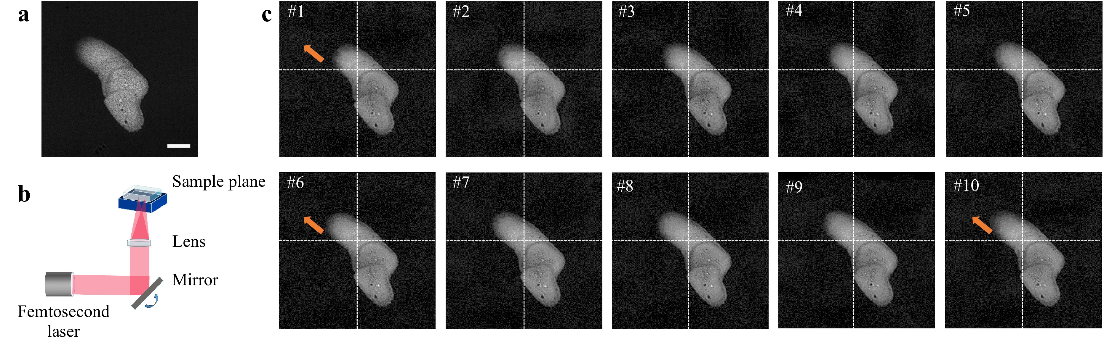
Fig. 6 In-situ and real-time monitoring of laser scanning process when scanning the focal point via rotating the mirror. a Compressed measurement captured under 20 ms in high-resolution path. b Schematic of laser scanning process. c Reconstructed frames with a compressed ratio of 10. Scale bar in a is 10 um.
-
To demonstrate the capability of DP-SCM in discovering more in-depth laser-material interactions, we investigated the generation of self-organized nanostructures. As reported in13, the laser-induced self-organization of periodic nanostructures on highly absorbing materials is commonly attributed to interference between the laser and surface plasmon polaritons (SPPs), which are initially excited by the inherent roughness of the surface. Interference between the laser beam and prominent surface-scattered waves leads to periodic variations in the optical intensity, consequently causing selective modulation of the surface. Consequently, periodic nanostructures acquire long-range alignment and orientation directly influenced by the phase and direction of surface-scattered waves, with their wavelength determining the structural periodicity. However, these periodic nanostructures often lack consistent regularity.
We first used our DP-SCM system to observe the self-organized periodic nanostructures. A femtosecond laser was focused on the material using a lens with a focal length of 100 mm. A self-organized periodic nanograting was observed in the HR path when we set the DMD to be statically blank (functioning as a mirror). As is displayed in Fig. 7b, the periodicity of this grating was measured to be 836 nm, which corresponds well with that reported in the literature13.
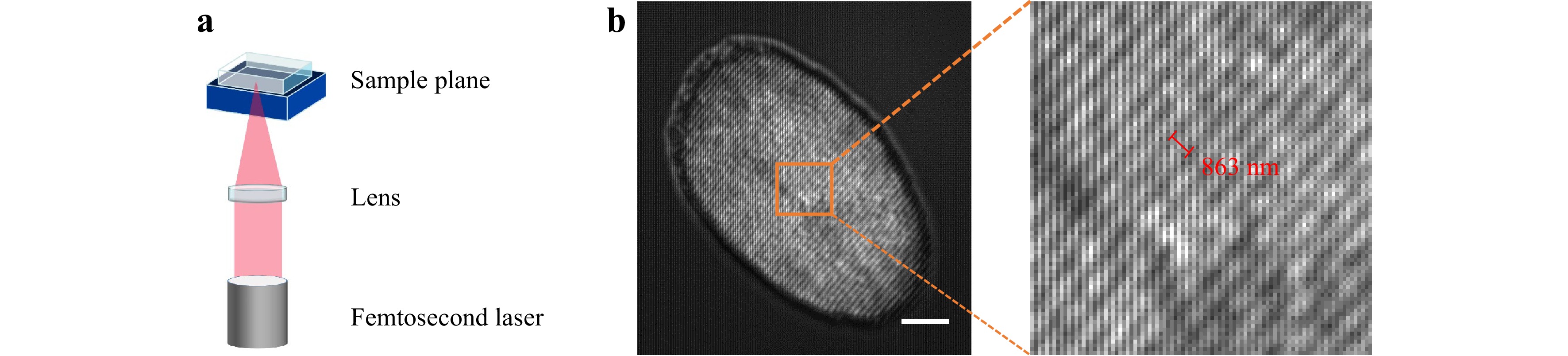
Fig. 7 Self-organized periodic nanostructures. a Setup for generating self-organized periodic nanostructures. b Captured nanograting structure in the high-resolution path (left), with zoom-in image (right). Scale bar in b is 10 um.
After demonstrating periodic nanostructures in a high-resolution path, we employed the DP-SCM system to observe the generation process. To compress the production process of self-organized periodic nanostructures into a single shot, we conducted numerous experiments to test the appropriate experimental conditions for observation because the repetition rate and laser power significantly affect the nanograting generation speed. The optimal repetition rate and laser power used in the experiment were 5 kHz and 5 mW respectively. Fig. 8 shows the experimental results when the compression ratio is 10, corresponding to a frame rate of 500 fps when the compression measurement is performed with an exposure time of 20 ms. We see from Fig. 8b, the nanograting grows slowly. In the reconstruction frames, the initial half of the frames nearly entirely captured this growth, whereas the subsequent timestamps showed no discernible changes in the growth of the nanograting. This is attributed to the insufficient speed of the imaging process. To visualize the entire growth process, we increased the compression ratio to 20, corresponding to a high-speed camera with a frame rate of 1000 fps, when the exposure time for one measurement was set to 20 ms. As shown in Fig. 9, the periodic structure can be visualized within 20 frames. These two reconstructed videos are placed in visualization 4 (CR = 10) and visualization 5 (CR = 20). The 1st reconstructed frame shows no periodic structure, whereas obvious growth can be seen in the following reconstructed frames, such as Frames 11 and 19. It should be emphasized that several laser pulses are involved in a single frame. To explore nanograting growth with fewer laser pulses, we reduced the femtosecond laser repetition rate to 1 kHz, aligning it at twice the speed of the reconstructed frame rate. In this manner, each reconstructed frame captured the interaction between the two laser pulses and the sample. The results are presented in Supplementary Fig. S3.
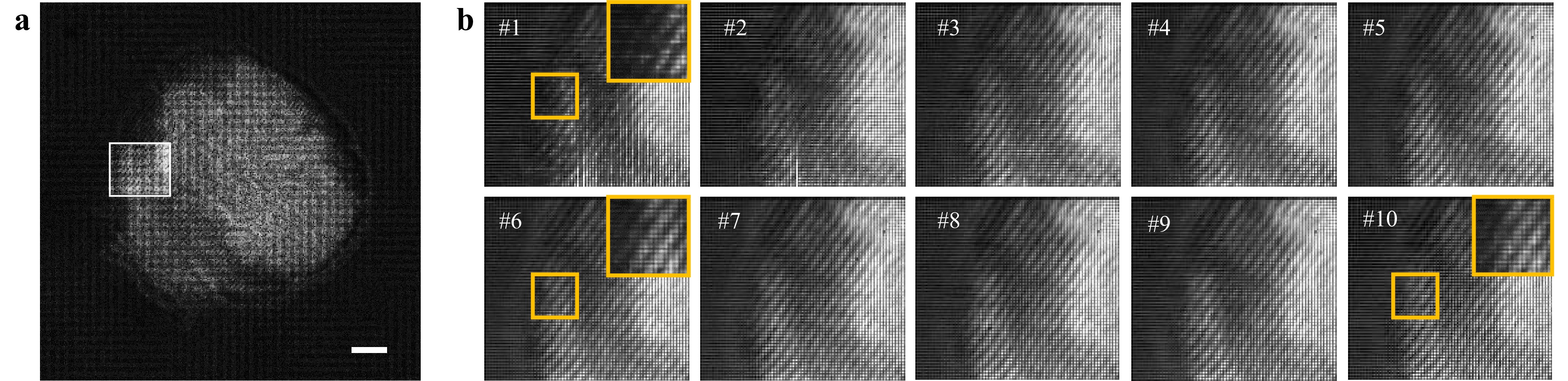
Fig. 8 In-situ and real-time monitoring of the growth of self-organized periodic nanostructures with a compressed ratio of 10. a Compressed measurement captured under 20 ms in a high-resolution path. b Reconstructed frames (corresponding to the white box area in a) with magnified images on the up-right corner (corresponding to the yellow box area). Scale bar in a is 10 um.
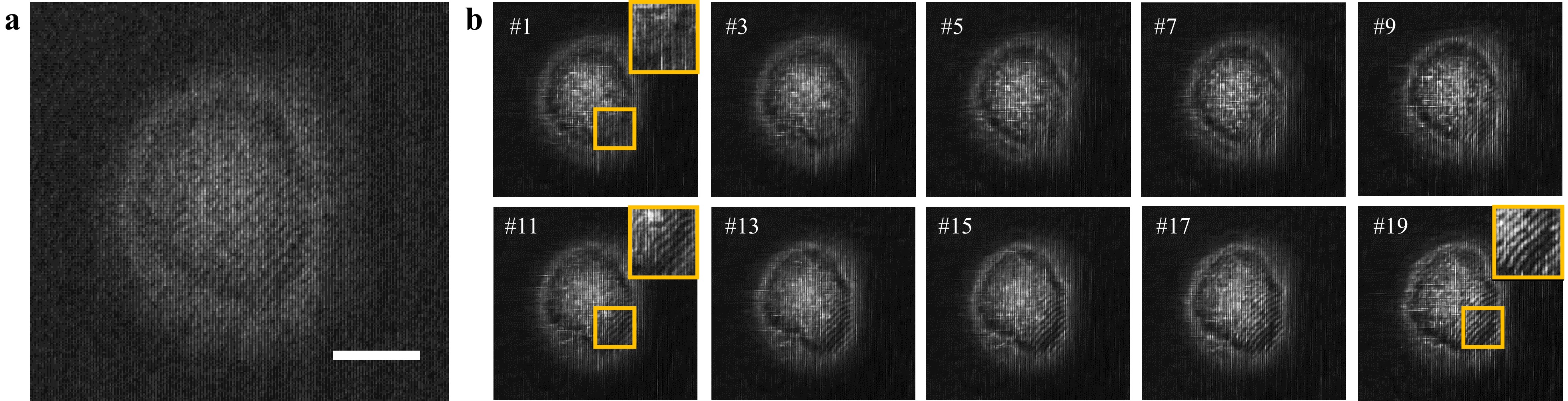
Fig. 9 In-situ and real-time monitoring of the growth of self-organized periodic nanostructures with a compressed ratio of 20. a Compressed measurement captured under 20 ms in a high-resolution path. b Reconstructed frames are presented, showcasing one frame for every two images, along with magnified images in the upper-right corner, corresponding to the yellow box area. Scale bar in a is 10 um.
It should be noted that the signal-to-noise ratio of the reconstructed frames with a compression ratio of 20 was much lower than that with a compression ratio of 10. This is because a higher compression ratio always results in a lower dynamic range because a shorter temporal exposure (temporal resolution) is present. Further details on this aspect can be found in Supplementary Fig. S4. This problem can be mitigated by devising novel algorithms that operate under low-light conditions or by using low-light images to train the network.
Experimental setup
Inspection of laser material processing
Inspection of self-organized periodic nanostructure
-
In summary, the in-process real-time monitoring of laser material manufacturing was demonstrated using our custom-built DP-SCM system. To evaluate the performance of the DP-SCM system, the FOV and lateral resolution were measured as 2 mm and 775 nm respectively. A frame rate of 500 fps was validated using a conventional camera operating at a frame rate of 50 fps. Moreover, we compared three reconstruction algorithms and selected the state-of-the-art EfficientSCI algorithm. To validate the feasibility of the system for in-process laser material processing, experiments were conducted in which the laser or translation stage was scanned across the sample plane. The results showcase the superiority of DP-SCM in imaging speed in terms of laser material processing. Furthermore, we performed in-situ and real-time monitoring of the growth of self-organized periodic nanostructures. With an imaging speed of 500 fps (exposure time of single measurement = 20 ms, CR = 10), we can observe the partial growth of nanograting. When increasing the CR to 20, corresponding to an imaging speed of 1000 fps, the entire growth process of nanograting could be visually observed. Therefore, we validated that DP-SCM is capable of visualizing ultrafast laser processing and uncovering novel phenomena of laser-material interactions. The imaging setup is in a transmissive module, which can also be adapted to the reflection setup according to the transparency of the manufactured sample.
The proposed method features wide-field and high-resolution high-speed imaging. Wide-field and high-resolution imaging help visualize the entire process with finer details, which is applicable to all imaging systems that require in-situ monitoring. For scenarios that require a higher imaging speed, conventional cameras (working at a frame rate below 500 fps) fail to provide sufficient temporally resolved information. Our strategy offers a fast imaging method to visualize the process at a relatively low cost and low bandwidth.
Snapshot compressive imaging not only compresses the temporal signals but also 3D47 and spectral information48, which can be used to inspect the 3D structure49 and structural color50 in in-situ real-time laser processing. Finally, this system can be readily accommodated in other laser processing setups to enable high-speed imaging. We expect that this snapshot compressive imaging system will find applications in laser processing and other manufacturing inspections.
-
This work was supported by the National Natural Science Foundation of China (62271414), Science Fund for Distinguished Young Scholars of Zhejiang Province (LR23F010001), Research Center for Industries of the Future (RCIF) at Westlake University. and Key Project of the Westlake Institute for Optoelectronics (Grant No. 2023GD007).

 DownLoad: