


-
Optical glass has been extensively used in various applications such as lenses for imaging and illumination, laser systems, sensors, aerospace, and microelectronics1–3 owing to its excellent physical and chemical properties including a high heat-resistance, corrosion-resistance, wear-resistance, strength, hardness, and transparency, which meets the application requirements4,5. To meet the superior functional requirements in the applications, optical glass should have an ultra-smooth surface finish at the nanometer or sub-nanometer scale, surface form accuracy at the sub-micrometer scale, and low sub-surface damage, which is commonly achieved by the polishing process after grinding or shaping the glass components6.
Recently, ultra-precision polishing processes, such as magnetorheological finishing7–9, fluid jet finishing10–12, bonnet polishing13,14, ion beam finishing15,16, and chemical-mechanical polishing17 have been rapidly developed to precisely polish flat, spherical, aspherical, or freeform optical glass, meeting the aforementioned requirements of the surface quality. Wang et al.18 proposed a universal dwell time optimization model and applied it to an ion beam figuring system to improve the surface form accuracy of a synchrotron X-ray mirror; a root-mean-square (RMS) figure error of 0.19 nm was achieved in the clear aperture from a RMS of 6.32 nm within 4 min. Guo et al.19 proposed a Halbach array-excited MRF to improve the magnetic strength and polishing efficiency, where simulations and experiments were performed on an optical glass workpiece. The results demonstrated that the surface roughness rapidly decreased from 500 nm to 0.6 nm within 90 min of polishing, achieving a polishing efficiency that was 4 times higher. Amir et al.20 applied a magnetic-nanoparticle-based MR fluid, eliminating the use of carbonyl iron particles (CIP), to polish flat BK7 glass and achieved a final roughness of Ra 22 nm. Baghel et al.21 further improved ball-end magnetorheological finishing by adding a vibration motion to the workpiece to enhance optical glass corrective polishing, achieving a surface roughness of 3 nm and a figure error of 148 nm after polishing. Liang et al.22 proposed an ultrasonic-assisted vibration polishing method for polishing large optical lenses; a theoretical analysis and experiments were performed to determine the optimal conditions, which demonstrated that the surface roughness (Ra) reduced from 12 µm to 8 nm on a 300-mm diameter lens. Xu et al.23 and Tan et al.24 reported an ultra-smooth optical glass surface with Ra values of 0.093 nm and 0.04 nm, respectively, using chemical mechanical polishing on a flat workpiece. Recently, Peng et al.25 proposed a series of layer-by-layer laser ablation processes to remove the defects and sub-surface damages in fused silica optics, which can achieve a nanoscale ablation depth and sub-nanometer surface roughness with a 65% improved laser-induced damage threshold compared to conventional processes. However, the aforementioned ultra-precision polishing technologies usually process the optical components piece-by-piece, requiring a specific processing environment or a strict limitation in the shape of the workpiece, leading to a low polishing efficiency and high production cost. Therefore, their widespread use for industrial purposes has been limited despite the increasing demand for general optical glass components with a micrometer-scale surface form accuracy and nanometer-scale surface finish requirements.
Current industrial mass finishing technologies, such as vibratory finishing and26,27 rotary barrel finishing28,29, which target the surface finishing of large batches and a high cost-effectiveness, are usually adopted for the polishing of metal or ceramic components but are not suitable for optical glass components. Moreover, the probability of maintaining the surface accuracy and quality of the surface finish using these types of mass-finishing processes is relatively low and cannot meet the functional requirements of optical components30. Research regarding mass-finishing technologies has been conducted to model the abrasive media flow, kinematics, and material removal mechanism26,31–34, while rarely focusing on improving and integrating the mass-finishing processes for an improved surface form, dimension maintainability, and surface quality. Wang et al.27 studied the correlation of normal contact forces with respect to the hardness and change in surface roughness in vibratory finishing, concluding that the hardness and change in roughness were dependent on the lubrication condition and impact contact condition induced by the media roughness despite the varying impact force parameters. Barletta et al.35 combined the drag-finishing process with a fluidized bed to eliminate the formation of humid residuals during the conventional drag-finishing process; experiments were performed on brass rings with varying rotational speeds and exposure times to examine the performance. The surface roughness of the brass ring reduced from 3 µm to 0.17 µm after 3 h of polishing; however, the radius of the ring was reduced by a minimum of 25 µm. Umehara et al.36 developed an apparatus for finishing a large batch of silicon nitride ceramic balls using the magnetic float polishing process; an average surface roughness (Ra) and sphericity of 8 nm and 0.25 µm were obtained after polishing for 30 h, which were initially 900 nm and 23 µm, respectively. Li et al.37 proposed a novel floating clamp approach using rotary barrel finishing for a steel-bearing ring surface to improve the uniformity, and effectively reduced the variation coefficient of the surface roughness from 12% to 7%. Conventional mass-finishing methods have a relatively low surface finish, form accuracy, and limited working materials, such as steel and aluminum, while none have worked on batch optical glass polishing. Few studies have focused on the precision maintainability in mass-finishing technology. Therefore, it is necessary to develop an efficient and accurate mass-finishing process for optical glass polishing to meet the increasing market demand for spherical, aspherical, and freeform optical components.
To address the aforementioned research gap, this study proposes a magnetic-field-assisted batch polishing (MABP) method that can achieve the batch polishing of flat, curved, and structured surfaces of optical components.
-
In the experiment shown in Table 1, three types of polishing slurries: 0.125 µm diamond abrasive, 0.55 µm cerium oxide, and 0.5 µm diamond abrasive, namely slurries A, B, and C, respectively, were examined and recorded for 20 min. Fig. 1 presents the polishing performance of the different types of polishing slurries with respect to the polishing time, where Slurry A demonstrated the most significant and rapid improvement throughout the polishing process, achieving a final Sa value below 1 nm after 20 min of polishing. Slurries B and C demonstrated a slightly different trend compared to Slurry A, where a constant reduction in the surface roughness was observed in the first 10 min, which gradually reached the lowest roughness at approximately 12 nm. The surface textures before and after 20 min of polishing with each type of polishing slurry are shown in Fig. 2. Compared to the surface before polishing (Fig. 2a), the scratch marks were thoroughly removed with Slurry A (Fig. 2b), and an arithmetic mean height (Sa) of 0.5 nm and root-mean-square height (Sq) of 0.7 nm were obtained, demonstrating smooth and clean surfaces in the scanning electron microscope (SEM) image. A similar textured pattern was also obtained using Slurry C, as shown in Fig. 2d, where most of the scratches were removed but the resulting surface was relatively rough with small pits, which obtained average Sa and Sq values of 11.4 and 16.7 nm, respectively. When Slurry B was used, the scratches were partially removed (Fig. 2c); however, deep scratch marks from different directions and pits remained, leading to a relatively low surface quality and average roughness Sa and Sq values of 11.7 nm and 17.5 nm, respectively.
Conditions Group 1
Polishing SlurryGroup 2
Rotational speedGroup 3
ConfirmationTarget surface Flat Flat Convex, Concave, Structured Polishing slurry A, B, C A* A* Rotational Speed (rpm) 1500 500, 1000, 1500 500* Slurry concentration (wt.%) 25 25 25 Polishing time (min) 5, 10, 15, 20 10* 10* *Determined based on previous experimental results. Table 1. Experimental parameters and conditions
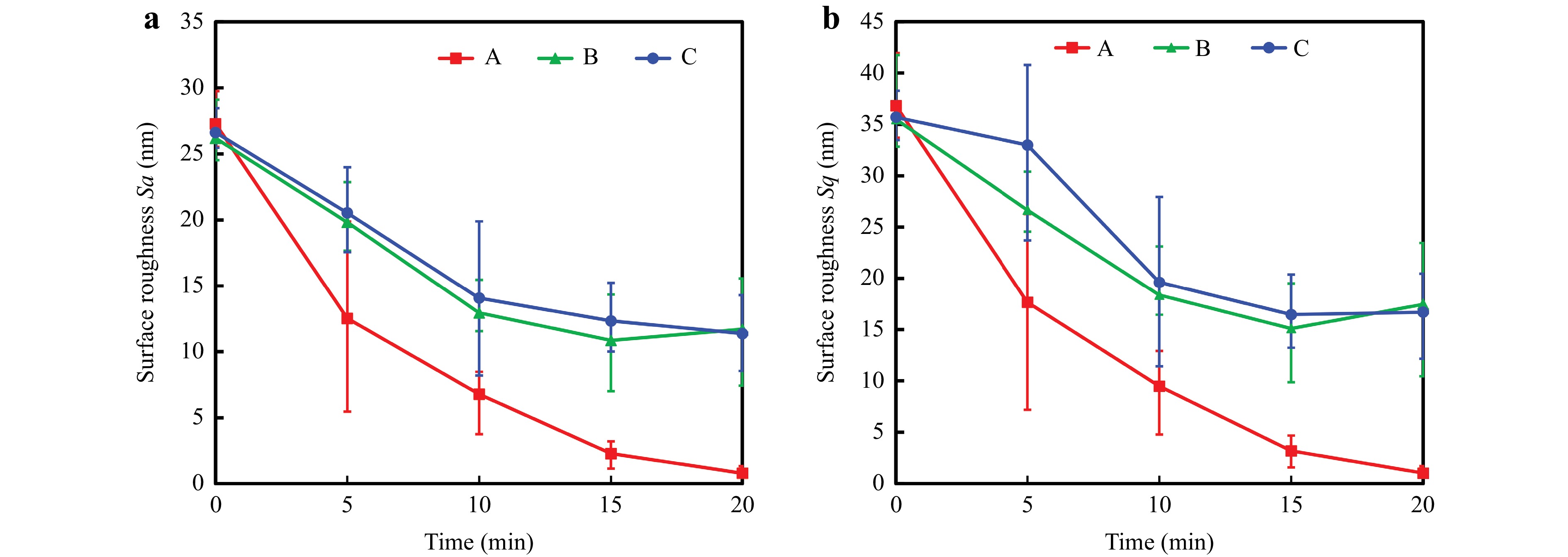
Fig. 1 Change in surface roughness over time by using Slurries A (Diamond 0.125 µm), B (Cerium oxide 0.55 µm), and C (Diamond 0.5 µm) with respect to the a arithmetic mean height (Sa) and b root mean square height (Sq).
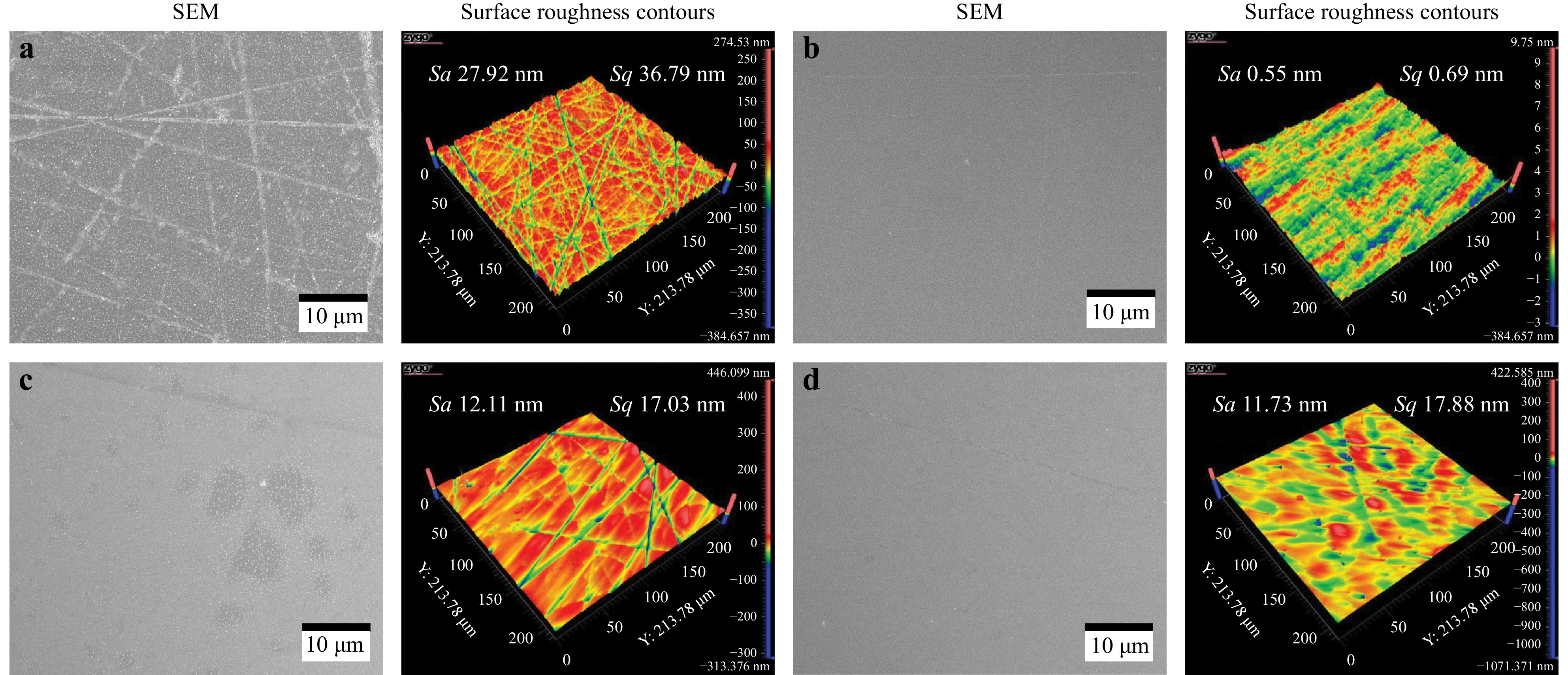
Fig. 2 Surface integrity of the optical glass surface before and after polishing with the different slurries: a before polishing, b Slurry A (Diamond 0.125 µm), c Slurry B (Cerium oxide 0.55 µm), and d Slurry C (Diamond 0.5 µm).
Considering the aforementioned results, Slurries A and C composed of the diamond abrasives demonstrated a higher polishing efficiency and significant improvement in the surface texture. Based on the roughness contours and SEM graphs, scratch marks polished by diamond Slurries A and C were removed more thoroughly than those polished by slurry B composed of cerium oxide. However, the larger particle size of Slurry C may have led to a coarser finished surface. The results indicate that Slurry A, which was composed of diamond abrasives with an average particle size of 125 nm and additives, best suits the function of optical glass polishing owing to the high material removal caused by the fine diamond abrasive particles.
-
Based on the aforementioned results, Slurry A composed of the fine diamond abrasive particles was selected for polishing in the second group of experiments to examine the effect of the rotational speed of the magnetic brushes on the optical glass. The slurry was mixed with an adequate proportion of CIPs to form magnetic abrasives. Considering the polishing efficiency, a 10-min polishing time was adopted to allow for a better comparison; the detailed experimental setup is shown in Table 1. Three different rotational speeds (500, 1000, and 1500 rpm) were examined with a constant polishing time, and the slurry type, magnetic abrasive composition, surface roughness, and SEM images were measured and compared before and after the polishing process. Fig. 3 presents the change in the roughness at different rotational speeds. Note, a lower rotational speed of 500 rpm resulted in the greatest reduction of the surface roughness after only 10 min of polishing, achieving an arithmetic mean height (Sa) and root-mean-square height (Sq) below 1 nm, which were initially 26 and 36 nm, respectively. Considering the other rotational speeds, 1000 and 1500 rpm demonstrated similar final values ranging from 4–8 nm, conforming to the results from the previous experiment (Group 1).
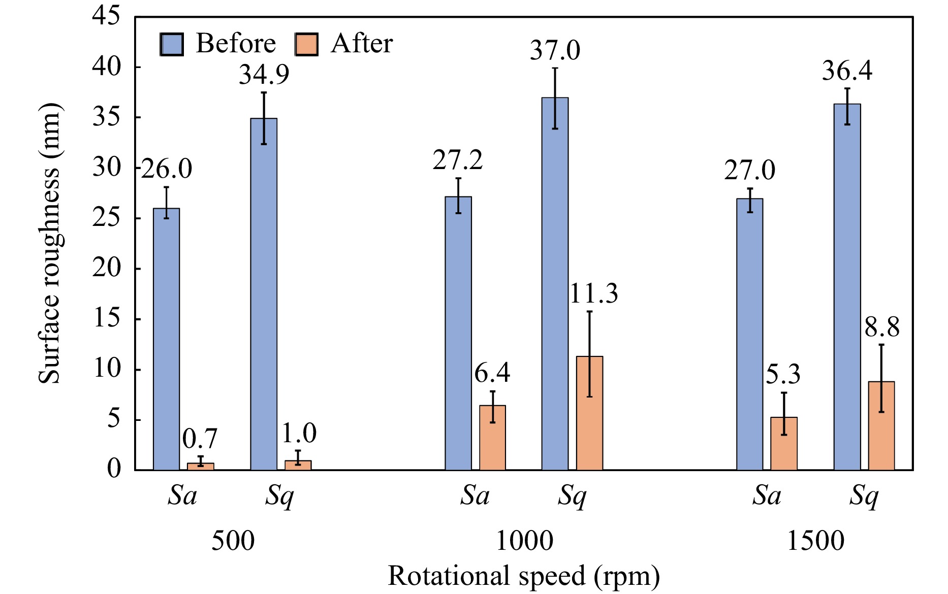
Fig. 3 Surface roughness before and after polishing with different rotational speeds.
Fig. 4 presents the SEM images and 3D contours captured after 10 min of polishing at 500 and 1500 rpm, respectively, to examine the surface texture. The optical glass polished with Slurry A for 10 min at 500 rpm exhibited a smooth and clean surface. However, at 1500 rpm, scratches and pits were observed, which were all pointed in the same direction, similar to the polishing direction. This phenomenon may be induced by the high rotational speed at which the impinging force drove the diamond abrasive particles to be embedded into the surface and roll over the workpiece during the polishing process, creating scratches and pits.
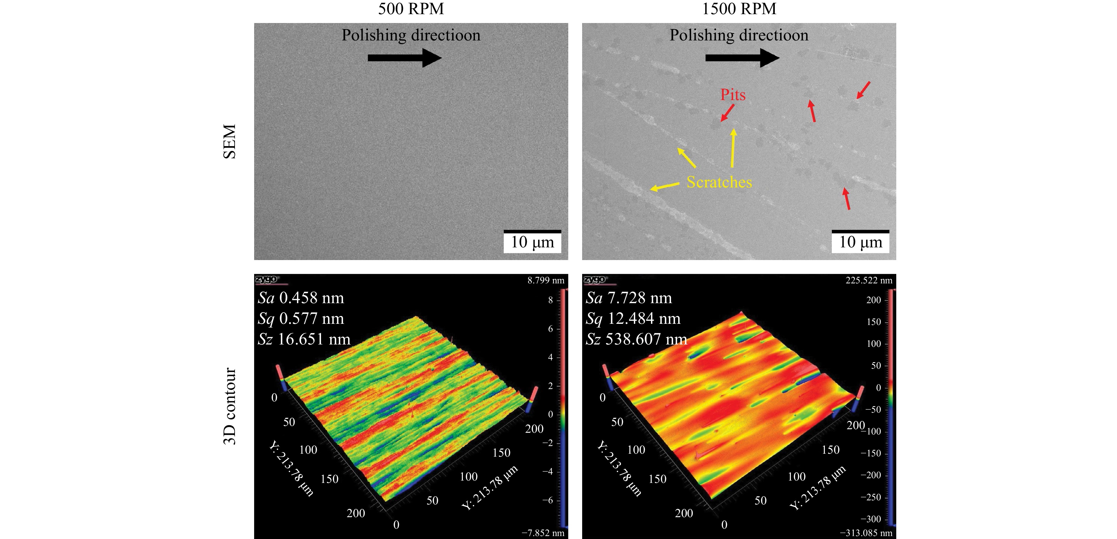
Fig. 4 Surface textures using different rotational speeds and polished for 10 min.
-
The depth of the material removed was also measured by polishing a flat optical glass surface using the following optimal parameters: a rotational speed of 500 rpm, an impingement angle of 15°, and Slurry A for 10 min, with half of the surface (a semicircle) covered, as shown in Fig. 5. The depth of the material removed in the uncovered area was 1.67 µm after polishing for 10 min using the optimized parameters; the peaks were smoothened after polishing, as compared with the covered area. The results indicate a high polishing efficiency of the MABP method for optical glass components, where the material removal rate reached approximately 167 nm/min. However, the material removal was not uniform across the workpiece surface positions. More material was removed on the right side of the workpiece than on the left side, possibly owing to the inclined impingement angle, leading to a varying magnetic field strength over the component surface. The polished area near the chamber wall experienced a higher magnetic field strength (~0.5T), whereas a lower strength (~0.4T) was observed mid-way through the tunnel, thereby affecting the shearing force of the abrasives on the surface of the workpiece. This difference resulted in a slightly non-uniform material removal along the polishing direction, regardless of the component shape. The non-uniformity can be mitigated by better controlling the impingement angle to adapt more effectively to the surface shape, thereby improving the uniformity of surface polishing.
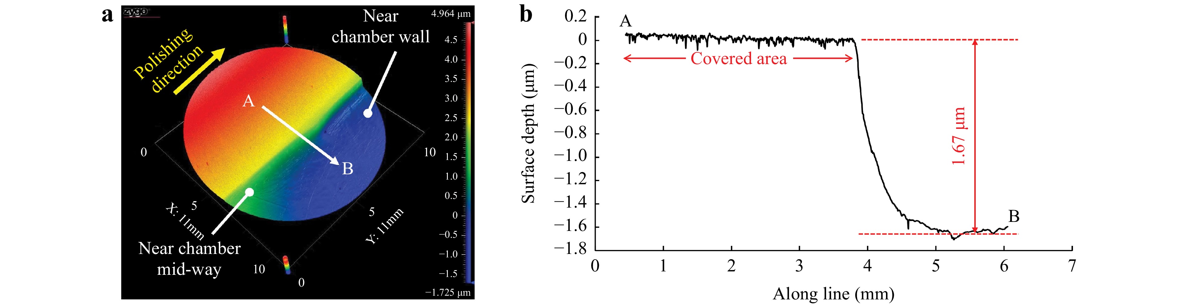
Fig. 5 Depth of material removal with optimal polishing parameters: a partial polished surface; b measured profile of the material removal.
-
A confirmation experiment was performed on convex, concave, and structured optical glass components using the optimized parameters listed in Table 1. Polishing Slurry A (125 nm diamond particle) was used owing to its superior polishing performance, and polishing was conducted for 10 min at a rotational speed of 500 rpm on three workpieces of each geometry simultaneously. The curved surfaces were all lapped with #2500 silicon carbide sandpaper before polishing, resulting in a surface roughness (Sa) ranging from 25−45 nm. The structured surfaces were fabricated via hot embossing, resulting in initial surface roughness values of Sa = 16 nm and Sq = 22 nm. The impinging angle was selected based on the method listed in the following section (determination of impingement angle), which demonstrates that the calculated minimum angles for the convex and concave R25.75 mm components were 6.1° and 23.8°, respectively, whereas that for the structured component was 8.7°. The impingement angle in the MABP experimental setup was controlled by an increment of 15°; thus, an angle of 15° was selected for polishing the convex and structured surfaces, and 30° was selected for polishing the concave surfaces.
Fig. 6 and 7 present the experimental results and measured topography of the polished curved samples, respectively. Fig. 6 demonstrates that regardless of the initial surface roughness, Sa values of approximately 1 nm or less were achieved after 10 min of polishing in all the polished samples, implying an effective and uniform surface finishing using MABP on multiple samples. To further investigate the limitations of the MABP method on the surface quality of optical glass polishing, the surface roughness after 20 min of polishing was also presented, which reached an Sa value of approximately 0.4 nm. The change in the surface quality was not significant after 20 min of polishing. Snapshots of the curved optical glass before and after the polishing are shown in Fig. 7a, where scratches on the glass surface were thoroughly removed after polishing, and a clear crystal lens can be observed in Fig. 7b. The surface roughness indicated by Sa was significantly reduced from 28 to 0.7 nm after 10 min of polishing, which was similar to the experimental results (Fig. 7c, d) of Group 2, and polishing traces pointing towards the polishing direction are demonstrated in Fig. 7d, f, respectively. The micro-surface roughness measured by atomic force microscopy (AFM) for a 20 × 20 µm area decreased from 20 to 0.7 nm, as shown in Fig. 7e, f.
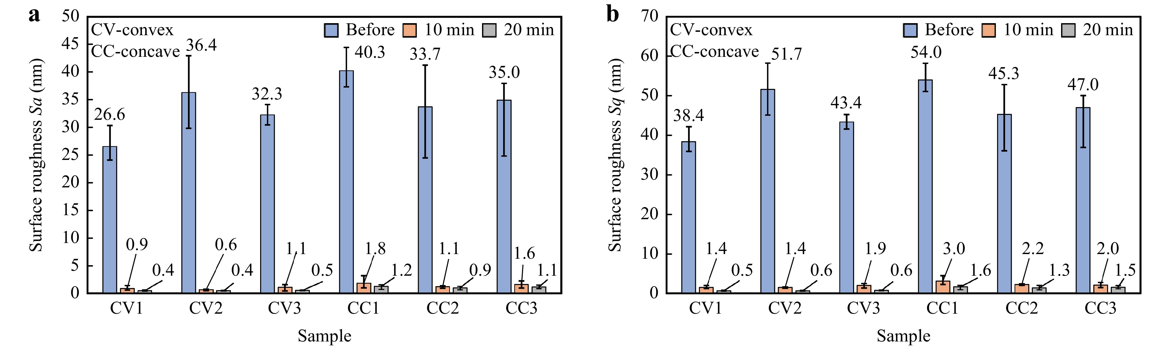
Fig. 6 Difference in the surface roughness before and after polishing using the optimized parameters: a arithmetic mean height (Sa); b root mean square height (Sq).
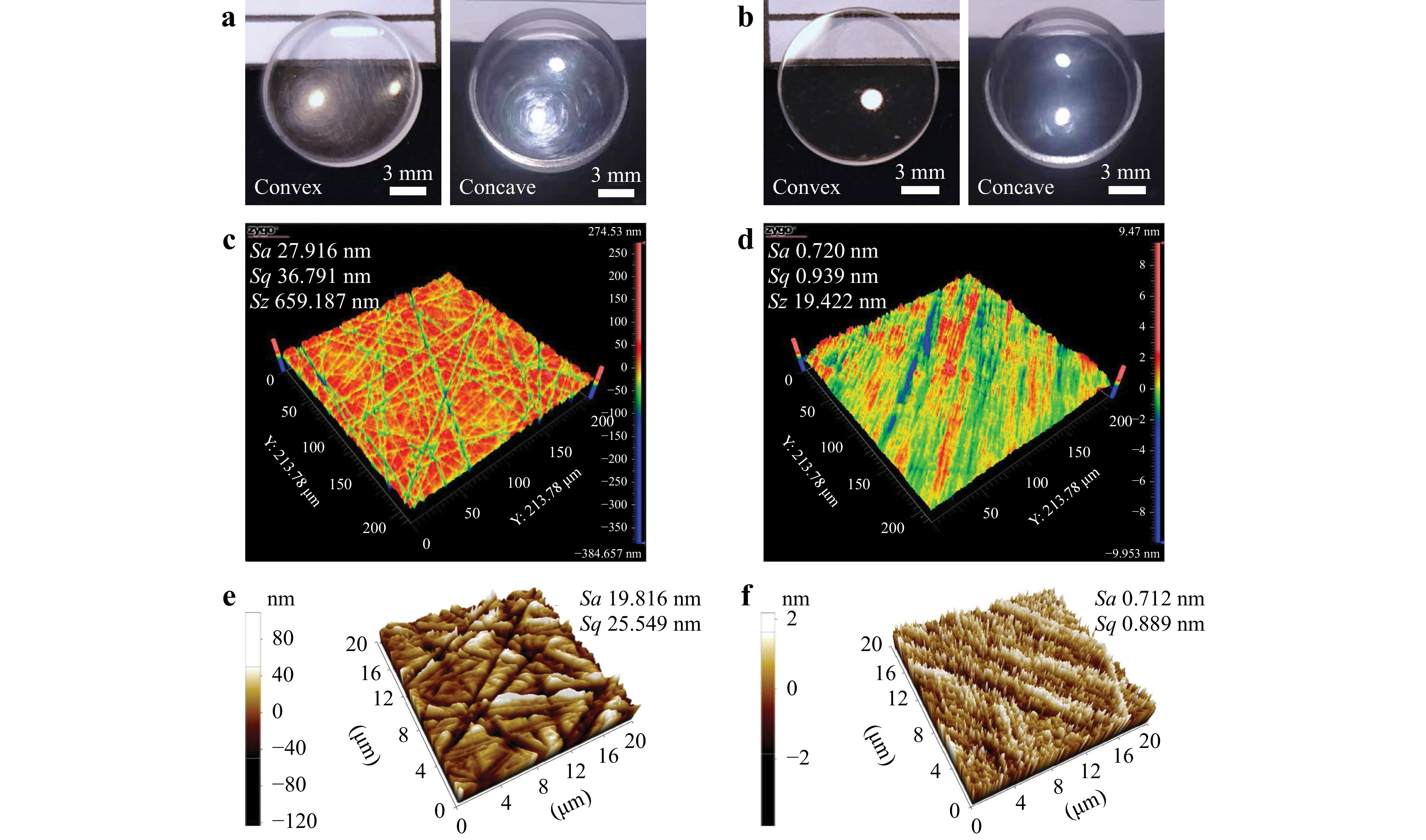
Fig. 7 Surface topography of the convex and concave lens before a,c,e and after b,d,f polishing: a,b snapshot, c,d surface roughness contours, and e,f AFM.
The performance of the MABP on the structured optical glass is shown in Fig. 8, demonstrating that the machining marks along the structured area after hot embossing diminished, as shown in Fig. 8a, which improved the light transmission. Based on the experimental results shown in Fig. 8b, c, the surface roughness significantly improved from initial Sa and Sq values of 17 and 21 nm, to 0.9 and 1.8 nm, respectively. A smoother surface was obtained after polishing for 10 min; furthermore, the deviation of the surface roughness over the structured surface was significantly reduced, implying an effective polishing of the structured optical glass to the nanometer-scale using the MABP, as indicated by the surface roughness.
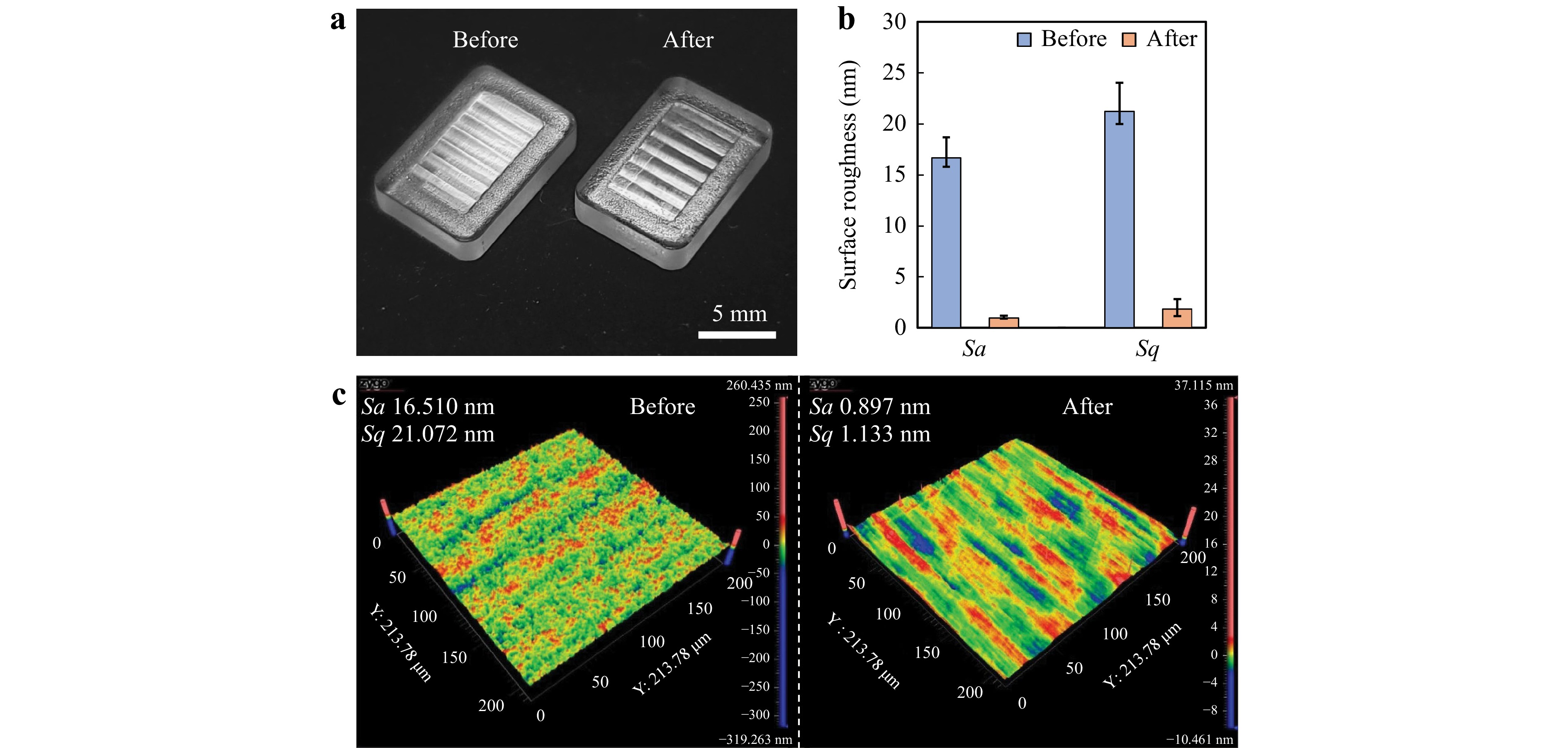
Fig. 8 Polishing performance on the structured surface: a snapshot, b comparison of the surface roughness with respect to Sa and Sq, and c surface roughness contours before and after polishing.
A focused ion beam (FIB; FEI Scios DualBeam microscope) was used to observe the subsurface damages of the polished optical glass, as shown in Fig. 9. No apparent cracks were observed after the polishing process, implying the promising performance of MABP, and demonstrating that it poses no additional subsurface damage in glass polishing.
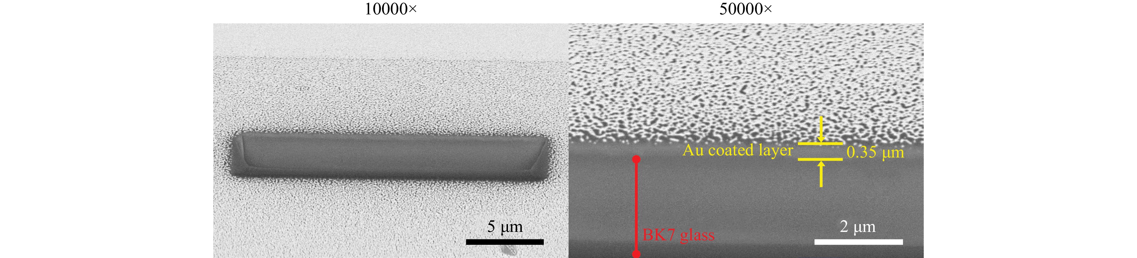
Fig. 9 Subsurface captured after MABP.
-
Fig. 10 and 11 present the surface form of the convex and concave glass before and after polishing measured along the polishing direction (x-) and normal to polishing direction (y-). The surface-form profiles of the convex and concave components in both directions were highly coincident before and after polishing, and the deviations of the profiles were extracted for easier comparison. Slight form errors of 0.75 and 0.89 µm were observed on the x-direction of the polished convex and concave lens, respectively, as shown in Fig. 10a and 11a, whereas small form deviations of 0.33 (Fig. 10b) and 0.41 µm (Fig. 11b) were observed in the y-direction.
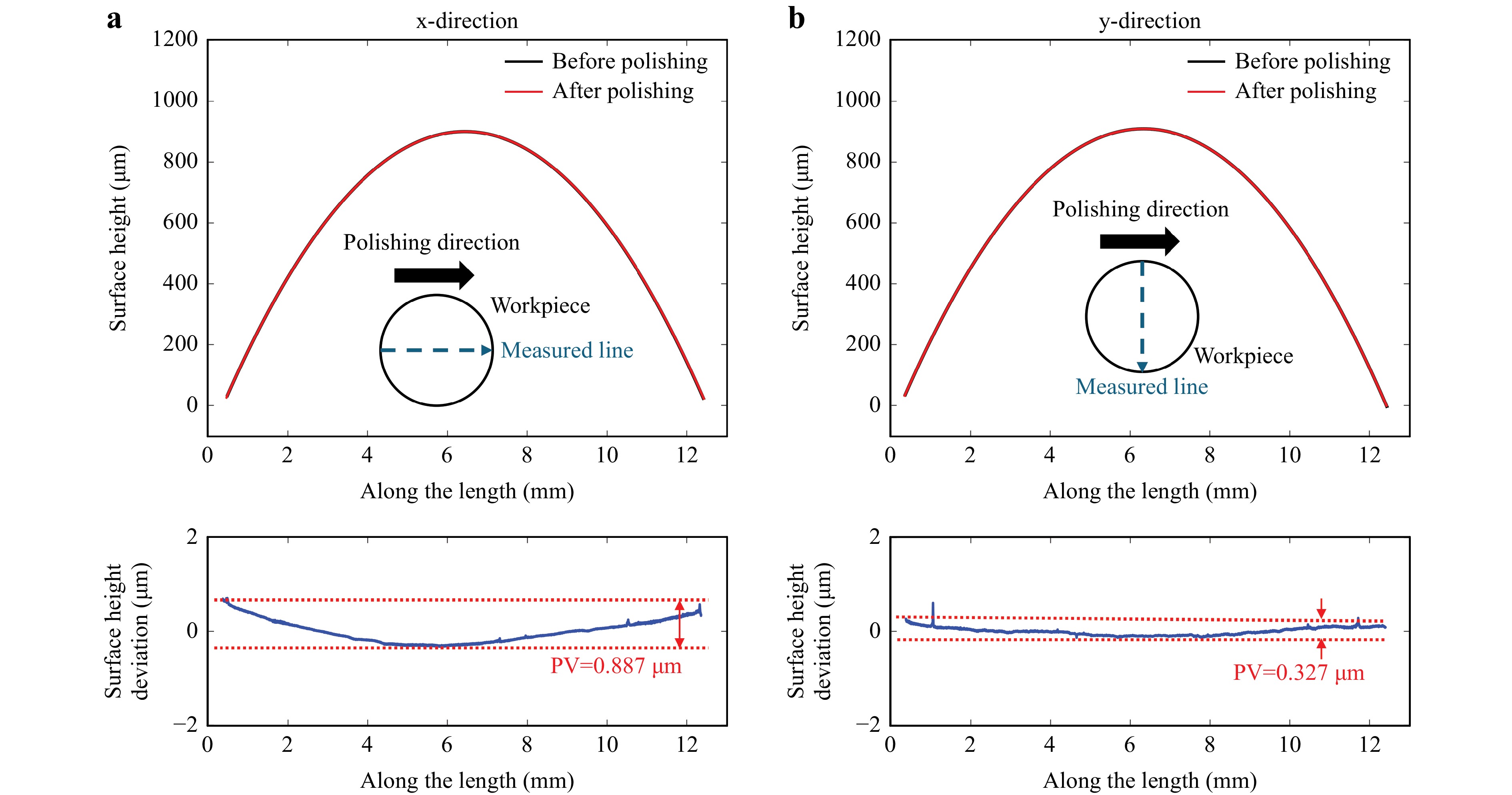
Fig. 10 Form maintainability: a along (x-) and b perpendicular to the (y-) polishing direction of the convex surface.
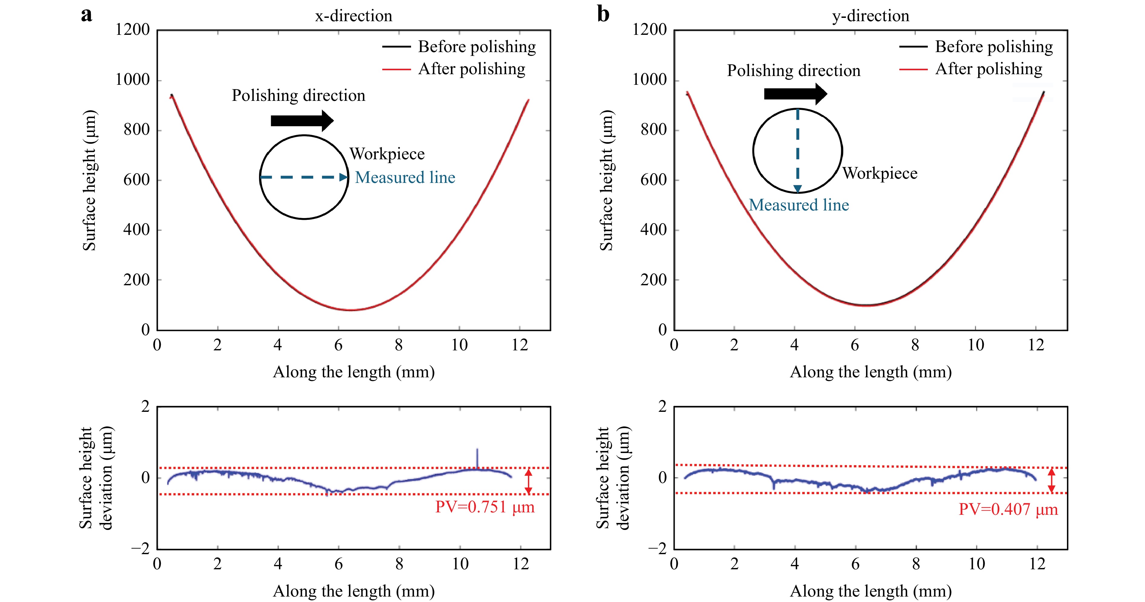
Fig. 11 Form maintainability: a along (x-) and b perpendicular to the (y-) polishing direction of the concave surface.
Fig. 12 compares the measured surface profiles of the hot-embossed structured optical glass before and after polishing, demonstrating that the surface form was sufficiently maintained over the structured region; the peaks and valleys of the surface after polishing conformed to the hot embossed form, and small deviations before polishing were clearly smoothed after the polishing process.
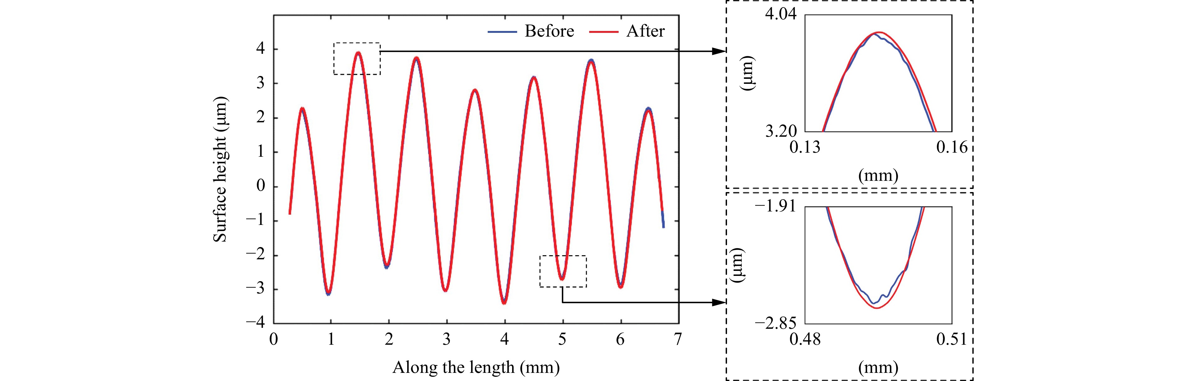
Fig. 12 Comparison of the surface profile of the structured surface.
The results indicated that the surface form of the optical glass can be sufficiently maintained in the MABP within 1 µm, while achieving a superfinished surface roughness, as indicated by an Sa value of 1 nm or less.
In summary, MABP is capable of rapidly polishing convex, concave, and structured optical glass components, while achieving a nanometric surface roughness of approximately 1 nm or less after polishing. The surface-form error of the polished components was well-maintained within 1 µm after polishing, and no subsurface damages were introduced during the MABP. The polishing performance of multiple components was consistent overall, indicating its suitability for the batch polishing of optical glasses.
-
Based on the aforementioned results, the feasibility of the MABP process for the batch nano-polishing of optical glass was demonstrated. Surfaces with a greater roughness apparently require longer polishing durations. Although a surface roughness of approximately 1 nm can be achieved after an extended polishing period, this significantly compromises the accuracy of the surface form owing to the inability to uniformly remove the material across the entire surface during the MABP process because the entire surface is covered by the brush. Consequently, a longer polishing duration resulted in a greater degradation of the form. Furthermore, according to the results of a previous study38, a longer polishing time results in increased material removal, consequently leading to a greater deviation of the form. Therefore, obtaining a smaller surface roughness prior to the MABP process is highly recommended to shorten the polishing time and ensure good maintainability of the surface form, particularly for applications that require a high form accuracy. Further improvements in controlling the material removal in terms of the impingement angle and degrees of freedom will be conducted in the future.
In the current experimental setup, owing to the chamber size and fixture restrictions, only six optical glasses were polished simultaneously, considering the recovery time of the magnetic brushes. By scaling up the chamber size, the number of components that can be simultaneously polished can be further increased.
BK7 is a typical optical glass; the successful polishing of BK7 glass demonstrates the potential of the MABP process for polishing other various optical glasses. The primary variation is likely to be the material removal rate owing to the different hardness levels. Future research will include the polishing of other types of glass, such as fused silica and sapphire optical glasses.
In this study, a diamond polishing slurry with an average particle size of 125 nm was used after conducting the experiments on various fine abrasive slurries. For future MABP applications on rough optical glasses, experiments on other types of polishing slurries with larger particle sizes should be conducted to improve the efficiency of the process.
-
To cope with the increasing demand for superfinished optical components and increase the polishing efficiency, a magnetic-field-assisted batch polishing (MABP) process was proposed. In this study, a series of polishing experiments was conducted on BK7 optical glass to determine the optimal polishing conditions. Finally, a confirmation experiment on the performance of the MABP on a curved surface was presented. The major findings of this study are as follows.
(1) The optimal polishing parameters for optical glass in MABP are as follows: a polishing slurry composed of diamond with a particle size of ~125 nm and 25 wt.% concentration, rotational speed of 500 rpm, and polishing time of 10 min. The polishing experiments demonstrated that a lapped BK7 optical glass with an initial surface roughness, as indicated by the arithmetic mean height (Sa), was 27 nm, which decreased to 0.7 nm after polishing by using the optimal parameters, indicating an improvement of 97%.
(2) The sufficient performance of the MABP in polishing multiple curved and structured surface optical glasses was demonstrated. After MABP polishing, the surface roughness was improved to the nanometric level and the form accuracy was maintained within 1 µm, enabling an efficient and accurate batch polishing option for optical glass.
(3) The material removal rate of the MABP in optical glass polishing was approximately 167 nm/min at a rotation speed of 500 rpm using the current prototype. In addition, no evident subsurface damage was observed after polishing.
-
Fig. 13a presents a schematic diagram of the MABP process, in which at least two pairs of N52-grade permanent magnets were installed on a rotating plate to generate a rotating magnetic field with a strength of approximately 0.4−0.5T in the working area. The magnetic polishing medium was poured into an annular chamber before polishing, and two or more brushes were generated under the effect of the magnetic field. The magnetic polishing media was a mixture of micrometer-scale carbonyl iron powder (CIP) (average particle size of approximately 2 µm), polishing slurry with nanometer-scale diamond abrasives (average particle size of 125 nm), and deionized water that acts as the base carrier fluid. Moreover, rotating the magnets drives the magnetic brushes to rotate inside the chamber. A batch of optical components was installed on the fixtures inside the chamber (Fig. 13a), and the fixtures were connected to the lid. During polishing, the magnetic brush continuously impinged the optical components, leading to a micro-nanometric material removal for polishing purposes.
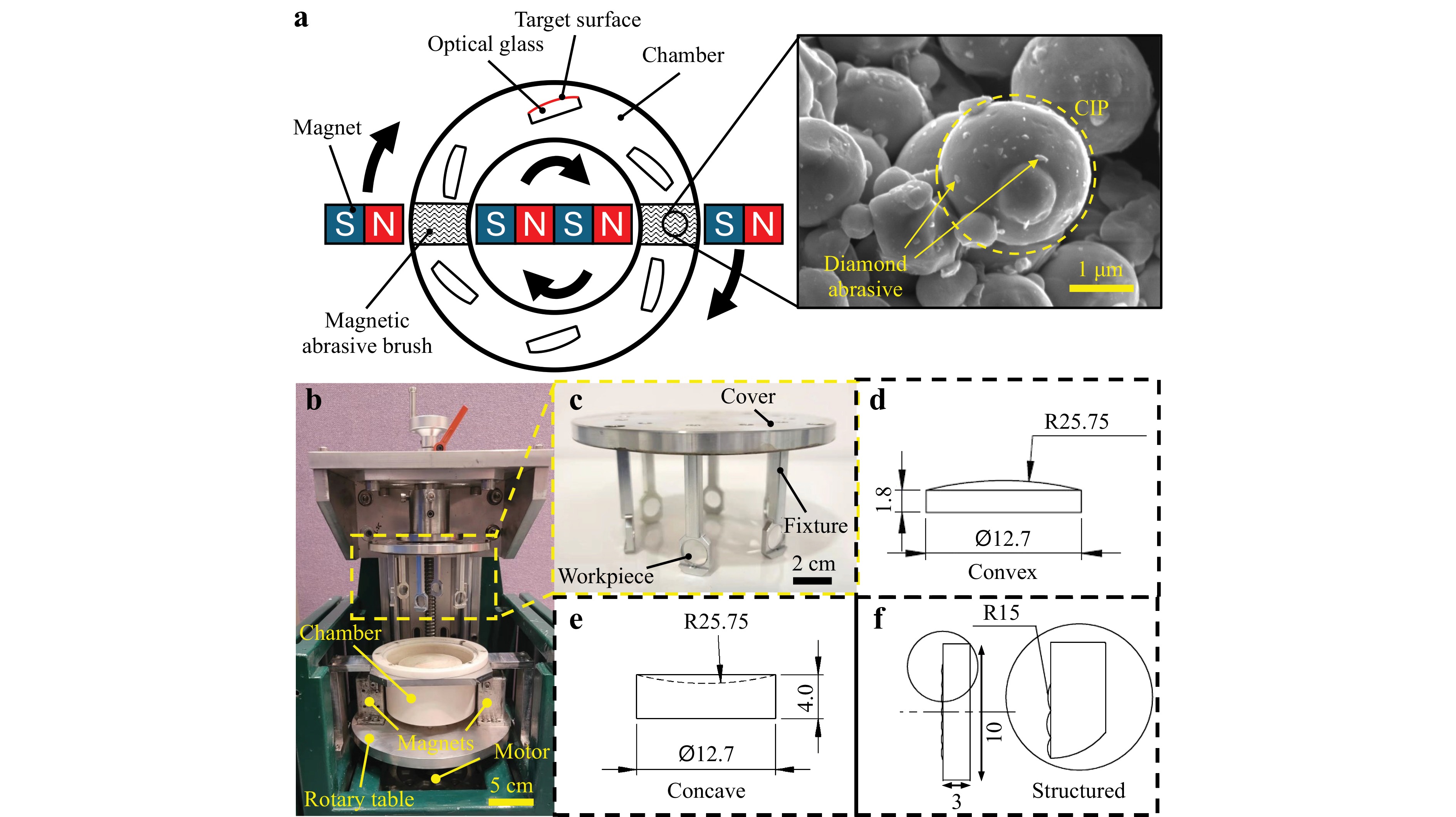
Fig. 13 Experimental setup of MABP. a Schematic diagram, b MABP machine, c workpiece mounting, d convex lens, e concave lens, and f structured workpiece dimension.
An experimental prototype of the MABP machine was built, as shown in Fig. 13b−f, in which six optical components were simultaneously polished, as shown in the top-right part of Fig. 13c. The number of workpieces simultaneously polished can be increased by changing the design of the cover, and be significantly larger by scaling up the prototype. The workpiece was placed in the middle of the magnet in the vertical direction to ensure a uniform brush coverage.
-
In this study, flat, convex, and concave BK7 optical glasses with a diameter of 12.7 mm and radius of curvature of 25.75 mm were used as specimens, as shown in Fig. 14. Before MABP polishing, all the optical glasses were lapped using #2500 silicon carbide sandpaper, resulting in a rough surface with an arithmetic mean height (Sa) of approximately 25 nm. Three groups of experiments were conducted to examine the performance of MABP in optical glass polishing, as shown in Table 1.
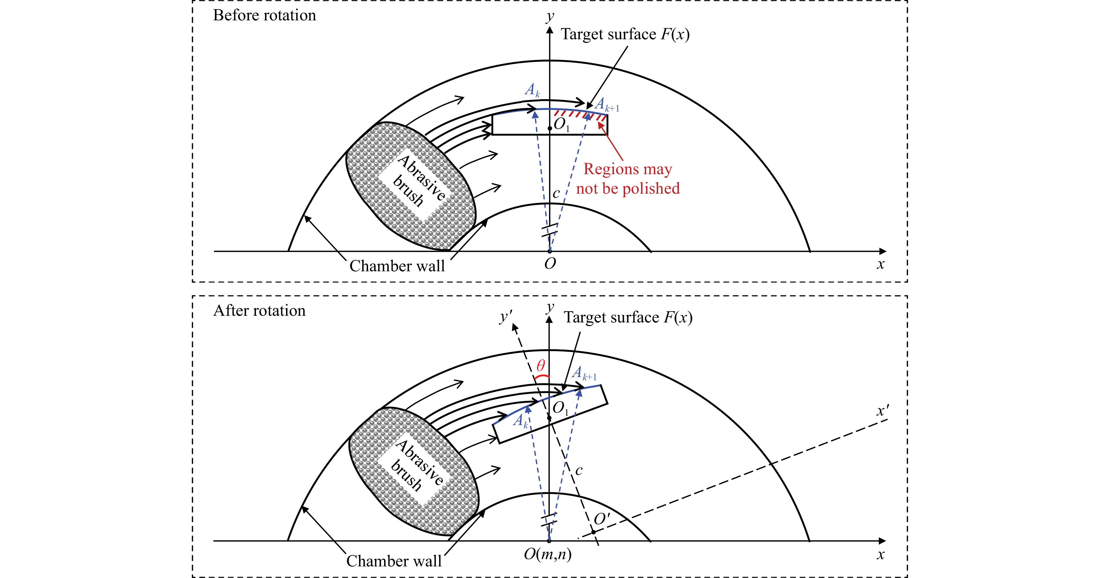
Fig. 14 Determining the minimum impingement angle for an improved polishing uniformity.
The performance of different types of polishing slurries along with the polishing time for glass polishing were analyzed in the first group of experiments. Three types of polishing slurries were prepared using different abrasive materials and particle sizes, as listed in Table 2. In this experiment, the size of the CIP and weight concentration of the abrasive slurry were maintained at an average of 2 μm and 25 wt.%, respectively. Different types of polishing slurries were mixed with fixed amounts of CIP to form magnetic abrasives. Measurements were obtained every 5 min of polishing for 20 min to observe the change in the surface roughness with different types of slurries. Thus, to determine a suitable polishing slurry with a better performance for glass polishing, the experimental details are listed in Table 1. The second group of experiments focused on the effect of the rotational speed. After determining the abrasive slurry type from the previous experiment group, another group of experiments was conducted to examine the polishing performance of the polishing slurry under three different rotational speeds. Finally, a confirmation experiment was conducted based on the results from the two aforementioned groups of experiments to validate the performance of the MABP on glass polishing with curved and complex geometries.
Polishing Slurry Abrasive material Average abrasive size (μm) A Diamond 0.125 B Cerium oxide 0.55 C Diamond 0.5 Table 2. Types of polishing slurry
-
The impingement angle is a critical parameter that affects the polishing efficiency and uniformity, as indicated in previous studies38–40. To ensure effective polishing over a curved surface, the minimum impinging angle must be determined. Fig. 14 presents a geometric illustration of the process for determining the impinging angle. When the convex workpiece is set at an impinging angle of 0°, the contact between the rotating magnetic abrasive brush and curved surface may not be significant over the entire surface because a certain amount of the abrasives are retained on the edge of the workpiece. By increasing the impinging angle by $ \theta $, the entire curved surface can be reached by the rotating abrasive brush along the path.
As demonstrated in the illustration, the machining rotation center O was set as the origin of the coordinate system, and O1 was the rotation center of the curved workpiece surface $ F\left(x\right) $. Furthermore, $ {A}_{k}(x,y) $ indicates a point on the workpiece surface and $ {A}_{k+1}(x,y) $ is a point next to it. To ensure that the magnetic abrasive brush can access any point on the curve of the workpiece surface $ F\left(x\right) $, $ {A}_{k}(x,y) $ must be in the projection area of the brush; that is, distance $ O{A}_{k+1} $ must be greater than $ {OA}_{k} $. This can be achieved by rotating the workpiece around the rotation center $ {O}_{1} $, increasing the impingement angle by $ \theta $, as shown in Fig. 3. The distance $ O{O}_{1} $ is denoted as $ c $. After the rotation, the origin $ O(m,n) $ relative to the new coordinate system $ x'O'y' $ can be expressed as follows:
$$ \left\{\begin{array}{l}m=-csin\theta \\ n=c(1-cos\theta )\end{array}\right.\left(1\right) $$ (1) Thus, the square of the distance between the abrasive rotation center and point A $ {\left|O'{A}_{k}\right|}^{2} $, which is defined as $ D\left(x\right) $, can be expressed as follows:
$$ D\left(x\right)={(x-m)}^{2}+{(F\left(x\right)-n)}^{2}\left(2\right) $$ (2) To obtain the minimum impinging angle required for a uniform polishing over a curved surface, $ D\left({x}_{i}\right) $ and $ D\left({x}_{i+1}\right) $ must be obtained and compared according to Eqs. 1, 2 at an initial impinging angle of $ \theta $ = 0. Subsequently, $ \theta $ can be slightly increased and the process above can be repeated until $ D\left({x}_{i}\right) < D\left({x}_{i+1}\right) $, with an increasing abscissa $ x $ for the curved surface $ F\left(x\right) $, thus obtaining the following:
$$ \begin{array}{c}{({x}_{i}-m)}^{2}+{(F\left({x}_{i}\right)-n)}^{2} < {({x}_{i+1}-m)}^{2}+{(F\left({x}_{i+1}\right)-n)}^{2}\\\left({x}_{i} < {x}_{i+1}\right) \end{array}$$ (3) When $ D\left({x}_{i}\right) < D\left({x}_{i+1}\right) $ is achieved at $ \theta $, the minimal impinging angle can be determined.
In the experimental setup above, $ O{O}_{1} $ was 42 mm, the diameter of the workpiece was 12.7 mm, and the convex and concave curvature of the surface was 25.75 mm. The calculated minimum angles for the flat, convex, and concave R25.75-mm component were 8.7°, 6.1°, and 23.8°, respectively. The impingement angle in the MABP experimental setup was controlled by using an increment of 15°; thus, 15° was selected for polishing the flat, convex, and structured surfaces, and 30° was selected for polishing the concave surfaces.
-
In this study, the surface roughness (Sa, Sz) before and after the polishing experiments was measured by a Zygo Nexview white light interferometer every 5 minutes; five measurements with a spot size of 213 × 213 µm were obtained at random positions and averaged for each sample. The profiles of the surface form of the convex and concave lenses in both the x- and y-directions were measured using a Talysurf PGI1240 profilometer; a total length of 12 mm was measured with a Gaussian filter, and the cutoff length ($ {L}_{C} $) was 0.08 mm. The workpieces were bathed in alcohol and cleaned using an ultrasonic cleaning machine for 10 min before the measurements. Scanning electron microscopy (SEM) images were obtained using TESCAN VEGA3 after gold sputtering to observe the surface texture, and the Park Systems XE70 atomic force microscopy (AFM) was applied to evaluate the surface topography before and after the polishing experiments; a 20 × 20 µm area was measured with a scan rate of 0.25 Hz. The depth of the material removal of the optimal polishing parameters for the optical glass was measured by the Talysurf PGI1240 profilometer; a piece of flat optical glass with a partial surface covered by tape was polished and then measured along both unpolished and polished regions.
-
The work described in this study was mainly supported by grants from the Research Grants Council of the Government of the Hong Kong Special Administrative Region, China (Project No. 15203620), the Research and Innovation Office of The Hong Kong Polytechnic University (Project codes: BBXN and BBX5), and research studentships (project code: RH3Y). The authors would also like to express their sincere thanks for the funding support from the State Key Laboratories in Hong Kong from the Innovation and Technology Commission (ITC) of the Government of the Hong Kong Special Administrative Region (HKSAR), China.
Magnetic field-assisted batch polishing method for the mass production of precision optical glass components
-
Yee Man Loh
 ,
, -
Chunjin Wang*, ,
,
- Rui Gao,
- Lai Ting Ho,
-
Chi Fai Cheung*, ,
- Light: Advanced Manufacturing 5, Article number: (2024)
- Received: 20 December 2023
- Revised: 08 March 2024
- Accepted: 12 March 2024 Published online: 26 August 2024
doi: https://doi.org/10.37188/lam.2024.028
Abstract: The demand for optical glass has been rapidly increasing in various industries, where an ultra-smooth surface and form accuracy are critical for the functional elements of the applications. To meet the high surface-quality requirements, a polishing process is usually adopted to finish the optical glass surface to ensure an ultra-smooth surface and eliminate sub-surface damage. However, current ultra-precision polishing processes normally polish workpieces individually, leading to a low production efficiency and high polishing costs. Current mass-finishing methods cannot be used for optical glasses. Therefore, magnetic-field-assisted batch polishing (MABP) was proposed in this study to overcome this research gap and provide an efficient and cost-effective method for industrial use. A series of polishing experiments were conducted on typical optical components under different polishing parameters to evaluate the polishing performance of MABP on optical glasses. The results demonstrated that MABP is an efficient method to simultaneously polish multiple lenses while achieving a surface roughness, indicated by the arithmetic mean height (Sa), of 0.7 nm and maintained a sub-micrometer surface form for all the workpieces. In addition, no apparent sub-surface damage was observed, indicating the significant potential for the high-quality rapid polishing of optical glasses. The proposed method is highly competitive compared to the current optical polishing methods, which has the potential to revolutionize the polishing process for small optics.
Research Summary
Surface finishing: Simultaneous surface nanofinishing of optical glass
The demand for optical glass has been rapidly increasing in various industries where ultra-smooth surface and accurate shape are critical for the functional elements of the application. Efficient and effective surface finishing processes are crucial to meet the increasing demand. Chunjin Wang from the Hong Kong Polytechnic University and colleagues now report a novel and cost-effective method for bulk processing of optical glass components. The surface integrity of the simultaneously polished optical glass meets nano-scale surface roughness. The team demonstrated its application in several geometries and applications that proved its potential to revolutionize the polishing process for small optics.
Rights and permissions
Open Access This article is licensed under a Creative Commons Attribution 4.0 International License, which permits use, sharing, adaptation, distribution and reproduction in any medium or format, as long as you give appropriate credit to the original author(s) and the source, provide a link to the Creative Commons license, and indicate if changes were made. The images or other third party material in this article are included in the article′s Creative Commons license, unless indicated otherwise in a credit line to the material. If material is not included in the article′s Creative Commons license and your intended use is not permitted by statutory regulation or exceeds the permitted use, you will need to obtain permission directly from the copyright holder. To view a copy of this license, visit http://creativecommons.org/licenses/by/4.0/.

 DownLoad: