


-
Optical micro/nanofibers (MNFs) drawn from standard silica fibers have been widely used as a miniature fiber-optic platform for manipulating optical fields with great versatility1-3. Benefitting from their favorable optical properties including low waveguiding loss, strong evanescent fields, tight optical confinement, high power transmission, and excellent compatibility with standard optical fibers2-5, these MNFs have been extensively studied for applications ranging from optical couplers6-8, nonlinear optics9-12, optical sensors13-16, atom optics17-19, to fiber lasers20,21 and opto-mechanics22-25. As the structural parameters (waist diameter, uniform length, and tapering profile) of an MNF are subject to different demands in various application scenarios2,3,26, a number of MNF fabrication and geometry control techniques have been developed27-32, and MNFs with ultrahigh qualities (e.g., ultra-low loss33, ultra-high-precision diameter control30,31,34) have been realized. However, all these techniques focus on the single-MNF fabrication, that is, drawing one MNF at a time.
In recent years, MNF arrays or multiple MNFs with identical geometries have been attracting more and more attention. Starting from near-field coupling and waveguiding field configuration in two parallel MNFs35-38, now MNF-array structures have been reported for a variety of applications from efficient single-photon collection38, compact variable fiber couplers39, stable atom traps40, topological phase transitions41 to high-sensitivity and spatial-resolved optical sensors36,42,43, and high-resolution compact spectrometers44. Moreover, for future industrial applications, high-yield fabrication of MNFs with identical parameters is always desired for large-scale manufacturing MNF-based devices. However, so far, almost all MNF arrays are fabricated with single-MNF fabrication techniques42,44. Although the current single-MNF fabrication technique is relatively mature, considering that the low drawing speed (typically 0.1 mm/s) requires a long-term high-precision control and highly stable heating condition, it remains complicated and time-consuming to fabricate a MNF array consisting of multiple MNFs with same geometric parameters.
Here, we demonstrate a parallel-fabrication technique for simultaneously drawing multiple high-quality MNFs in a single step. By investigating and optimizing the drawing force and subsequently the drawing temperature for MNF array fabrication, we have designed and developed a wide-field electric heater that can offer a uniform-temperature distribution (up to 1300 °C) in a 6.2-mm-wide heating zone, and have successfully drawn multiple (up to 20) MNFs with high consistency. Meanwhile, the real-time optical transmittance of each MNF has been measured for in-situ monitoring the drawing process. For typical MNF arrays with diameters from 520 nm to 1.22 μm, the measured optical transmittances of all the as-drawn MNFs exceed 96.7% at 1550-nm wavelength, with a diameter deviation within 5%. Compared with previous single-MNF fabrication techniques, our parallel-fabrication technique, realized by optimizing the heating and drawing conditions, presents a high-yield approach for simultaneously fabricating multiple MNFs with high diameter uniformity and optical transmittance.
-
Similar to that in drawing a standard glass optical fiber45-47, tensile force and working temperature are critical to yield high-quality optical MNFs. However, unlike that in the standard fiber fabrication, in which the drawing speed can be as high as tens of meters per second (e.g., 25 m/s48), a high-transmittance MNF is typically drawn at a much lower speed (e.g., 0.1 mm/s) to facilitate precise shaping of the taper profile to avoid loss from mode transition.
Previously, the tensile force in drawing single MNFs or fiber tapers has been studied49-52. Here, the required tensile force increases proportionally with the number of MNFs in the parallel fabrication, and thus may also become an issue to be considered. Fig. 1a shows the schematic diagram of the tensile force measurement system, and the detailed system setup and measurement methods can be found in Materials and Methods. Fig. 1b gives the dependence of measured tensile force on the tapering time at typical drawing temperatures from 1140 °C to 1300 °C53,54, with a fixed drawing speed of 0.1 mm/s. During the drawing process, due to the temperature-dependent viscoelasticity of glass45,55-57 and the continuously-decreasing diameter of the MNF, the tensile force increases first to the maximum, and then decreases exponentially with tapering time (quadratically with the MNF diameter, see Fig. 1c).
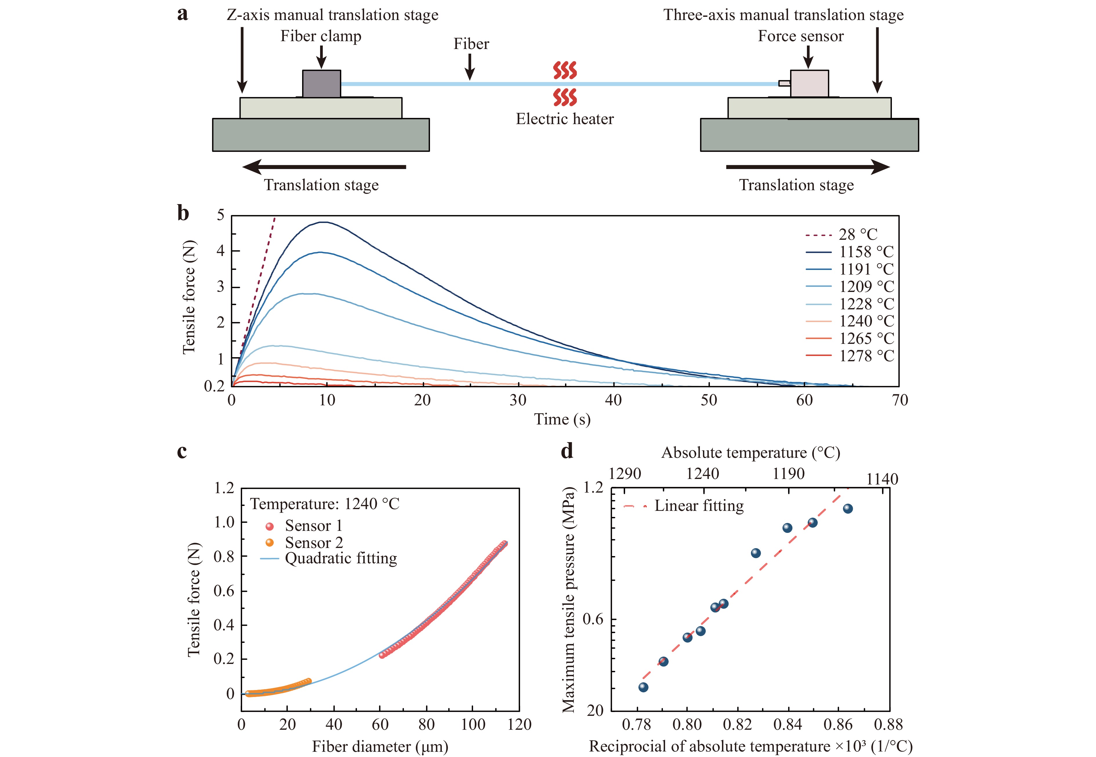
Fig. 1 Tensile force during the tapering process of a single MNF. a schematic diagram of MNF tensile force measurement system; b tensile force-time curves at different temperatures in the fiber tapering process; c tensile force-waist diameter curve at 1240 °C. The red data is measured by a large-range force sensor (ALIYIQI, HF-20), while the orange data is measured by a high-precision force sensor (ME, KD18s±0.1 N). The blue curve is the quadratic function fitted to all the data; d relationship between the maximum tensile pressure and temperature. The dashed line is the linear fit of the maximum tensile pressure and reciprocal of the temperature in the exponential coordinate.
In the parallel fabrication, the maximum tensile force is a crucial consideration. For example, in Fig.1b, when the temperature increases from 1158 °C to 1278 °C, the maximum tensile force for drawing a 20× array of MNFs decreases from 96 N (4.8 N per MNF) to 7.6 N (0.38 N per MNF). The relatively high temperature, and consequently small tensile force are preferred for ensuring the high precision of the mechanical system, such as preventing slipping between the fibers and the clamps, and avoiding over-load operation of the translation stages (e.g., <100 N for Newport M-ILS300LM-S used in this work) for maintaining long-term high precision. On the other hand, excessively high temperature and consequently low viscosity will increase difficulty in controlling the morphology of the tapering region of MNFs. In our system, after optimization, we select a tapering temperature ranging from 1240 °C to 1250 °C for parallel drawing of a 20× fiber array, corresponding to a maximum tensile force of about 15.8 N (at 1250 °C) to 17.4 N (at 1240 °C) (see Fig. S1). By extrapolating the tensile force in Fig.1c, optimizing the fabrication parameters (e.g., tensile force and tapering temperature) for tapering fibers with larger diameters (e.g., > 125 μm) is possible.
In addition, from Fig. 1b, the temperature-dependent maximum tensile pressure can also be obtained (Fig. 1d). The approximately linear dependence of the pressure on the reciprocal of the temperature in the exponential coordinate, agrees well with those reported in drawing standard optical fibers45,46.
-
In the initial pulling stage, in order to prevent adjacent glass fibers from sticking together at high temperature, the fibers are arranged in a parallel array at a distance of one fiber apart, thus, a 20× MNF array has a transverse width of about 5 mm. Therefore, compared to the single-MNF drawing case, the parallel fabrication of MNFs requires a high-temperature (e.g., 1250 °C) source that has a much wider zone with uniform-temperature distribution perpendicular to the fiber length, while keeping a similar temperature gradient along the fiber length as the single-MNF case. However, to our knowledge such a heater is not yet commercially available.
To satisfy the heating conditions, we design a home-made electric heater. As shown in Fig. 2a, the main heating source is an electric heating wire (FeCrAl alloy) helically wound around two parallel ceramic tubes with a slit size of 3 mm. For thermal insulation, the heater is enclosed by block-shaped polycrystalline mullite fiber boards (not shown here, see more details in Fig. S2). When a proper current is applied on the heating wire, the desired high-temperature field can be generated in the slit. To reduce its oxidation and nitridation, the heating wire is protected by a positive-pressure argon environment (see more details in Materials and Methods). Fig. 2b gives a measured temperature distribution on the central plane of the slit (X-Y plane in Fig. 2a) with a current of 8.4 A. It shows that, a 6.2-mm-length uniform temperature distribution (Tmax = 1243 °C, ∆T < 0.5 °C) along the Y direction is generated (Fig. 2c), with a sharp temperature drop along the X direction.
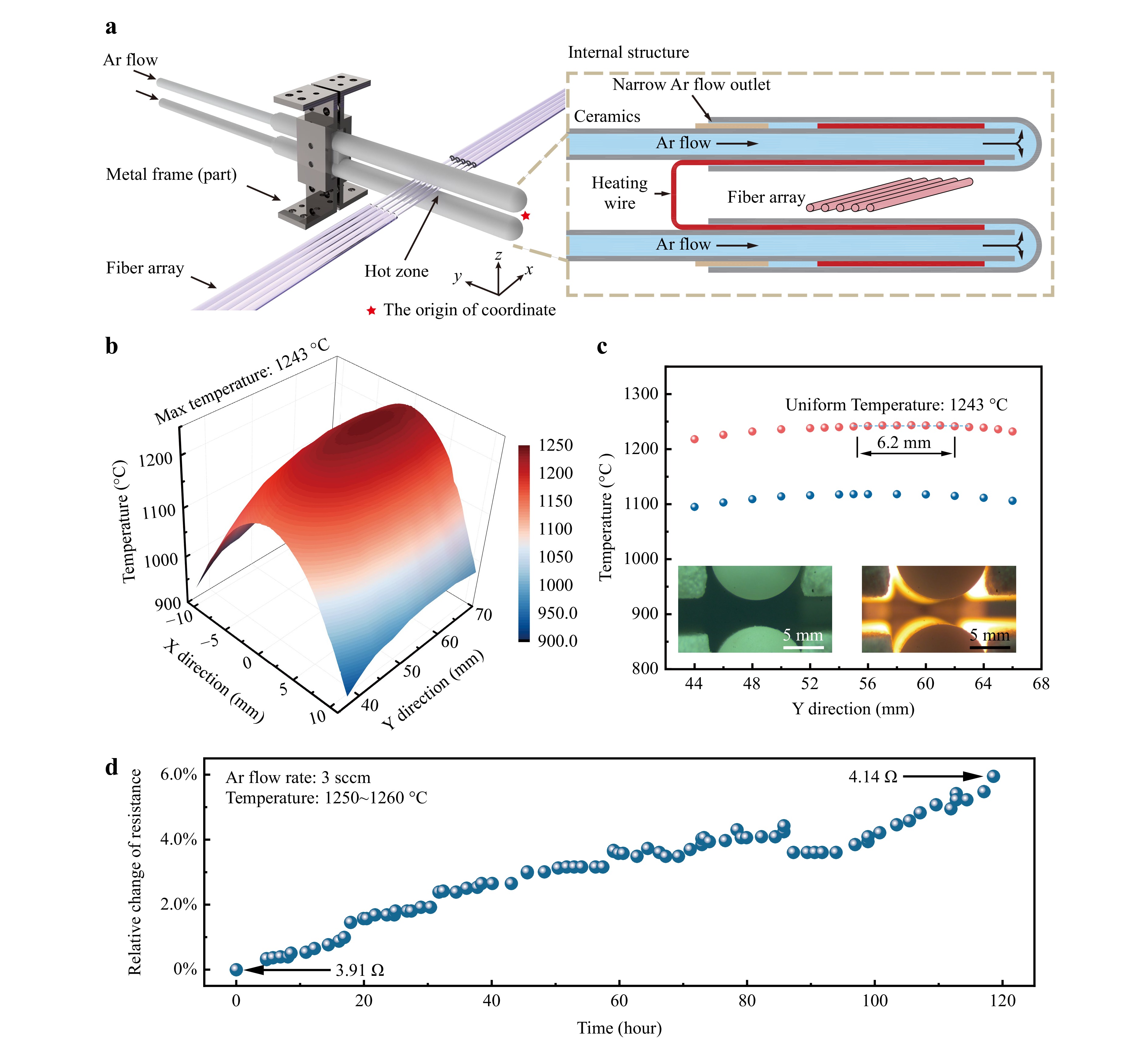
Fig. 2 Fundamental structure and characteristics of the electric heater. a schematic diagram of the electric heater. The heating source, that consists of a heating wire (Kanthal, FeCrAl) and ceramic components (e.g., ceramic tubes and sleeves), is supported by the metal frame (6061 aluminum alloy). The block diagram presents a simplified internal structure of the heater. Blue part: Argon gas, red part: heating wire, brown part: ceramic support ring, grey part: ceramic tube. The two electric terminals of heating wire pass through the inner holes of the two ceramic tubes (one from the top and one from the bottom), and are connected to copper wires, which are connected to an external power source through the glass adaptors (see Fig. S2); b temperature distribution of the thermal field at the central plane (X-Y plane in Fig. 2a) of the slit; c Y-direction temperature distribution of the heater at the central plane of the slit. Pink dots and blue dots are the temperature distribution with the uniform temperatures of 1243 °C and 1117 °C, respectively. Insets, optical photographs of the electric heater at room temperature (23 °C) and working temperature (1243 °C); d long-term-stability test of the heater.
The long-term-stability test of the heater is also investigated. As shown in Fig. 2d, under a constant current of 8.6 A, the measured maximum temperature gradually increases with the operation time, which can be attributed to the increasing resistance of the heating wire (e.g., from 3.91 to 4.14 Ω after 120 hours), and can be compensated by reducing the current accordingly. When operating at 1250 °C, the measured lifespan of the heater is typically more than 120 hours, close to those of commercial heaters (e.g., NTT CMH-7019) for single-MNF fabrication.
-
Fig. 3a schematically illustrates the experimental setup for parallel fabrication, which is similar to our previous single-MNF pulling system in principle30,34, except that here the electric heater, the mechanical pulling components and the optical measurement components are designed for multiple fibers (see Fig. S3 for a photograph). The electric heater is fixed on a translation stage for adjusting the relative position between the heater and the fiber array. The fiber clamps (Fig. S4) can fasten up to 20 parallel fibers with a center spacing of around 250 μm (Fig. 3b). The tapering region of the fiber array is in-situ monitored by two cameras from the vertical and horizontal directions, respectively. To monitor the real-time transmittance during the drawing process, a 1550-nm-wavelength light is splitted and coupled into 20 fibers, transmitted through the tapered fibers, and then collected by a 20-channel photodetector (more details in Materials and Methods).
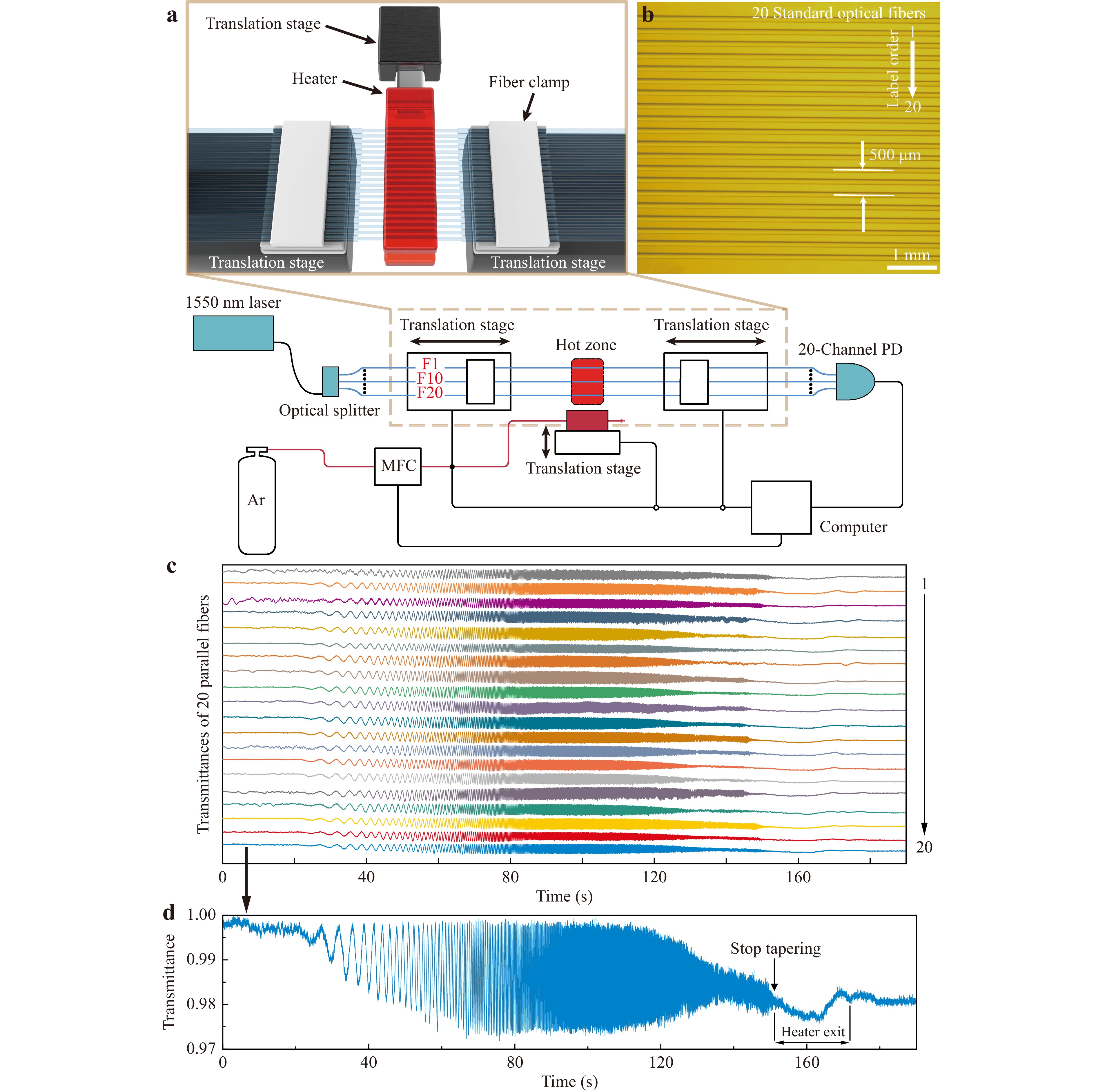
Fig. 3 Parallel-fabrication system. a schematic diagram of the parallel-fabrication system for MNFs. The system consists of a home-made electric heater (the red part in the middle), three translation stages (two for fiber tapering, one for heater movement), optical measurement components and a computer. Blue lines represent the fibers and red lines represent the argon gas circuit. Ar, argon gas; PD, photodetector; F, fiber; MFC, mass flow controller; b optical image of 20 parallel fibers. These 20 bare optical fibers are fixed on fiber clamps, with a center spacing of about 250 μm; c transmittance curves at a wavelength of 1550 nm as functions of time during the tapering process; d normalized transmittance of the 20th MNF.
Experimentally, the aligned fibers (Corning SMF-28e) are preheated for about 120 seconds at 1240 °C, and then drawn by translation stages that move oppositely at velocities of 0.1 mm/s. Meanwhile, the transmittance of each fiber is measured and recorded at a frequency of 100 Hz, and displayed for real-time monitoring. For example, Fig. 3c shows time-dependent transmittances of 20 fibers at a wavelength of 1550 nm. It can be observed that the multimode-induced oscillation for each fiber, which is directly related to the diameter of fibers, starts almost simultaneously and is supressed at approximately the same time, indicating a nearly identical drawing environment of the fibers. For reference, an enlarged transmittance curve of the 20th MNF is shown in Fig. 3d, and a video of typical tapering process can be found in Movie S1. Additionally, fiber arrays can be conveniently dismounted and transferred without fracture by using specially designed transfer tools (see for example, Fig. S5).
-
The optical image of a set of 20 parallel MNFs, corresponding to the transmittance curves (Fig. 3c) mentioned above, is shown in Fig. 4a. The accurate diameters of the MNFs are measured by scanning electron microscopy (SEM). Fig. 4b shows SEM images of MNFs with the maximum (1.27 μm) and minimum (1.19 μm) diameters within this set of parallel MNFs. Fig. 4c shows the diameters and transmittances of all the 20 MNFs. It can be seen that the diameters are ranging from 1.19 μm to 1.27 μm, with an average diameter of 1.22 μm and a maximum deviation of less than 5%. All the MNFs exhibit a transmittance higher than 97.2%, with the maximum transmittance reaching 99.7%. The excellent diameter uniformity and high transmittance can be maintained for the fabrication of MNF arrays with an average diameter down to about 500 nm, which can be attributed to the high stability of the heating and stretching conditions during the drawing process. For example, Fig. 4d shows the measured diameter and transmittance of an as-fabricated 10× MNF array with a MNF diameter of about 530 nm. Centered around an average diameter of 529.4 nm, the diameters of this set of MNFs are distributed between 519.2 nm and 552.7 nm, with a maximum diameter deviation within 5% and a lowest transmittance of 96.7%. For reference, a typical tapering process of such MNF arrays can be found in Movie. S2. Additionally, fabricating MNF arrays with smaller spacings (e.g., < 125 μm) or large-length uniform waists (e.g., > 10 cm) is challenging with our current parallel-fabrication system. To fabricate such MNF arrays, an improved design for aligning “preform fibers” more densely or a scanning electric heater may be desired.
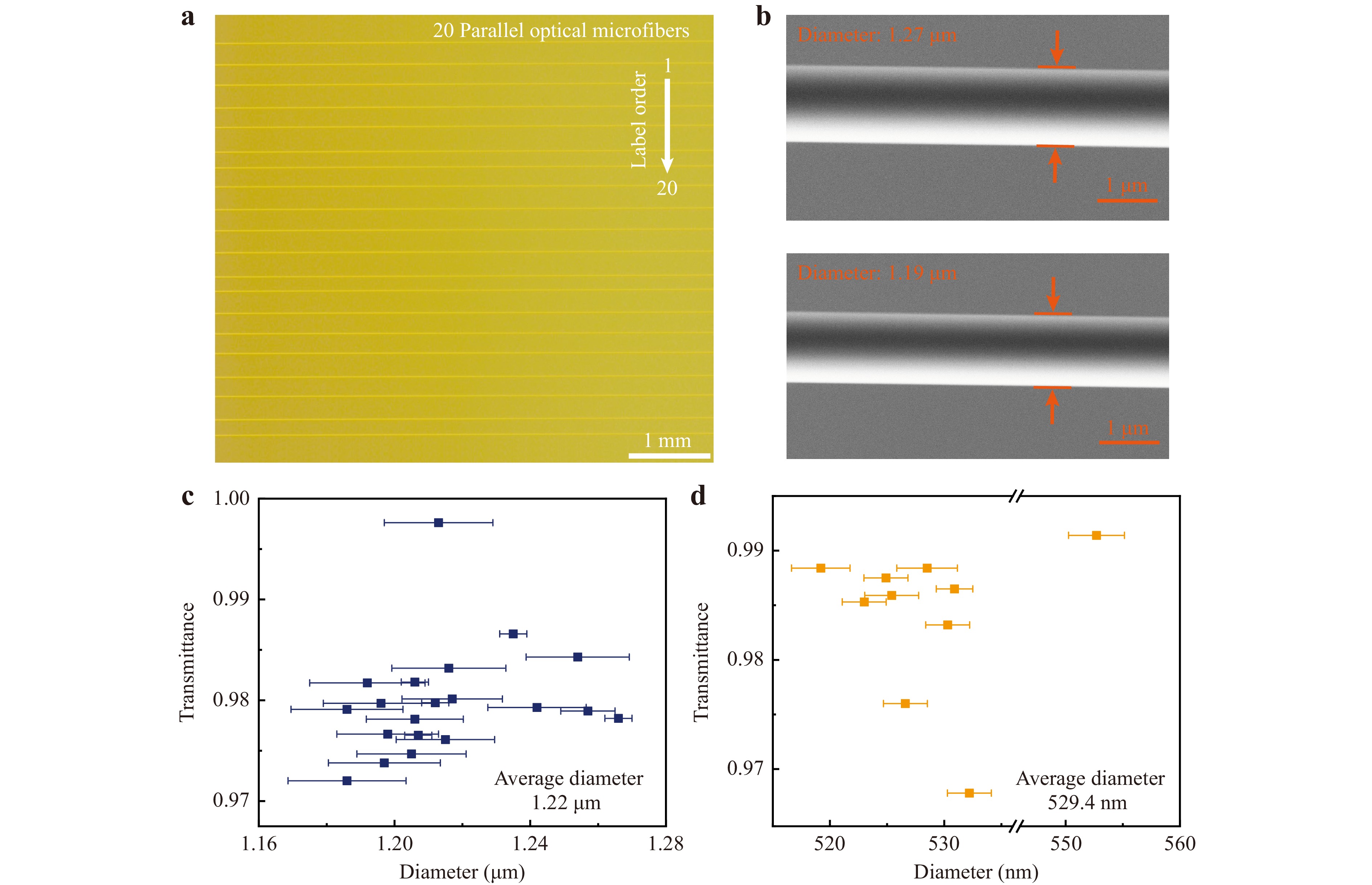
Fig. 4 Characteristics of parallel MNFs. a optical image of 20 MNFs in parallel; b SEM images of MNFs with the maximum (1.27 μm) and minimum (1.19 μm) diameters within 20 parallel MNFs; c diameters and transmittances of 20 parallel MNFs. The diameters are among 1.19 μm to 1.27 μm. The transmittance of each MNF is obtained as the ratio of transmitted power after and before the drawing process, and ranges from 97.2% to 99.7%; d diameters and transmittances of 10 parallel MNFs. The diameters are distributed between 519.2 nm and 552.7 nm, and the transmittances range from 96.7% to 99.1%. The error bars are the tolerances of multiple measurements.
-
In summary, we have demonstrated a parallel-fabrication approach to simultaneously drawing multiple (up to 20) silica MNFs with high repeatability. Relying on a detailed investigation on the dependence of the tensile force on different tapering temperatures, we optimize the tapering temperature for fabrication of parallel MNFs and have accordingly designed a wide-zone electric heater with a 6.2-mm-width uniform-temperature field. By incorporating the wide-zone electric heater, multi-channel mechanical pulling components and the optical measurement components for multiple fiber drawing, we have fabricated MNF arrays with fiber diameters down to ~500 nm. The measured optical transmittances of these MNFs are typically higher than 96.7% at 1550-nm wavelength, with a diameter deviation within 5%. This parallel-fabrication approach can be extended to fabricate fiber arrays with more than 20 fibers. Since MNF arrays are desired in compact variable fiber couplers39, high-resolution compact spectrometers44, high-sensitivity and spatial-resolved optical sensors36,42,43, single-photon collection38, topological phase transitions41 and MNF-assisted high-efficiency broadband fiber-to-chip coupling8, the possibility to fabricate MNF arrays with the excellent diameter uniformity and high transmittance paves a way towards high-yield fabrication of MNFs, which may find broad applications from MNF-based passive optical components, optical sensors, optical manipulation to topological optics and fiber-to-chip interconnection.
-
The tensile force measurement system is shown in Fig. 1a. A 12.5-cm-length standard optical fiber (Corning SMF-28e) with around 6-cm-length coating peered off was used to measure the tensile force of taper-drawn biconical fiber during the drawing process. The both ends of the optical fiber were fixed to a fiber clamp and a force sensor (ALIYIQI, HF-20) on both sides, respectively. The optical fiber, the clamp, and the force sensor were along the same horizontal line by adjusting a Z-axis manual translation stage (DHC, GCM-V25M) and a three-axis manual translation stage (OMTOOLS, OMYE62D) on both sides. The electric heater was used to generate a constant hot zone and heat the fiber to a certain temperature (1140 °C ~ 1300 °C). After the fiber reached a thermally stable state, two translation stages (Newport M-IMS500LM-S) began to taper it at a controlled speed of 0.1 mm/s, respectively, and the force sensor simultaneously measured the tension data during the whole drawing process.
-
A 1-mm-diameter helically wound heating wire (Kanthal, FeCrAl) with a mean coil diameter of 6 mm was used as the heating source. The length of the heating wire can be customized according to the required heating range. For example, a heating wire with a spiral length of 8 cm (40 turns) and a resistance of about 4 Ω was chosen for the parallel fabrication of 20 MNFs.
The heating wire was supported by two parallel ceramic tubes, as the red part in the internal structure (the right panel of Fig. 2a). As mentioned in Section Electric heating scheme, the heating source was wrapped by block-shaped polycrystalline mullite fiber boards (see Fig. S2) and can generate high temperature in the 3 mm-wide slit between the ceramic sleeves when energized. Typically, this electric heating source was capable of operating reliably within a temperature range below 1300 °C and the required voltage did not exceed 40 V. Considering the fact that the heating wire has obvious corrosion reaction with the oxygen and nitrogen in the surrounding air under high-temperature circumstances58,59, e.g., 2Cr + N2 = 2CrN (800 °C ~ 1400 °C), an argon gas environment around the heating wire was applied to reduce its aging rate. As illustrated in Fig. 2a, the ceramic tubes and the ceramic sleeves that supported and protected the heating wire also served to guide the argon gas, where the argon gas flowed through the inner cavity of the ceramic tubes, traversed through the interlayer, and ultimately exited. The notched ceramic rings (brown part in internal structure, Fig. 2a) were positioned at the end of the sleeves, complemented by a few sealants, to effectively minimize the egresses of the gas flow while providing structural support. The flow rate was precisely controlled to 3 sccm by two flow controllers (Sevenstar, CS100), respectively.
-
To monitor the transmittance of optical fiber arrays, a 1550-nm-wavelength light (Connet Laser, VLSS1550-B) was evenly split into 20 channels by an optical fiber splitter, which were coupled into optical fibers by ferrule connectors, respectively. A multichannel photodetector used to detect and collect transmittance data was consisted of 20 analog pin detectors, 20 voltage signal amplifiers and a multi-channel data acquisition card (Smacq USB-3131). This multichannel photodetector can collect signals from 20 channels one by one at a maximum sampling frequency of about 12 kHz. As the sampling time τ we used for each channel is 0.5 ms, it costed only 10 ms to complete a round of sampling all the 20 fibers. Compared with the relatively slow drawing speed (0.1 mm/s), the transmittance measurement of the 20 fibers can be approximately regarded as simultaneous.
-
This research was supported by the National Natural Science Foundation of China (62175213 and 92150302), the National Key Research and Development Program of China (2018YFB2200404), the New Cornerstone Science Foundation (NCI202216), the Natural Science Foundation of Zhejiang Province (LR21F050002), and the Fundamental Research Funds for the Central Universities (2023QZJH27). The authors thank Dong Han for suggestions on the processing of fiber clamps, and also thank Wei Wang for her assistance with SEM.
Parallel fabrication of silica optical microfibers and nanofibers
- Light: Advanced Manufacturing , Article number: (2024)
- Received: 29 November 2023
- Revised: 20 March 2024
- Accepted: 22 March 2024 Published online: 08 July 2024
doi: https://doi.org/10.37188/lam.2024.020
Abstract: Optical micro/nanofibers (MNFs) taper-drawn from silica fibers possess intriguing optical and mechanical properties. Recently, MNF array or MNFs with identical geometries have been attracting more and more attention, however, current fabrication technique can draw only one MNF at a time, with a low drawing speed (typically 0.1 mm/s) and a complicated process for high-precision control, making it inefficient in fabricating multiple MNFs. Here, we propose a parallel-fabrication approach to simultaneously drawing multiple (up to 20) MNFs with almost identical geometries. For fiber diameter larger than 500 nm, measured optical transmittances of all as-drawn MNFs exceed 96.7% at 1550-nm wavelength, with a diameter deviation within 5%. Our results pave a way towards high-yield fabrication of MNFs that may find applications from MNF-based optical sensors, optical manipulation to fiber-to-chip interconnection.
Rights and permissions
Open Access This article is licensed under a Creative Commons Attribution 4.0 International License, which permits use, sharing, adaptation, distribution and reproduction in any medium or format, as long as you give appropriate credit to the original author(s) and the source, provide a link to the Creative Commons license, and indicate if changes were made. The images or other third party material in this article are included in the article′s Creative Commons license, unless indicated otherwise in a credit line to the material. If material is not included in the article′s Creative Commons license and your intended use is not permitted by statutory regulation or exceeds the permitted use, you will need to obtain permission directly from the copyright holder. To view a copy of this license, visit http://creativecommons.org/licenses/by/4.0/.

 DownLoad: