


HTML
-
The combination of at least two lenses, placed consecutively, to achieve higher magnification compared to using a single lens, stands as one of the greatest scientific and engineering advancements in human history. The earliest documentation of such an arrangement dates back to the late 16th century when Hans and Zacharias Janssen combined lenses in a tube1. In the following decades, pioneers like Robert Hooke2 and Anton van Leeuwenhoek3 significantly contributed to the development of the optical microscope as a scientific instrument.
Including their contributions, the 17th century marked the beginning of an exciting era for exploring small-scale objects, organisms, or surfaces, thanks to the use of optical microscopes1. Over time, this technology led to groundbreaking achievements recognized by multiple Nobel Prizes. For instance, in 1905, Robert Koch was awarded the Nobel Prize for his discovery of the causative agent of tuberculosis through the study and identification of the specific microorganism responsible for the disease4.
Today, optical microscopy has become an indispensable technique in various multidisciplinary fields. It offers unique advantages, such as non-contact imaging, providing measurement in different media, and enabling real-time observations of living organisms—factors especially vital in biological research5.
Recently, the demand for enhanced resolution in optical systems has grown across various fields, driving the need for 2D/3D metrology of ultra-small systems to fully understand the details of objects in both material sciences and life science6. Particularly, non-invasive and label-free methods are of great interest, with significant implications for medical diagnostics, tissue engineering, and drug development5.
The primary options for resolution enhancement in optical microscopy are categorized into two main approaches7: near-field techniques, such as near-field scanning optical microscopy8, and far-field techniques, such as 4Pi microscopy9, stimulated emission depletion microscopy10, or super-resolved fluorescence microscopy11.
Near-field techniques can achieve impressive resolutions without labels, reaching up to λ/2012, but they are primarily limited to surface or near-surface imaging. In contrast, far-field techniques enable 3D imaging with a resolution of approximately 35 nm10. However, high-resolution far-field techniques often involve complex optical setups or analysis procedures and typically require additional labeling agents. Super-resolved fluorescence microscopy, awarded the 2014 Nobel Prize, also requires labeling to achieve lateral resolutions of approximately 20 nm11. This method also presents challenges such as phototoxicity to the sample and extended image acquisition times. Therefore, the quest to enhance microscopy resolution without significant modifications continues to be relevant for various applications and remains a current topic of research.
Employing dielectric micro-spheres is a straightforward yet highly efficient method with the potential to significantly enhance the lateral resolution of an optical element by creating a new focal point that potentially allows surpassing the diffraction limit13-18. This new focal point is characterized by an intense, narrow, jet-like structure known as the photonic nanojet (PNJ), which forms, as depicted in Fig. 1a, when the micro-sphere is illuminated by a plane wave of electromagnetic radiation19.
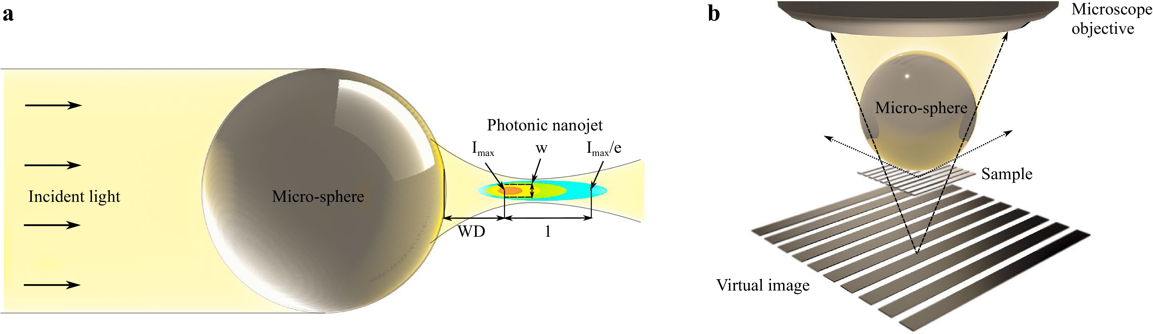
Fig. 1 Photonic nanojet and micro-sphere assisted microscopy. a Schematical illustration of a PNJ and its characteristics with the working distance WD, the peak intensity Imax, its effective lengths l, and its width w of the FWHM. The characteristics of the PNJ are influenced by several factors. These include the refractive index of the micro-sphere, the refractive index of the surrounding environment, and the sphere’s diameter, among others, as detailed in Ref. 13. b Schematical illustration of the lateral resolution enhancement in micro-sphere assisted microscopy. Ray-tracing for virtual image formation. Since the sample is within the working distance defined by the PNJ, a magnified virtual image is generated by the micro-sphere.
The PNJ phenomenon was first observed in a laser cleaning experiment in 200020, where scientists achieved a resolution of ablated silicon narrower than the diffraction limit while removing micro-/nanoparticles. Over the past decade, significant advancements have been made in leveraging PNJs with dielectric spheres as supplementary lenses in microscopy (see Fig. 1b), often referred to as microsphere-assisted microscopy5,21-23. By using low refractive-index particles (n ≈ 1.5)24 or high-index particles ($ n \, \geq $ 1.9) placed in a background medium with a lower refractive index25, exceptional resolution enhancement can be achieved in 2D through the creation of an enlarged image (virtual or real) that enhances the numerical aperture of the microscope objective used to study a sample22. This approach has been applied to various microscopes13, including fluorescent, confocal, and two-photon setups, and further extended to 3D using, for instance, interferometric objective lenses23,26.
However, certain limitations still exist in microsphere-assisted microscopy, hindering the wide exploration of the technology. One of these limitations is the small field of view, which is based on the particle’s diameter that simultaneously affects the resolution27. Another limitation is that integrating the particles within microscopes remains a challenge and, thus, hampers the flexibility in sample characterization over a specific area28. Indeed, scanning approach in microsphere-assisted microscopy has been successfully demonstrated using microspheres attached to an AFM cantilever17. However, the assembly of such a system is complex, and careful consideration is needed for selecting the proper diameter of the particles and the material of the cantilever to prevent vibrations during scanning.
One solution that holds significant potential for addressing many of these issues is the introduction of direct laser writing through multi-photon lithography (MPL) to this field. MPL has been successfully employed across multidisciplinary fields over the past decades. It has served as a powerful technique that allows for precise processing of polymers with submicron resolution and true 3D processing capabilities29-31. Therefore, the use of MPL in the field of microsphere-assisted microscopy would pave the way to engineer micro-optical elements of arbitrary geometries.
Furthermore, combining MPL with other processing techniques can facilitate the integration of micro-structures capable of generating extraordinary resolution enhancement directly into optical microscopes. This advancement could reduce the complexity associated with current solutions, making the devices more compact, stable, and easier to use.
In this paper, we demonstrate an approach that leverages femtosecond laser ablation and MPL to manufacture a 3D micro-device, which is flexible in handling and designed to enhance lateral resolution in optical microscopy via a micro-sphere. In this context, we will present an advanced strategy for MPL, specifically aimed at improving the structural quality of spherical structures fabricated from a Zr-based hybrid polymer. Additionally, we will describe the integration of these 3D micro-devices into a Mirau-type coherence scanning interferometer (MCSI) and test the performance of the device. Although MCSI is an advanced optical technique offering high axial resolution, it is traditionally diffraction-limited in the lateral direction. By incorporating the 3D micro-device into the MCSI, we successfully address this limitation and enhance its lateral resolution beyond the limits achievable with conventional lenses or microscope objectives when used with visible light in air. The results will be discussed both experimentally and theoretically. Notably, the successful testing of this micro-device within our study represents a unique achievement. To our knowledge, this is the first reported instance of remarkable resolution enhancement for MCSI achieved by MPL-processed structures.
-
Micro-sphere-assisted microscopy enhances resolution by utilizing spherical elements with diameters typically ranging from 2 µm to over 100 µm. According to paraxial geometrical optics approximations, the effective refractive index of both the sphere and the surrounding medium should be less than 2 to ensure that the focal point appears on the shadow-side surface of the sphere. Such parameters significantly influence the characteristics of the jet-like feature, the PNJ, which can be depicted in Fig. 1a. A comprehensive overview of these parameters, along with others impacting the working distance, length, or width of the PNJ, is detailed in Ref. 13.
At first glance, processing micro-spheres with MPL seems straightforward due to its nonlinear nature, which allows the fabrication of intricate 3D structures with sub-micron features. Therefore, MPL has been effectively employed to fabricate, for instance, scaffolds for tissue engineering32, free-form optical elements33,34, metamaterials35 and high-resolution photonic structures36,37.
Nonetheless, upon closer examination, processing a seemingly simple micro-sphere with MPL for its use in optical microscopy presents significant challenges, which involve balancing two essential aspects. First, achieving superior resolution enhancement necessitates a nearly perfect shape and high surface quality for the spherical element7,16. Second, the small size of a single micro-sphere fabricated by MPL complicates its integration into optical imaging systems.
In the context of this study, a practical starting point for the easy integration of such a sphere into an optical microscope involves its use in combination with a standard coverslip. These coverslips are not only easy to handle due to their size but also serve effectively as a standard substrate in MPL, including for the fabrication of standard micro-lenses33,38, as they facilitate excellent adhesion for MPL processed structures. However, in this study’s context, the coverslips require additional preparation because multiple light reflections at the interfaces of unprocessed coverslips could potentially inhibit to generate a PNJ via micro-sphere, thus impeding resolution enhancement. Specifically for the use of MCSI, integrating an unprocessed coverslip into the optical path of the interferometer would lead to alterations in both the optical path length and the focal distance. This mismatch between the focal plane and the interference plane would render high-resolution imaging via a micro-sphere unfeasible. While a micro-sphere might introduce this effect to a lesser degree, it has been experimentally demonstrated that, despite the shift in focal distance, the focal and interference planes remain sufficiently close for effective interferometric image formation26,39,40.
To counteract any issues when focusing light through the coverlip, it was preprocessed using ultrashort pulse laser radiation, facilitating the creation of micro-holes at the center of the substrates without causing cracks (see Fig. 2, left images). This modification enabled light from an optical microscope to be focused through the micro-hole onto the microstructure fabricated via MPL (see Fig. 2, right images). The microstructure consisted of a free-hanging sphere, 20 µm in diameter, positioned above the processed micro-hole and connected to the substrate by a cantilever (see Fig. 2, center bottom image). The sphere’s diameter was selected based on the refractive index of the material used for MPL, aiming to both maximize the field of view and achieve sufficient magnification for resolution enhancement. Additionally, the selection took also into account the limited choice of suitable microscope objectives for producing the micro-sphere, which will be discussed later. The height of the cantilever was set to a value of 150 µm, offering flexibility to compensate for tilt errors when integrating the device into an optical microscope.
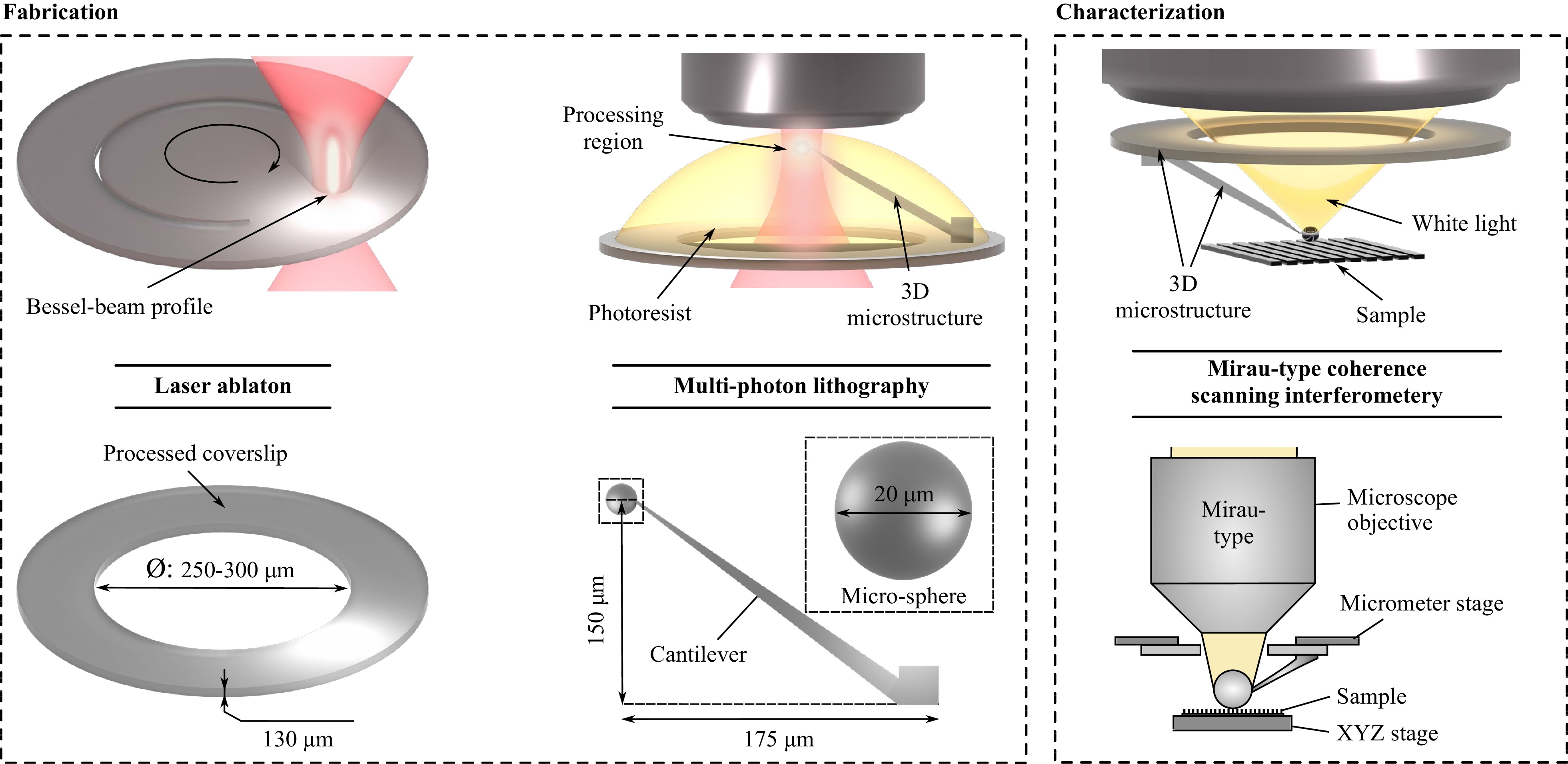
Fig. 2 Principle of fabricating and characterizing 3D micro-devices for lateral resolution enhancement in optical microscopy. The 3D micro-device comprises a coverslip with a diameter of 12 mm and a 3D microstructure. The coverslip was processed through femtosecond laser ablation to fabricate a hole in its center. The 3D micro-structure was fabricated using MPL. This micro-structure features a cantilever and a micro-sphere. The 3D micro-device facilitates the focusing of light through the modified coverslip onto the micro-sphere, enabling the characterization of its optical properties. The characterization of the micro-device was carried out using a MCSI. All processes involved are represented schematically to illustrate the principles of fabrication and testing of the 3D micro-device, with chosen scaling factors to demonstrate the specific approaches but not to represent actual size. However, important features of the micro-device are detailed with their actual sizes to provide a realistic understanding of its dimensions and structure.
Specifically, micro-holes were processed into standard coverslips with a diameter of 12 mm and a thickness of 130 µm by employing a Ti:Sa laser, which emits femtosecond laser pulses at 800 nm with a 5 kHz repetition rate. The initial Gaussian beam profile was converted into a Bessel beam profile, as detailed in Ref. 41.
MPL was realized by focusing femtosecond laser radiation at 780 nm in a photopolymer (see Fig. 2, upper center image). The optical setup further comprised a galvo scanner and a shutter, among others.
The photopolymer used for MPL is a organic and Zr-based inorganic hybrid materia 42,43 with a refractive index n of approximately 1.4844.
To assess the quality of structures fabricated by MPL, the samples were examined using scanning electron microscopy (SEM, JSM-IT700HR InTouchScopeTM, Japan). Prior to the SEM analysis, the structures were sputter-coated for 39 s at 40 mA using Au target, resulting in a 10 nm-thick film.
The functionality of the 3D micro-device in enhancing the lateral resolution was evaluated using MCSI, as schematically illustrated in the right-hand images of Fig. 2.
Further details on the optical setups and the synthesis of the photoresist used in this study can be found in the supplementary file.
-
A micro-hole was fabricated into the coverslip by moving the sample with a translating stage. The circular shape of the micro-hole was approximated using a 20-edged polygon. This polygon was subjected to laser radiation 25 times to cut through the glass. The stage velocity was maintained at 0.2 mm/s, and laser radiation had a pulse energy of 400 µJ at 5 kHz repetition rate, while the focal intensity can be calculated to I = 2000 TW/cm2 under consideration of the used optics in the optical setup (see supplementary file). It took about four minutes to process each micro-hole, which ranged in size from 250 µm to 300 µm.
Using MPL, the 3D microstructure was fabricated layer-by-layer in a bottom-up approach. A microscope objective with 20x magnification and a numerical aperture of 0.8 was used, first to create the sphere and then the cantilever. The modification of the coverslips restricted conducting MPL in a top-down approach, where laser radiation is directed through the coverslip into the photoresist. This limitation arose due to reduced transmission near the ablated area of the coverslip, likely a result of increased surface roughness, as will be demonstrated later.
The altered optical characteristics of the coverslip further implied that oil-immersive microscope objectives with high numerical apertures, while ideal for achieving the highest MPL resolution, were less suitable for bottom-up processing due to their limited working distance. Such lenses could be theoretically compatible with photoresists like OrmoComp or IP-Dip, which permit the microscope objective to be directly immersed in the photosensitive resin45,46. Nevertheless, the low viscosity of these material makes them impractical for this research. As a result, such dip-in photopolymers would not ensure a stable connection between the sphere and the cantilever.
To fabricate the 3D microstructure, the exposure paths of the laser beam were generated using the commercially available software Istos (Biomimetic, Greece). Hardware operations, including processing parameter adjustments, were controlled via Arachne (Biomimetic, Greece).
For the cantilever, the hatching and slicing parameters were set at 0.3 µm and 0.5 µm, respectively. The hatching pattern featured lines oriented in one direction, which rotated by 90° for each subsequent layer. This configuration was optimized for speed, as the primary purpose of the cantilever was to hold the sphere above the micro-hole cutted into the coverslip. The cantilever was fabricated using an average laser power of 120 mW (I = 1.44 TW/cm2), measured before the entrance pupil of the microscope objective, and a galvo speed of 30 mm/s.
For the fabrication of the micro-sphere, a grid-hatching pattern was employed as illustrated in Fig. 3. The hatching lines were uniformly spaced at 0.1 µm intervals, a parameter consistently maintained throughout the production of the micro-sphere. However, with each successive layer, the grid pattern was rotated 5° clockwise, a technique here referred to as adaptive hatching. This method allows for a more precise approximation of the circular shape for each layer of the micro-sphere47, significantly enhancing the geometric and surface quality over a static hatching method commonly used in MPL. The advantages of adaptive hatching in improving the micro-sphere’s quality in comparison to the static hatching method are further detailed in the supplementary file.
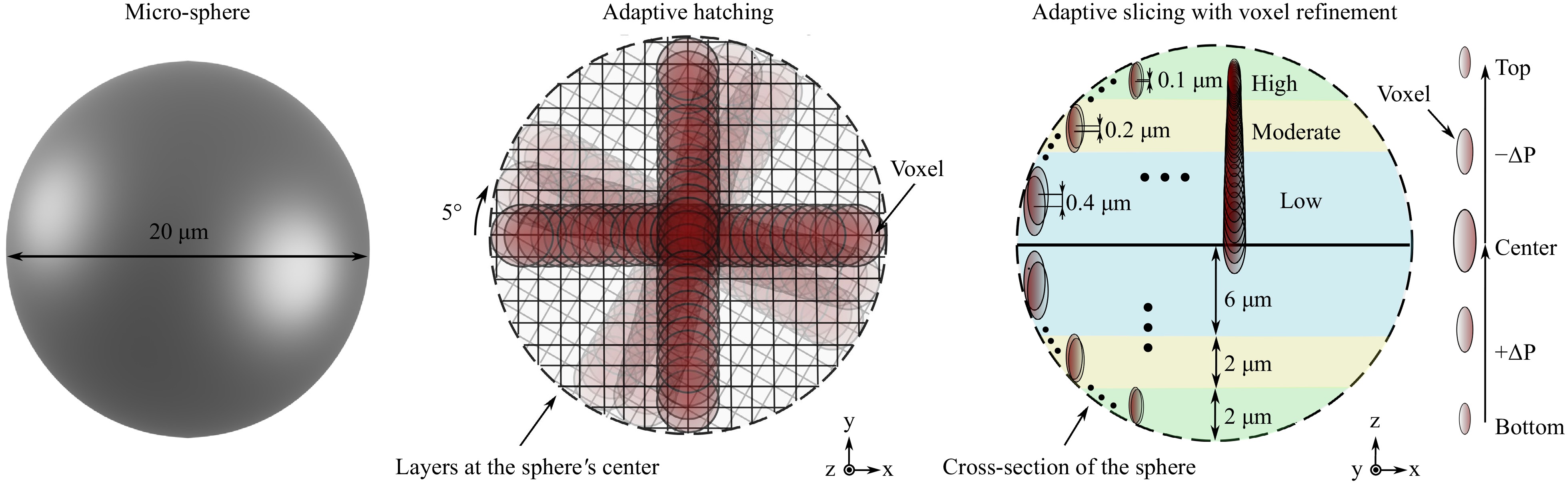
Fig. 3 Strategy for the fabrication of the micro-sphere via MPL. Principle of using adaptive hatching and slicing to enable the fabrication of micro-spheres with near-perfect geometry and low surface roughness. Adaptive hatching includes the rotation of the hatching pattern after each successive layer by 5°. The hatching lines were consistently spaced 0.1 µm apart. Adaptive slicing employs varying slicing values tailored to regions needing high (green), moderate (yellow), or low (blue) fidelity. Furthermore, it incorporates layer-specific power adjustments (∆P = 0.1 mW) to refine the voxel size, particularly important at the top and bottom surface of the sphere, where the curvature slope is steeper.
To further improve the geometrical and surface quality of the micro-sphere, a strategy named adaptive slicing was employed, which was inspired by the methodology outlined in Ref. 48. This approach involved dividing the micro-sphere into three regions, each with different slicing values optimized for areas requiring high (green), moderate (yellow), and low (blue) fidelity, as depicted in Fig. 3. This advanced fabrication strategy effectively counters the staircase effect, which increases the roughness of curved surfaces due to a mismatch between the size of the smallest building unit (voxel) used in MPL and slicing parameters48-50. Concurrently, the optimized layering used in manufacturing the micro-sphere helps mitigate the undesired polymerization volume growth, primarily along the vertical axis when identical voxels overlap consistently, a common issue in photosensitive materials due to proximity and memory effects51. Specific regions were sliced for one half of the micro-sphere with 0.1 µm for a distance of 2 µm (green), 0.2 µm for a distance of 2 µm (yellow), and 0.4 µm for a distance of 6 µm (blue), and then mirrored for the other half (see Fig. 3). The selection of these parameters and additional details on adaptive slicing in comparison to the traditionally used static slicing method are described in the supplementary file.
Additionally, the adaptive slicing strategy incorporated varying the average laser power after each layer, facilitated by an acousto-optical modulator acting as a shutter. These layer-specific power adjustments allow for tailoring the size of the voxel, as it is dependent on the square of the intensity50. Such refinement of the voxel size is particularly critical for enhancing precision in the fabrication of the micro-sphere34, especially in areas with shallow slopes near the sphere’s top and bottom surfaces (see Fig. 3 and supplementary file).
In general, the voxel size is represented in x-y direction by its diameter $ d_{v} $ and in z direction by its length $ l_{v} $. According to Ref. 52, these values can be calculated using Eq. 1 and Eq. 2, respectively, assuming that the effective order of absorption for the photoresist used in this study is 230.
$$ \begin{array}{*{20}{l}} d_{v}=2r\sqrt{2\,ln\dfrac{I}{I_{th}}} \end{array} $$ (1) $$ \begin{array}{*{20}{l}} l_{v}=2z_{r}\sqrt{\sqrt{ln\dfrac{I}{I_{th}}}-1} \end{array} $$ (2) The parameter $ I_{th} $ is the threshold intensity. The radius $ r $ and the Rayleigh lengths can be determined using the formulas $ r=0.61\lambda /NA $ and $ z_{r}=(n\pi r^{2})/\lambda $, where $ \lambda $ is the central wavelength of the laser, NA represents the numerical aperture of the microscope objective, and $ n $ the refractive index of the material. The intensity $ I $ per pulse can be estimated by
$$ I=\frac{2\,TP_{p}}{\pi r^{2}}, $$ (3) where $ T $ is the transmission of the microscope objective for central wavelength of the laser, which was in our case $T=0.8$ The peak power $ P_{p}=P_{a}/(R\tau) $ can be calculated using the average laser power $ P_{a} $, and the repetition rate $ R $, and the pulse duration $ \tau $ of the laser.
With the utilization of advanced manufacturing strategies for MPL, the fabrication of the micro-sphere initiated at its bottom surface with the average laser power set at 42.5 mW ($I=0.51$ TW/cm2). As each layer was completed, the average laser power was incrementally increased by 0.1 mW, reaching a peak of 47 mW (I = 0.56 TW/cm2) at the central layer of the sphere. Subsequently, the power was gradually decreased by the same increment until it returned to 42.5 mW (I = 0.51 TW/cm2) at the top surface of the micro-sphere. The galvo speed was consistently maintained at 8 mm/s throughout the entire fabrication process. The selection of specific average laser power values is elaborated in the supplementary file.
According to Eq. 1 and Eq. 2, along with the specifications of the laser and microscope objective used for MPL (as detailed in the supplementary file), the voxel sizes can be theoretically calculated to $d_{v}=0.4$ µm and $l_{v}=1$ µm for 42.5 mW ($I=0.51$ TW/cm2) at the top and bottom surface of the micro-sphere and $d_{v}=0.55$ µm and $l_{v}=1.4$ µm for 47 mW ($I=0.56$ TW/cm2) at its center. Prior to the fabrication of the micro-sphere, the threshold intensity of $I_{th}=0.46$ TW/cm2 was assessed at an average laser power of 38 mW and a galvo speed of 8 mm/s using the camera in the MPL setup. These theoretical results affirm that the voxels consistently overlapped throughout the fabrication of the micro-sphere.
The 3D microstructure, including the micro-sphere and the cantilever, was produced in 4 minutes, with the results presented in the SEM images in Fig. 4. Both Fig. 4a and Fig. 4b present the microstructure in top view, but at different magnifications. As evident in Fig. 4a, the 3D microstructure was successfully fabricated. It is noteworthy that the center of the micro-sphere was not perfectly aligned with the micro-hole’s center. This misalignment can be attributed to the manual setting of the starting position in the MPL process. Nonetheless, the lateral positioning was accurate enough for light to be focused through the micro-hole onto the micro-sphere. Additionally, the SEM image at a low magnification displays the increased surface roughness of the coverslip, a consequence of the laser ablation process as aforementioned.
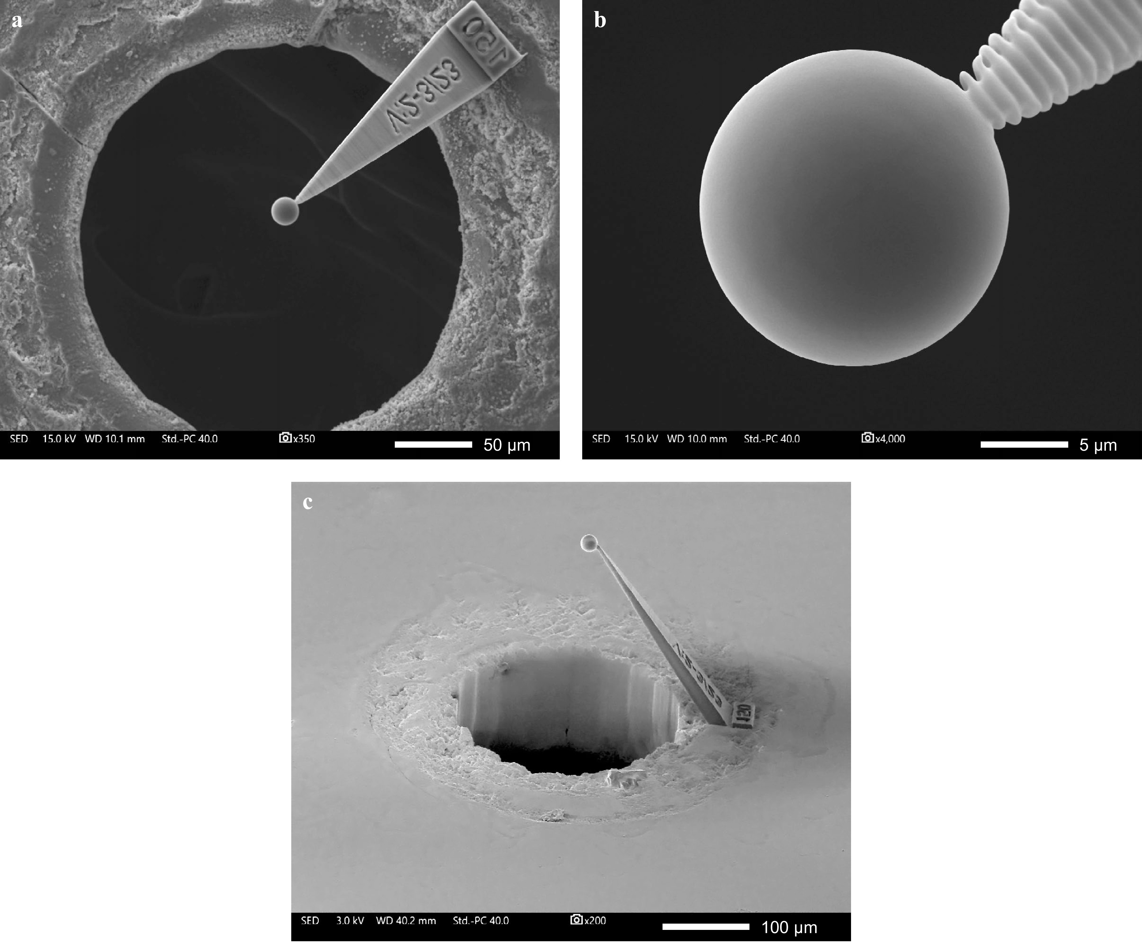
Fig. 4 SEM images of fabricated 3D micro-device. a The top-view image with low magnification shows the entire 3D micro-device, including 3D microstructure and the processed coverslips. It also illustrates the area with increased surface roughness around the cutted micro-hole. b The top-view with high magnification shows the micro-sphere and reveals its near-perfect geometry and minimal surface roughness achieved through the adaptive hatching and slicing strategy. c Tilted image (60°) of the 3D microstructure.
Fig. 4b illustrates the high quality of the 3D microstructure, as exemplified by the smooth surface and roundness of the micro-sphere. However, the processed volume of the cantilever—especially the section connecting to the sphere—appears less refined, likely due to the parameters chosen for hatching and slicing. Nevertheless, the cantilever ensures a reliable and strong connection, maintaining the micro-sphere in its designated position in the third dimension, as depicted in Fig. 4c.
Fig. 4c further emphasizes the almost-perfect spherical nature of the micro-sphere. This significant observation, coupled with the enhanced surface properties of the sphere, is a direct outcome of the processing strategy employed. Remarkably, adjusting the laser power throughout the production of the micro-sphere has emerged as a crucial factor in achieving superior geometrical quality in this context. For instance, while the use of adaptive hatching and slicing—absent layer-specific power adjustments—improved the overall quality compared to static methods, there was still slight axial elongation and other minor structural imperfections, even with the best fabrication parameters (see supplementary file). Although one might consider counteracting these slight imperfections by adjusting the 3D computer model of the micro-sphere, such as altering its shape to a more elongated ellipsoid laterally, this could lead to further complications, including a more pronounced staircase effect due to shallower slopes. Therefore, integrating adaptive hatching and slicing with layer-specific laser power adjustments for voxel refinement has proven to be an exceptionally effective method for enhancing surface characteristics and producing high-quality 3D structures.
-
After MPL, the 3D micro-device was integrated into an MCSI system to assess the micro-sphere’s ability to enhance lateral resolution in 3D optical microscopy. The dimensions of the processed coverslip allowed for easy handling of the 3D micro-device using standard laboratory tweezers (see Fig. 5a). The optical setup for the MCSI employed white light with a central wavelength of 600 nm. The microscope objective used to focus light onto the micro-sphere had a specified resolving power of 0.5 µm at the center wavelength of visible light in air, which closely approximates the theoretical Abbe diffraction limit53. To test the performance of the 3D micro-device, a calibration grating formed with Ag on chalcogenide glass was used as a sample. The grating had a period of approximately $ \Lambda $ = 0.28 µm, and its feature height h exceeded 50 nm. These specifications were previously verified through atomic force microscopy (AFM, see supplementary file).
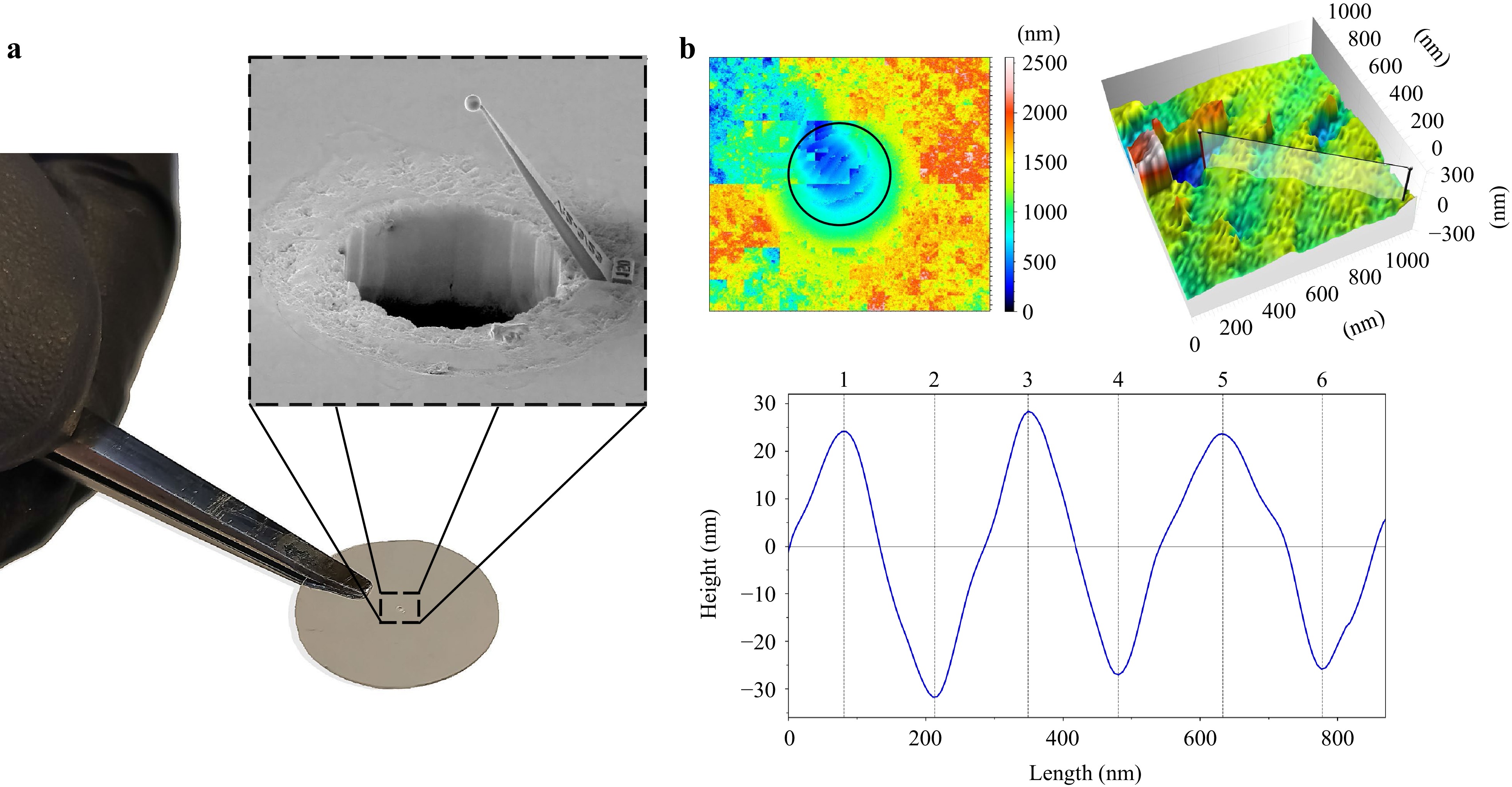
Fig. 5 Characterizing the 3D micro-device for lateral resolution enhancement using MCSI. a Demonstration of the simple handling of the 3D micro-device. b Results of MCSI using the 3D micro-device. 2D and 3D images resulting from MCSI measurements show that the almost perfect micro-sphere can enhance the resolution and as a result, enables to image feature of the Ag-grating (Λ = 0.28 µm, h > 50 nm). Such features are demonstrated in 2D as cross-sectional profile.
For MCSI analysis, the 3D micro-device was positioned between the sample and the microscope objective, as shown in Fig. 2c. A manual micrometer stage was utilized for proper assembly of the device. The Ag-grating was independently adjusted using piezo-controlled linear stages. It was carefully moved towards the 3D micro-device while the interference fringes on the top of the micro-sphere were monitored. The initial position for the measurement was determined when the interference fringes began to move in sync with the grating’s movement. Here, inital position was found when the micro-sphere was in contact with the grating. Interferogram data were then recorded by scanning over this fringe image plane, averaging each recorded image eight times, and applying a surface detection algorithm known as the 5-point algorithm54 to the recorded image stack data.
The results of the measurements are illustrated in Fig. 5b. The upper left image is a 2D image of the surface data, which were not subjected to additional post-processing, such as spherical aberration or noise filtering. Notably, much of this area lacks features that correlate with the grating. However, a distinct set of features becomes evident in the blue-colored region at the center of the 2D image, which is also marked with a black circle. For improved visualization, this region is depicted in an uncorrected 3D image at the upper right, revealing some features of the grating. A cross-sectional profile of the area marked in the 3D image is shown in Fig. 5b. The profile was smoothed using the Savitzky-Golay filter55.
The plotted cross-sectional profile indicates that the almost-perfect micro-sphere, processed by MPL, significantly enhanced lateral resolution, thus accurately enabling the imaging of the grating’s periodic nature. Therefore, its minimum resolving power must be at least equal to the grating’s period. Such fine-resolution imaging would not have been achievable using only the Mirau-type microscope objective, which has a resolving power of 0.5 µm. Furthermore, the micro-sphere processed by MPL maintained the axial resolution of the MCSI, as also evident in the profile depicted in Fig. 5b.
Using the profile, the period Λ of the grating and its height h could be calculated. Detailed values of the distances and height differences between individual features of the Ag-grating, as measured by the 3D micro-device using MCSI, are listed in Table 1. Utilizing these values, the average measurements for the grating’s period and height were calculated as Λ = 0.28 µm ± 0.014 µm and h = 54 nm ± 4 nm, respectively. These measurements closely align with the grating’s specifications (Λ = 0.28 µm, h > 50 nm), yet it is important to note that characterizing the height of such a grating using MCSI might be influenced by the complex refractive indices of the grating’s materials. Additionally, the Savitzky-Golay filter employed in the analysis might also affect the calculated height value. Despite these factors, the height measured matches well with that achieved using AFM (h = 57 nm ± 5 nm, see supplementary file).
Data 1-2 2-3 3-4 4-5 5-6 Distance [nm] 131.8 136.1 132.1 151.4 145.6 Height [nm] 55.7 60.1 54.5 51.0 50.1 Table 1. Measurements of distance and height differences between individual features of the Ag-Grating using MCSI with the 3D micro-device
In contrast, the error in determinating the grating’s period using MCSI via the micro-device using (± 0.014 µm) was larger than the error obtained using AFM (± 0.001 µm, see supplementary file). This discrepancy in precision between the two methodologies might be due to device-related factors or more likely to the imaging errors, which are evident in Fig. 5b. These imaging errors are, for instance, that the surface data displayed in the 2D image in Fig. 5b primarily consists of rectangular artifacts. These artifacts arose from the sensitivity of the employed surface detection algorithm to noisy regions in the data, leading to fluctuations in the detected surface height. This noise can be primarily attributed to the low contrast of the interference fringes. The low contrast may arise due to the micro-hole, as the ratio of the hole diameter to the cantilever height limits the light cone that illuminates the sample. Another potential source of noise is the slight misalignment between the fringe plane and the image focal plane, likely caused by the geometrical and optical properties of the micro-sphere. For example, although the processed micro-sphere generally exhibited a high quality, its maximum deviation from a perfect circle was approximately calculated to be 75 nm using Fig. 4b for the analysis. Assuming white light with a central wavelength of 600 nm, the micro-sphere, in this case, had a geometrical quality of λ/8.
Additionally, imagining errors may originate from refractive index changes within the sphere’s volume. We hypothesize that such refractive index modifications, being largest in the order of 10−2 56, result from the demonstrated manufacturing technique, which involves varying the power throughout the micro-sphere’s fabrication. Such geometrical and optical imperfections of the micro-sphere may also explain the small field-of-view (FOV), which should be ideally a quarter of the diameter of the micro-sphere according to Ref. 27. In contrast, the diffraction effects caused by the micro-hole may not have a significant impact on the imaging properties of the micro-sphere, as demonstrated in the supplementary file.
To shed more light on the results illustrated in Fig. 5b, the imaging properties of a micro-sphere with a diameter of 20 µm were simulated by Monte Carlo path tracing. Such simulation uses ray approximation of light57. Therefore, it does not consider wave effects such as diffraction, indicating that an ideal optic, in theory, would have infinite resolution. However, it accurately describes geometrical aberrations and distortions to the formed image, which is helpful for identifying other factors that limit resolution and image-forming capabilities. For simulating structural distortions, Perlin noise was employed to deform the sphere’s surface along its normal direction. Initially developed for computer graphics, Perlin noise has also proven to be helpful in modeling surface imperfections for laser scattering58. In the present case, the noise had a characteristic size of 5 µm with a peak amplitude of 1 µm. The variations in refractive index modifications (Δn) within the sphere’s volume were modeled as iso-surfaces inside the sphere, with the refractive index oscillating between 1.48 and 1.505.
The simulations for the described scenarios are presented in Fig. 6. Fig. 6a shows the intensity and shape of the focus generated by the micro-sphere and Fig. 6b illustrates the imaging properties. The checkerboard surface consisted of alternating black and white squares, each measuring 1 µm. The white squares were designed as ideal Lambertian diffuse reflectors, and the black squares acted as perfect absorbers. Both the camera and the light source possessed a numerical aperture of 0.55 (with a half-angle of 33.4°) to mimic a microscope objective under Köhler illumination. The focal point was set to be 10.5 µm beyond the checkerboard surface, resulting in a sharp image of the checkerboard pattern when viewed through the central axis of the ideal sphere.
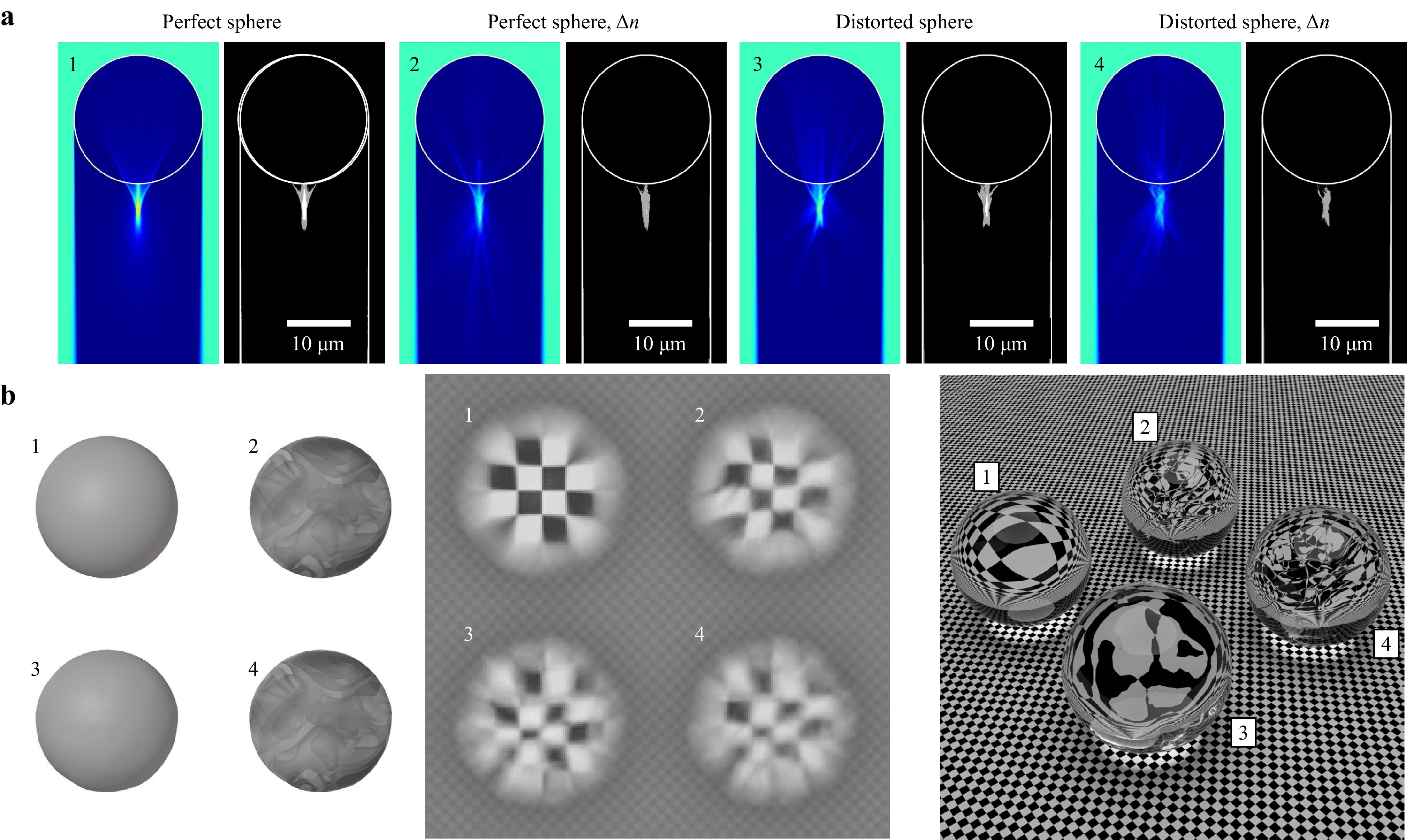
Fig. 6 Simulated imaging properties of perfect and non-perfect spheres. a The left images indicate the cross-section of light intensity. The right images illustrate the sphere dimensions and the shape of the focus. b The left images demonstrate the geometrical layout for four spheres with specific geometrical and material properties. The center images illustrate the related path-traced results. The checkerboard surface consists of alternating black and white squares with a size of 1 µm. The white squares are ideal Lambertian diffuse reflectors, and the black squares are perfect absorbers.
The simulations emphasize the key importance of both ideal geometry and consistent material properties in the micro-sphere for generating a perfectly shaped jet-like focus, the PNJ. These conditions, in turn, may facilitate enhanced resolution and superior optical characteristics. Any deviations from these ideal properties lead to significant differences in how light is scattered around the sphere and affect the form and shape of PNJ (see Fig. 6a). Precisely engineered asymmetrical deviations can ideally lead to so-called photonic hooks59. However, in the context of imaging, such deviations primarily cause optical distortions, strongly influencing the resulting imaging properties (see Fig. 6b), whereby geometrical imperfections appear to have a more pronounced impact on imaging characteristics than variations in the refractive index. These theoretical findings are well-aligned with the experimental results presented in Fig. 5b and in the supplementary file, which includes MCSI analysis using a 3D micro-device with an axially elongated micro-sphere. Interestingly, this structure also showed potential for enhancing lateral resolution. However, it failed to accurately determine the grating features.
Furthermore, simulations in Fig. 6b indicate that both geometrical imperfections and variations in the refractive index impact the effective FOV, also aligning well with the experimental results presented in Fig. 5b. Nevertheless, it is noteworthy to further emphasize that the underlying principle of superior resolution enhancement in micro-sphere-assisted microscopy may not be solely reliant on the PNJ effect, but likely involves multiple factors. For example, another key factor in resolution enhancement, highly sensitive to changes in the refractive index and a significant factor in defining the effective FOV, may be the collection of evanescent waves by the micro-sphere from the sample27,60.
-
The present research described the development of a 3D micro-device by advanced manufacturing techniques to enhance lateral resolution in optical microscopy. This 3D micro-device incorporates a modified coverslip and a fabricated 3D microstructure. The coverslip was modified by processing a micro-hole through femtosecond laser ablation. MPL was used to produce the 3D microstructures, which include a cantilever that holds a micro-sphere with a diameter of 20 µm in the third dimension above the micro-hole. Only in this configuration can light be focused through the micro-hole onto the micro-sphere, emphasizing the device’s purpose.
While the coverslip facilitated easy handling and integration of the 3D micro-device into any optical microscope, resolution enhancement in the lateral direction was realized via this micro-sphere processed from a Zr-based hybrid polymer with a refractive index of approximately 1.4844. Prior to this, we addressed various challenges in MPL processing, especially those that impacted the essential properties of the micro-sphere required for enhancing the resolution using the structure. Specifically, adaptive hatching and slicing combined with layer-specific laser power adjustments for refining the voxel were employed as advanced MPL in this study. These strategies are akin to what is known as two-photon grayscale lithography61 and were further inspired by references48,50. The novel approach yields advanced surface properties with almost perfect geometry (λ/8) (see Fig. 4), surpassing the capabilities of traditional MPL approaches50, often used in standard in-house developed MPL setups. Notably, voxel refinement through power adjustments was a key factor in effectively achieving such remarkable results (see supplementary file). However, this method also impacts refractive index modifications, an aspect that needs further exploration in future research. It is important to note that the degree of refractive modification is dependent on the exposure dose. Simultaneously, the dynamics of this modification can vary depending on the analysis technique employed, whether wave optics or ray optics approaches62.
The functionality of the 3D micro-device was explicitly and successfully tested in this work for advanced optical 3D imaging using MSCI in conjunction with white light illumination at a central wavelength of 600 nm (see Fig. 5). The 3D micro-device accurately enabled the imaging of the periodic nature of an Ag-grating and, therefore, the precise measurement of its characteristics, including both period and height (Λ = 0.28 µm, h > 50 nm). Consequently, considering the properties of the white light illumination, it was possible to surpass the resolving power of conventional microscope objectives used in air. Furthermore, these measurements showed good agreement with those conducted using AFM, and any deviations between the measurements have been thoroughly discussed.
Simulations using Monte Carlo path tracing explained potential reasons for the limitations in the functionality of 3D micro-devices (see Fig. 6). These simulations specifically highlighted the critical role of spherical geometry and consistent material properties in achieving a perfect jet-like focal feature, which is essential for extraordinary optical properties. Conversely, imperfections in these aspects dramatically impact the imaging properties, primarily through optical distortion.
In conclusion, the findings of this research provide an initial proof of concept for the successful implementation and application of the proposed 3D micro-device to enhance remarkably lateral resolution in optical microscopy. Fabricated in just 8 minutes, the device strongly hints at its potential adaptability to advanced optical imaging methods, not only in 2D but also 3D. Future improvements of 3D micro-devices might consider post-processing methods using UV light or temperature to uniform the refractive index63. Alternatively, a long working distance microscope objective with a higher numerical aperture could be employed to achieve a geometrical quality better than λ/8.
In particular, the introduction of MPL in this research field marks a significant advancement since the physical mechanism of the resolution enhancement via micro-spheres has neither been fully derived nor understood. As discussed by many authors and this study, a superior lateral resolution enhancement might not only result from the jet-like focus, the PNJ, but from the superposition of multiple phenomena, including evanescent wave collection27,60 and whispering gallery mode excitation64.
Since MPL enables the processing of microstructures with nanometer precision and full flexibility in 3D, it holds significant promise for advancing research in understanding the mechanisms behind this extraordinary effect. Additionally, the unique capabilities of MPL enable the exploration of innovative structures that may improve certain aspects of lateral resolution enhancement. For example, cylindrical structures, like optical or polymer fibers, have been shown to enhance the field of view65,66. MPL also offers the potential to fabricate resolution-enhancing optics and standard (diffraction) optics and integrate them into one 3D micro-device. Such a system could allow for modifying the incident beam profile, for example, from Gaussian to Bessel, thereby increasing the working distance or lengths of the PNJ.
Clearly, from a future perspective, there are numerous options for using MPL in this field with a high potential to cost-effectively develop custom-designed structures enabling resolution enhancement for any optical microscope technique worldwide. Thus, the creation of a 3D micro-device, and its demonstrated functionality to enhance lateral resolution in optical microscopy, particularly in a 3D imaging approach, can be seen as an initial platform to shift research from micro-sphere assisted microscopy towards micro-structure assisted microscopy and, in this context, optimize the beautiful invention that began with a combination of at least two lenses, placed consecutively, to achieve higher magnification.
-
The authors declare that there is no conflict of interest regarding the publication of this manuscript.
-
This project was supported by the Marie Skłodowska-Curie Actions, under grant agreement No. 101059253, as part of the European Union’s Horizon Europe research and innovation programme. It also received support from a Feodor Lynen Postdoctoral Fellowship awarded by the Alexander von Humboldt Foundation. Additional funding was provided by Laserlab-Europe (Proposal IDs: ULF-FORTH_002794 and ULF-FORTH_025264). We further gratefully acknowledge funding by the German Federal Ministry for Economic Affairs and Climate Action under grant 16KN053050. The authors would also like to thank Mrs. Aleka Manousaki for SEM technical support.

 DownLoad: