


-
In life science, medical diagnosis, and many other fields, such as observing neurological activity in the cerebral cortex of animals, microbial activity observation and sample screening, a microscope with at least a millimetre-level field-of-view (FOV), nearly millimetre-level depth of field (DOF), and micrometre-level resolution is required1-4. However, the FOV, DOF, and resolution are constrained by each other in a microscope5,6, making it difficult to simultaneously satisfy these performance parameters. In traditional microscopes, this problem is solved by changing the objective and moving the stage to switch magnification as well as extend the working distance (WD). However, these processes usually require a few seconds, which severely limits the application of traditional microscopes, especially in three-dimensional (3D) dynamic imaging and large-amount or large-size sample screening. For example, the deformation of cells7, movement of microorganisms8, and the calcium response of the cerebral cortex9 usually occur within a few tens of milliseconds. As another example, consider that a sample usually has different scales and different depths; consequently, the observation magnification and focal plane need to be repeatedly adjusted during sample scanning. Therefore, achieving fast zooming, a wide WD range and a large FOV in one microscope is desirable.
In recent years, researchers have proposed laser scanning confocal technology10-12, Fourier ptychographic imaging technology13-15, deep learning16-18, and some other innovative methods19,20 to enhance both the FOV and resolution of imaging systems. Nevertheless, these technologies still suffer from compromises in real-time properties or generalisation to some extent, and the WD range remains greatly limited. Recently, liquid lenses21-25 have provided a solution for fast zooming and extending WD in imaging systems. In liquid lenses, focal length changes are achieved by adjusting the interface curvature instead of mechanically moving the lenses. However, it is difficult for liquid-lens-based microscopes to achieve a millimetre-level FOV26-28. A liquid lens with a limited aperture can easily become a vignetted or field stop when the FOV is enlarged. Moreover, selecting the proper beam portion for imaging is difficult by setting the lens size and stop aperture during the optimisation process, thereby increasing the difficulty of correcting aberrations related to the FOV. Some novel optical structures have been proposed to segment the FOV for aberration correction29-32, especially multiscale imaging technology33-35, which offers a great optimisation freedom degree to correct aberrations of systems with large FOVs36,37. However, currently reported multiscale imaging systems are generally long, bulky, and difficult to assemble38, resulting in a fixed focal length and poor adaptability. Traditional mechanical zooming methods based on lens group movement39,40 are difficult to apply in multiscale imaging systems, and it is almost impossible to achieve a zooming function and WD adjustment with a fast response time41-43. In summary, achieving a combination of fast zooming, wide WD range and large FOV on one microscope remains challenging.
In this study, inspired by multiscale and liquid lenses technologies, we developed an adaptive multiscale (AMS) microscope with fast zooming, an extended WD and a large FOV, as shown in Fig. 1. The key aspects of this work include the following: (1) An AMS imaging mechanism is proposed that combines the benefits of liquid lenses and multiscale imaging techniques to achieve fast zooming, extended WD and large FOV. (2) Three unique design principles are proposed for the AMS optical structure which ensures that the AMS mechanism can be transformed into practical microscopes; (3) A nonuniform-distortion-correction algorithm and a composite patching algorithm are designed to correct the distortion of imaging systems with irregular lenses and reduce the impact of vignetting, which improves the image quality. Benefiting from the AMS mechanism, the proposed microscope offers a continuous tunable magnification range from 9× to 18× with corresponding FOV diameters from 2.31 to 0.98 mm and corresponding resolutions from 161 to 287 line-pairs/mm (lp/mm), an extended WD range of 0.8 mm and a zoom response time of 38 ms. The AMS microscope was well integrated and experiments verified the feasibility of the AMS mechanism. We demonstrated the advantages of the AMS microscope for applications in pathological sample scanning, thick-sample imaging, microfluidic process monitoring, and the observation of living microorganisms. The proposed AMS microscope is the first step towards zoom multiscale imaging technology and is expected to be applied in life sciences, medical diagnosis, and industrial detection.
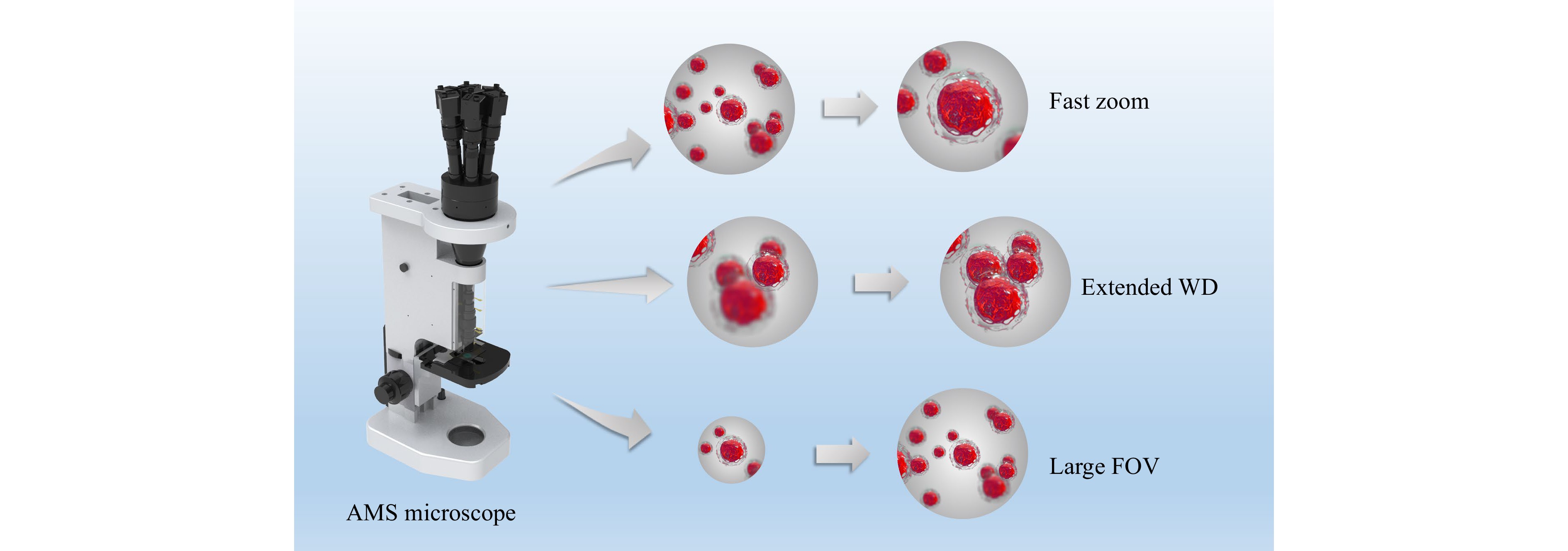
Fig. 1 Concept of the AMS microscope with a combination of fast zooming, extended WD, and large FOV.
-
The main optical parts of the AMS microscope consist of a zoom objective, compound eye lens, sub-lens array, and image sensor array, as shown in Fig. 2a. The zoom objective consists of several solid lenses and four liquid lenses. The upper surface of the compound eye lens consists of seven sub-spherical-surfaces with the same radius of curvature, and the lower surface is completely spherical. The sub-lens array consists of seven sub-lenses, each connected to an image sensor.
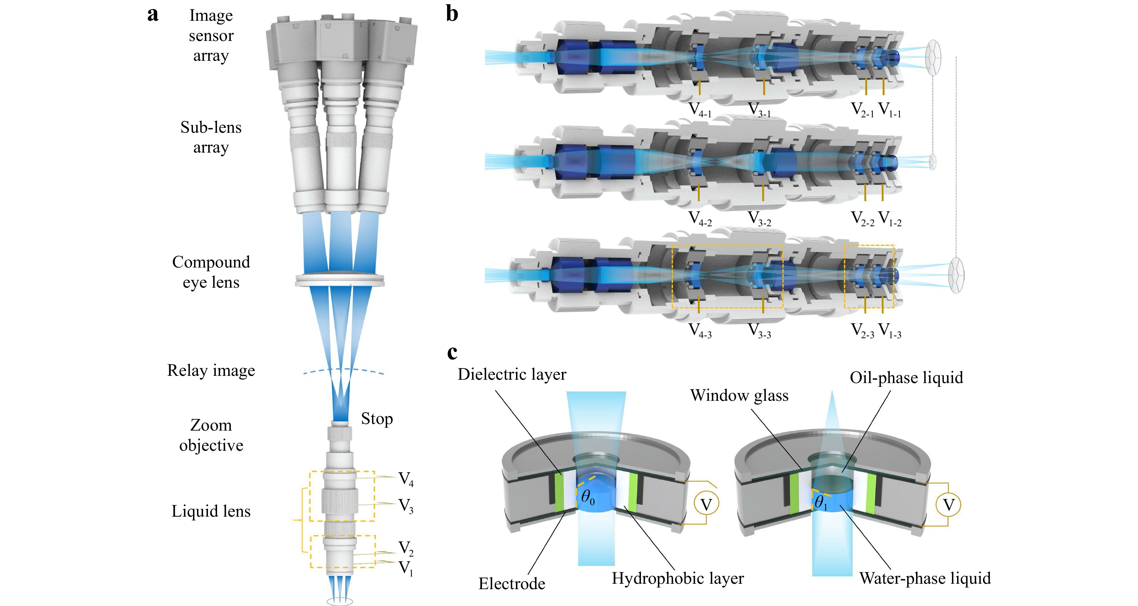
Fig. 2 Structure and principle of the AMS microscope. a Structure of the AMS microscope. b Mechanism of the zoom objective to achieve the zooming function and WD extension. c Liquid lens in a concave lens state without applied voltage and in a convex lens state with an applied voltage.
After the voltages on the liquid lenses were initialised, the target to be observed was magnified using the zoom objective to form a curved relay image. The relay image beam was then divided into seven sub-FOV beams after passing through the compound eye lens. Finally, the sub-FOV beams entered the corresponding sub-lenses and focused on the image sensors to form microscopic images. By adjusting the driving voltages of the liquid lenses in the zoom objective, the overall focal length of the microscope was changed, thereby obtaining the specified magnification and WD, as shown in Fig. 2b. Benefiting from the multiscale structure, the aberration of the zoom objective, especially the field curvature, is well corrected; thus, the microscope obtains large FOV and high resolution. There is no mechanical movement of any components during the zoom process, which is the foundation for stable and fast zooming. The above section describes the AMS imaging mechanism.
There are three key design principles for the AMS microscope. First, the stop of the zoom objective is located on the last surface. Second, the spherical centre of the compound eye lens and sub-lens array coincide with the stop. These two settings can reduce pupil aberration and the differences between the resolutions of different FOVs. Third, in the zoom range, we need to ensure a match of the focal surface between the zoom objective and the acquisition lens, including the compound eye lens and the sub-lens array. In other words, during the zooming process, the curved relay image and the lower surface of the compound eye lens should remain as concentric as possible, and the geometric relationship can be derived as follows:
$$ {\left( {{r_0} - L} \right)^2} = {\beta ^2}{h^2} + {\left( {{r_0} - L - s} \right)^2} $$ (1) where s is the Pizwald field curve of the zoom objective, β is the magnification of the zoom objective, h is the corresponding centre beam height of the edge channel on the object surface, L is the distance between the centre of the relay image and the compound eye lens, and r0 is the radius of curvature of the lower surface of the compound eye lens. When setting up multiple configurations to simulate the different focal length states of the microscope during the optical design, each configuration is expected to satisfy the above conditions as much as possible. Therefore, the corresponding objective function for optimisation can be expressed as
$$ \sum\limits_{i = 1}^k {\left( {\frac{{{s_i^2} + {\beta _i^2}{h_i^2}}}{{2{s_i}}} + L - {r_0}} \right)} \to 0 $$ (2) where k represents the number of working configurations of the microscope for different focal lengths. In Eq. 2, s, β, and h are all functions of the optical power of the liquid lenses. Each liquid lens is composed of two immiscible transparent liquids with different refractive indices and the same density, a dielectric layer, a hydrophobic layer, a ring electrode, two window glasses, and a cavity. As shown in Fig. 2c, when the driving voltage of the liquid lens changes, the curvature of the liquid–liquid interface varies owing to changes in wettability, which satisfies the Young–Lippmann equation44
$$ \cos {\theta _1} = \cos {\theta _0} + \frac{{\varepsilon {V^2}}}{{2d{\gamma _{12}}}} $$ (3) where θ1 is the working contact angle, θ0 is the initial contact angle, ε is the dielectric constant of the dielectric layer, V is the driving voltage, d is the thickness of the dielectric layer, and γ12 is the surface tension between the oil-phase liquid and the water-phase liquid.
The optical power Φ of the liquid lens can be expressed as45
$$ \varPhi = \frac{{(2{\gamma _{12}}d\cos {\theta _0} + \varepsilon {V^2})({n_2} - {n_1})}}{{{\gamma _{12}}dD}} $$ (4) where D is the aperture of the liquid lens and n1 and n2 are the refractive indices of the water- and oil-phase liquids, respectively.
-
After establishing the initial structure, we used the optical design software OpticStudio® for simulation and optimisation. The zoom objective consisted of seven spherical solid lenses and four liquid lenses. Each sub-lens consisted of three spherical solid lenses aligned with the corresponding sub-surface of the compound eye lens. The radius of curvature of the lower surface of the compound eye lens was 160 mm, and the angle between the optical axes of the edge and centre sub-lenses was 6.6°. The wavelengths used for simulation and optimisation were 486, 587, and 656 nm, respectively. The actual ray tracing and optimisation were performed from the image side to the object side to guarantee a fast convergence rate.
The simulated optical paths of the microscope at 9×, 13× and 18× magnifications are shown in Supplementary Fig. S1a–c. The local enlarged images of the simulated optical paths (Supplementary Fig. S1d–f) show that changes in the FOV and numerical aperture can be easily observed at different magnifications. The simulation results show that, when the magnification varies from 9× to 18×, the total FOV diameter changes from 2.4 to 1.04 mm, and the resolution (when the modulus of the optical transfer function is 0.1) reaches from 170 lp/mm (corresponding to a line width of 2.94 μm) to 360 lp/mm (corresponding to a line width of 1.39 μm), as shown in Supplementary Fig. S2. It should be noted that beam splitting occurs at the FOV intersection of centre and edge channels, which may lead to the appearance of a vignetted boundary and a reduction in resolution. The resolution of these boundary areas can be reduced to approximately at most half that of the centre area; however, these boundary areas are limited, as shown in Supplementary Fig. S3. WD extension was achieved by adjusting the liquid lenses. Supplementary Fig. S4 shows the simulation of the resolution with the variation in WD for different magnifications, where it can be observed that, even at the lowest magnification, the DOF cannot reach 0.8 mm. However, based on the tunable characteristics of liquid lenses, when the AMS microscope is set to a certain initial magnification, focusing can be achieved within a wider WD range by adjusting only the focal length of the liquid lenses. This will be demonstrated through experiments later.
After fabrication and assembly of the microscope, as shown in Fig. 3a and Supplementary Fig. S5, a 10 × 10 chequerboard image with a total side length of 2 mm and resolution test target USAF 1951 were used to evaluate the actual imaging performance of the microscope. The experimental results show that the microscope can achieve a zoom ratio of 2, with a FOV diameter from 2.31 to 0.98 mm and resolutions from 161 lp/mm (Element-3, Group-7 of the resolution target, which corresponds to a line width of 3.10 μm) to 287 lp/mm (Element-2, Group-8 of the resolution target, which corresponds to a line width of 1.74 μm), as shown in Fig. 3b–d. Supplementary Fig. S6 shows the contrast between the different elements at different magnifications for both the horizontal and vertical lines of the resolution target. The driving voltage and imaging performance data at different magnifications are shown in Fig. 3e, f, respectively. The directly captured imaging area of the edge channel on the image sensor changes with variations in magnification, which is caused by changes in the position and size of the field stop. At low magnification, the liquid lens in the zoom objective is the field stop, whereas at high magnification, the compound eye lens is the field stop. However, part of the outer edge regions of the images that suffer significant vignetting is beyond our designed FOV range; therefore, it was discarded during stitching and can be regarded as a fixed digital field stop set on the image sensor. As predicted in the simulation, there is a vignetted boundary at the FOV intersection of the centre and edge channels, which causes a decrease in contrast to some extent. However, continuous FOV information was entirely captured. We placed the resolution test target at the boundary of the centre channel as well as the FOV intersection between the edge channels (Supplementary Fig. S7). It can be observed that the same element can be captured by the centre and edge channels as well as the edge channel and adjacent edge channel simultaneously, which proves the continuity of the FOV. After setting the initial magnifications to 9×, 13×, and 18× at a WD of 1.13 mm, the WD was extended by controlling the liquid lenses. We chose to analyse the experimental results of WD extension at WDs of 0.65, 0.85, 1.05, 1.25, and 1.45 mm as representative results, as shown in Fig. 4 and Supplementary Figs. S8–S10. At an initial magnification of 9×, the magnification and resolution with different WDs could be maintained at a level similar to that of the initial state. At an initial magnification of 13×, the magnification remained almost unchanged and the resolution was maintained at a level similar to that of the initial state. At an initial magnification of 18×, owing to the shallow DOF and the fact that some liquid lenses have reached the limit of their optical power range, it is difficult to correct aberrations while controlling the magnification; consequently, obvious imaging aberrations, such as chromatic aberration, occur in the edge channel, which causes a decrease in resolution.
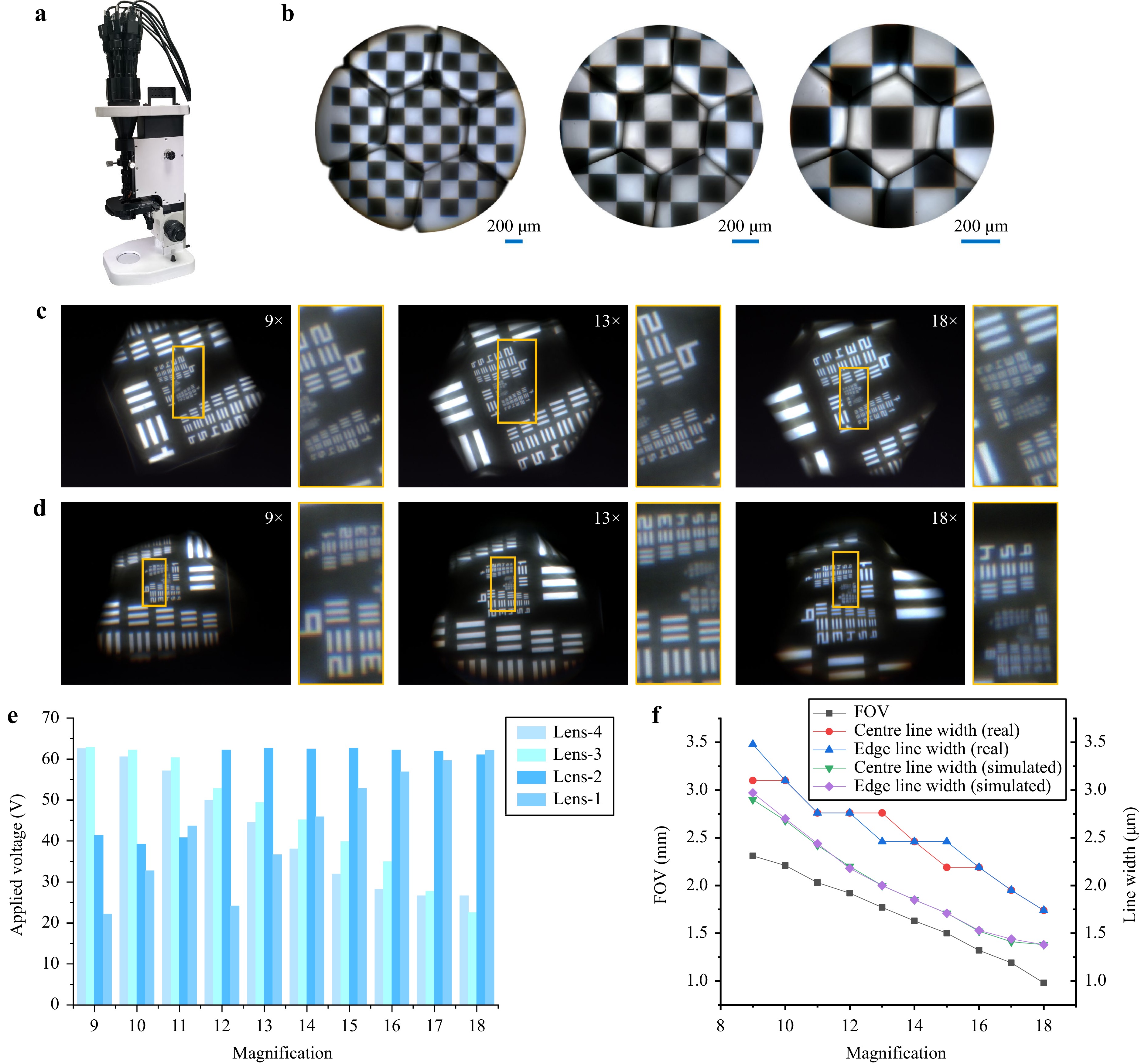
Fig. 3 Fabrication and imaging performance test results for the AMS microscope. a Real image of the AMS microscope. b FOV test results at magnifications of 9×, 13×, and 18×. c Resolution test results of the centre channel at magnifications of 9×, 13×, and 18×. d Resolution test results of the edge channel at magnifications of 9×, 13×, and 18×. e Driving voltage data for liquid lenses at different magnifications. f FOV data and resolution test results at different magnifications.
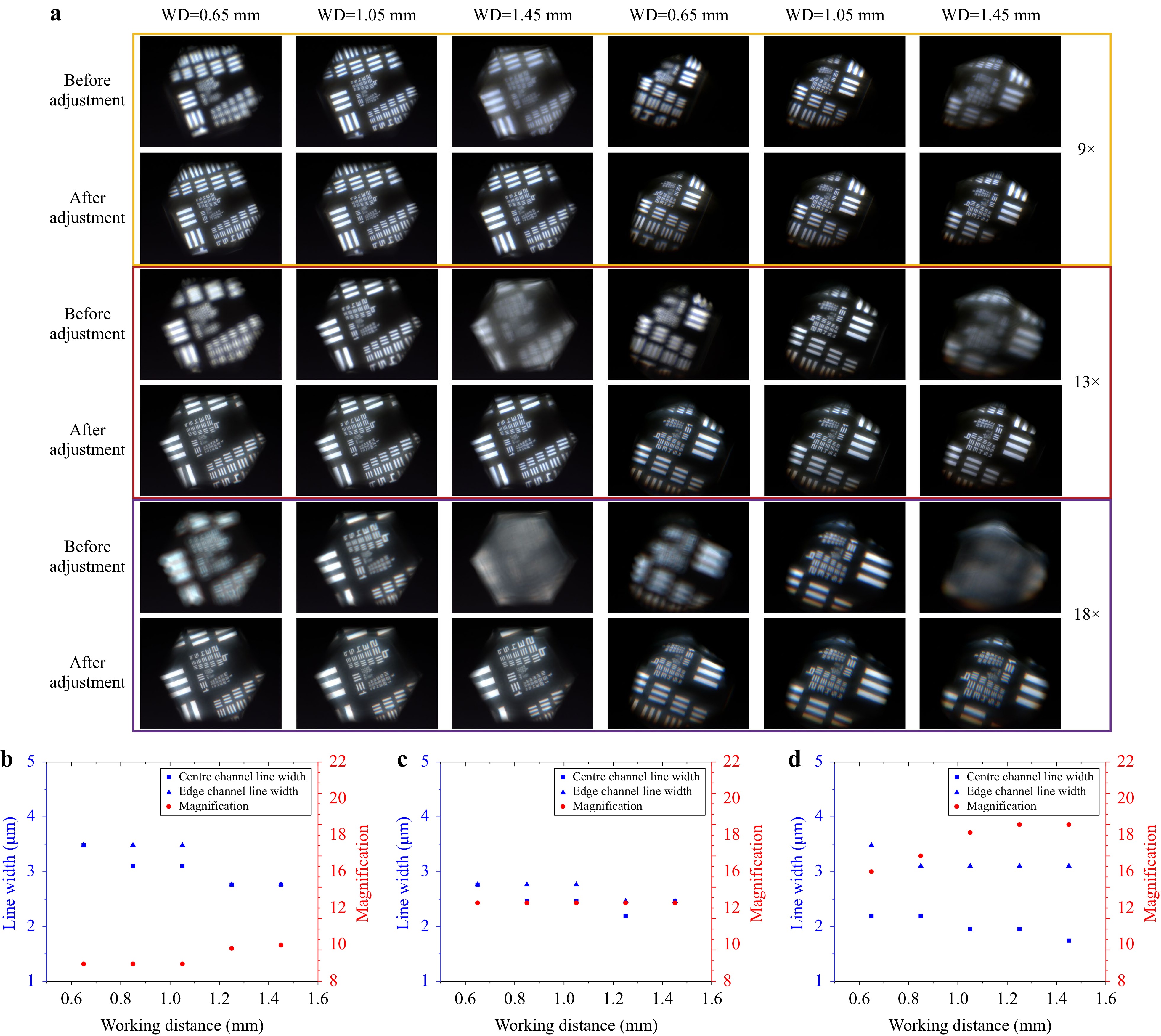
Fig. 4 Test results of the WD extended function of the AMS microscope. a Resolution test results with different WDs and different initial magnifications. b–d Resolution and measured magnification data with different WDs and different initial magnifications.
-
Benefiting from the AMS mechanism, the proposed microscope has the advantages of fast zooming, extended WD, and large FOV compared to conventional optical microscopes. It can support an efficient search, high-throughput observation, and fast capture of target details. Consequently, the proposed microscope can be applied in many scenarios. We demonstrated the application of the AMS microscope to pathological sample scanning, thick-sample imaging, microfluidic process monitoring, and living microorganism observation. Moreover, we designed a nonuniform-distortion-correction algorithm to correct the distortion of such imaging systems with irregular lenses; this is difficult to achieve using traditional algorithms that can only correct tangential and radial distortions. In addition, we proposed a composite patching algorithm to reduce the impact of vignetting on image integrity. The execution of these two algorithms may be essential in certain scenarios, such as pathological diagnosis.
-
For pathological diagnosis, the number of pathological slides that must be screened daily is usually large. Traditional observation methods require using a microscope at low magnification to locate suspicious lesion areas and then switching to a high-magnification objective or moving the internal lens group and refocusing for detailed observation. The switching time is usually a few seconds, which severely limits testing efficiency. This problem can be solved effectively using the AMS microscope, as shown in Fig. 5a. The zooming function of the AMS microscope is accomplished entirely through the liquid lenses; therefore, the magnification switching time is far shorter than that of mechanical zooming. The zoom response time of the AMS microscope is entirely determined by the liquid lenses, whose rise response time (from 0 to maximum voltage) is approximately 20 ms and fall response time (from maximum voltage to 0) is approximately 38 ms, as shown in Fig. 5b. Therefore, the maximum magnification switching time of the AMS microscope is 38 ms.
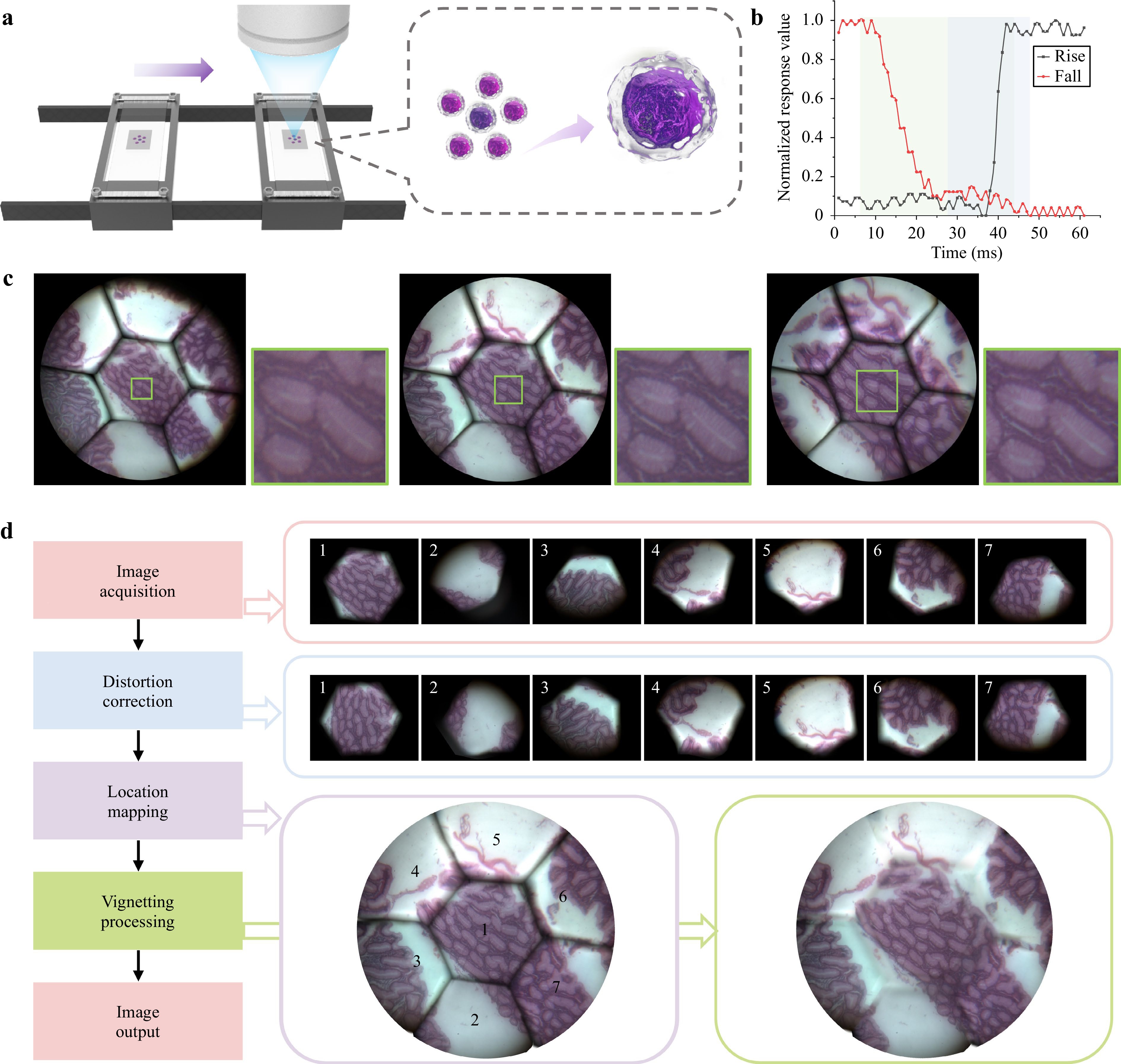
Fig. 5 Pathological sample imaging using the AMS microscope. a Schematic of the application of fast continuous zooming in pathological sample scanning. b Rise and fall response times of the liquid lens. c Pathological sample images captured by the AMS microscope with magnifications of 9×, 13×, and 18×. d Image acquisition and processing scheme.
To demonstrate the effectiveness of the AMS microscope, pathological atrophic gastritis samples were captured at different magnifications (Fig. 5c and Supplementary Video 1). As the magnification increased, the details of the cells became clearer, which contributed to an efficient search and more detailed observations. We also designed an image-processing scheme and applied two algorithms for more accurate image restoration, as shown in Fig. 5d. Taking an image with a magnification of 13× as an example, we first implemented a nonuniform-distortion-correction algorithm (Supplementary Fig. S11). The nonuniform-distortion-correction algorithm not only resists the problem of nonuniform local distortion but also eliminates the magnification consistency errors of different FOVs caused by possible assembly errors. After distortion correction and location mapping, the misalignment of the stitched images was reduced obviously. We then adopted a composite patching algorithm to process the vignetting (Supplementary Fig. S12). We patched the vignetted area at the boundary of the centre FOV by transplanting pixels from images with other magnifications and patched the vignetted areas among the edge sub-FOVs using the PatchMatch algorithm46. It can be seen that the vignetted effect has been reduced to a large extent. A detailed introduction to the algorithm execution process is provided in the Materials and methods section.
-
In conventional microscopes, focusing is tedious and time-consuming. Additionally, the shallow DOF of an ordinary microscope limits the permitted observable thickness of the sample47. Rapid focusing and WD extension are important for microscopy. In this study, we demonstrated the advantages of the AMS microscope by capturing thick samples. A 3D-printed piece with the patterns “B,” “U,” “A,” “A,” and “aircraft” was manufactured with a layer height interval of 0.2 mm, as shown in Fig. 6a. A commercial industrial microscope (Jingchang Technology Co., Ltd., JC-2001G, with a 4.5× objective lens) failed to capture clear images of the five patterns at once, as shown in Fig. 6b, and adjusting the focus plane mechanically would take several seconds. Although the proposed microscope also cannot capture all clear images of five patterns at once, as a result of the fast response time of the AMS microscope, clear images of the five patterns were successfully captured within 0.2 s, as shown in Fig. 6d, e. Moreover, within the WD range of 0.8 mm, the magnification of the proposed microscope can remain almost unchanged through cooperative adjustment of the liquid lenses, enabling the microscope to achieve an effect similar to that of a telecentric lens. In fact, the obtained images can also be used for 3D display48, as depth information can be calculated based on the voltages of the liquid lenses.
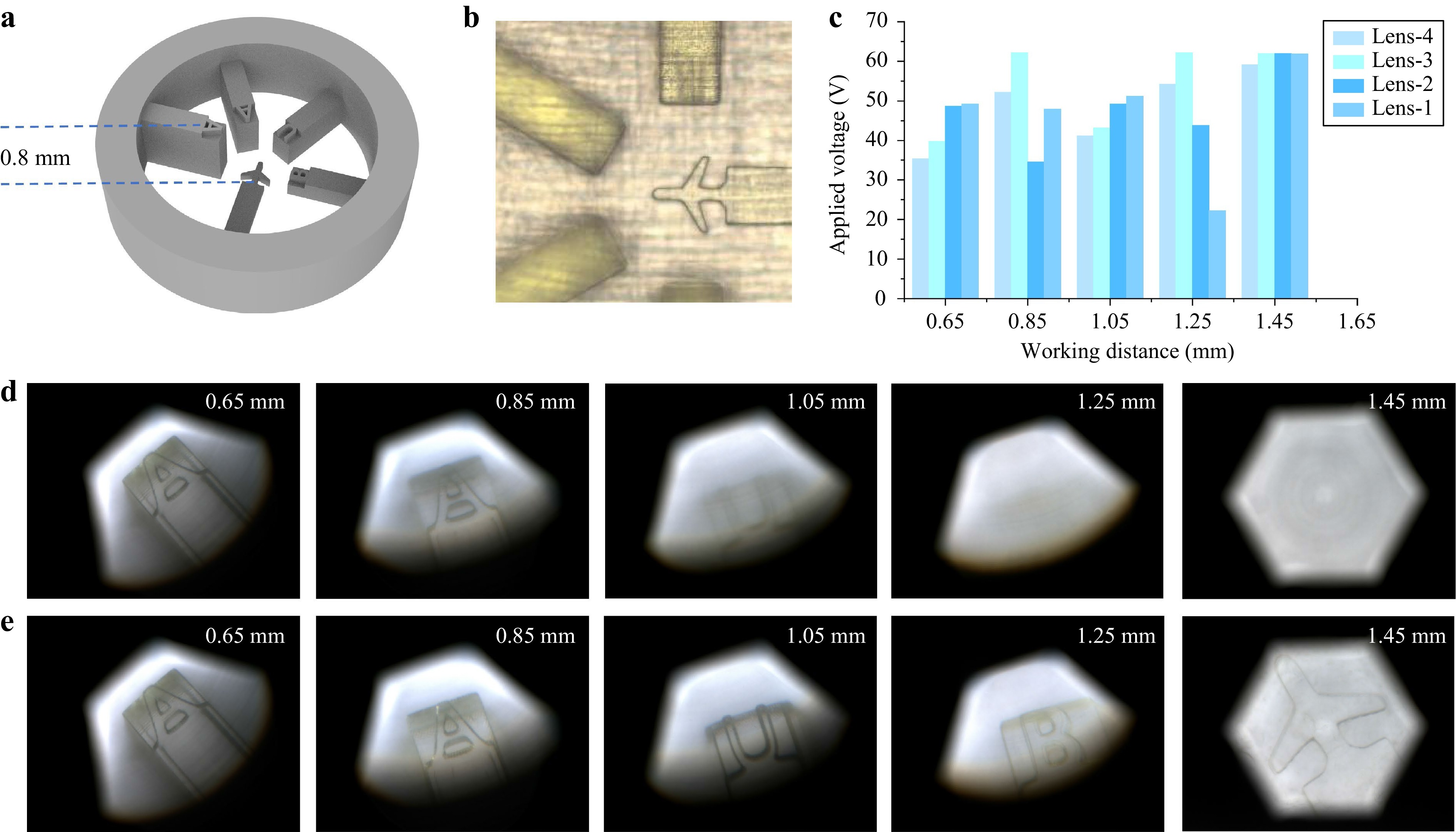
Fig. 6 Thick-sample imaging using the AMS microscope. a 3D printing sample model used for testing the WD extension performance of the proposed microscope. b Sample images captured by a commercial industrial microscope. c Driving voltage data for the liquid lenses when the AMS microscope works with different WDs. d Images captured in the initial state without changing driving voltages. e Images captured through WD extension of the AMS microscope.
-
A large FOV is an important indicator for microscopic observations. A small FOV may lead to the loss of critical information, particularly in dynamic scenes. In this study, we selected microfluidic process monitoring as an application to demonstrate the advantage of the AMS microscope on FOV. We manufactured a microfluidic chip for particle separation using 3D printing (Fig. 7a, Supplementary Fig. S13b). According to the laminar flow principle, when a solution with particles and a pure solution are injected from the two channel ports of the microfluidic chip, particles of different sizes will flow in different directions. As shown in Supplementary Fig. S13a, the theoretical particle effluent position y in the broadened segment can be expressed as49
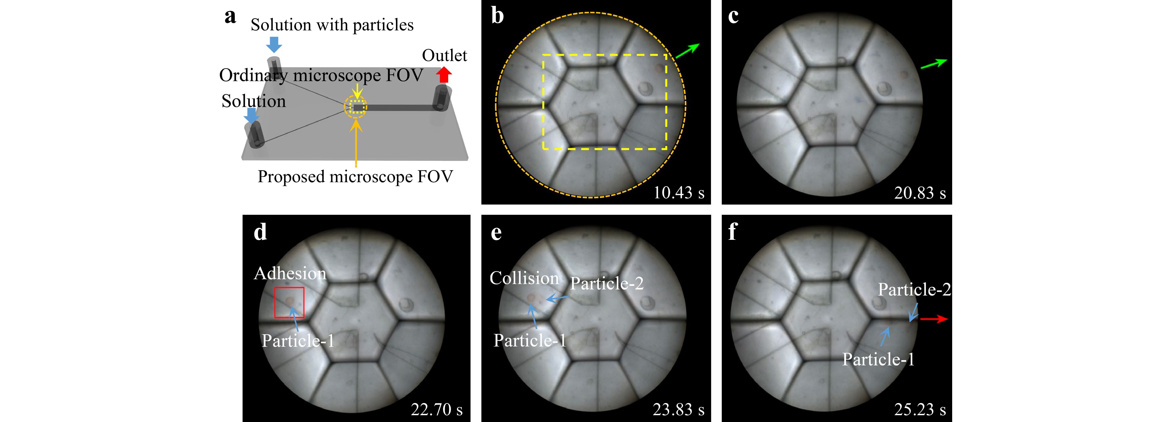
Fig. 7 Microfluidic process monitoring using the AMS microscope. a Microfluidic chip for separation of particles. b, c Flow directions of red particles under normal conditions. d–f Record of the occurring process of abnormal flow direction caused by particle adhesion in the flow channel and particles crashing.
$$ y = \frac{{(2{W_{\text{P}}} - {D_{\text{P}}}){W_{\text{B}}}}}{{2{W_{\text{P}}}}} $$ (5) where WP and WB are the widths of the pinched and broadened segments, respectively, and DP is the particle diameter. During particle separation, by controlling the flow rate ratio of the two channels, if the width occupied by the solution with particles in the pinched section is less than the particle diameter, the flow direction of the particles can be better controlled, improving the separation effect. We injected the solution with particles and the pure solution at a flow rate ratio of 1:4 and recorded the process (Supplementary Video 2, Fig. 7b–f). The particles comprised red particles with an average size of 70 μm and green particles with an average particle size of 30 μm. Because the width of the solution with particles in the pinched segment was greater than the diameter of the green particles, the flow directions of the green particles were somewhat dispersed, while the flow directions of the red particles were relatively regular. However, at 25.23 s, we observed an abnormal red particle flow direction that exceeded the error range (Fig. 7f). According to Eq. 5, this flow direction theoretically occurs only when the particle size is equal to the width of the pinched segment. This can be explained as follows: As shown in Fig. 7d, e, a red particle adhered to the wall of the microfluidic channel at 22.70 s and another particle collided with it at 23.83 s. As a result, the two red particles obtained momentum perpendicular to the laminar direction. A conventional single-aperture microscope (Phoenix Optics. PH100-3A41L-EP) with the same magnification and image sensor was used for photography. Given that the FOV (yellow area in Fig. 7b, Supplementary Fig. S14) is only ~40% of that of our AMS microscope, the above process information could not be captured.
-
To demonstrate the comprehensive functional advantages of the large FOV and fast response speed in dynamic scenes, we used the proposed microscope to capture videos of living microorganisms. Owing to the rapid movement of living microorganisms, they may easily escape the FOV of a conventional microscope and do not leave sufficient focal length adjustment time for operators. Using the AMS microscope, we fully recorded the motion trajectory of a paramecium within 150 s at a frame rate of 30 frames/s (Fig. 8a, b, Supplementary Video 3). A frame-difference algorithm50 was used for automatic recognition of the paramecium position, with the criterion for determining the position being
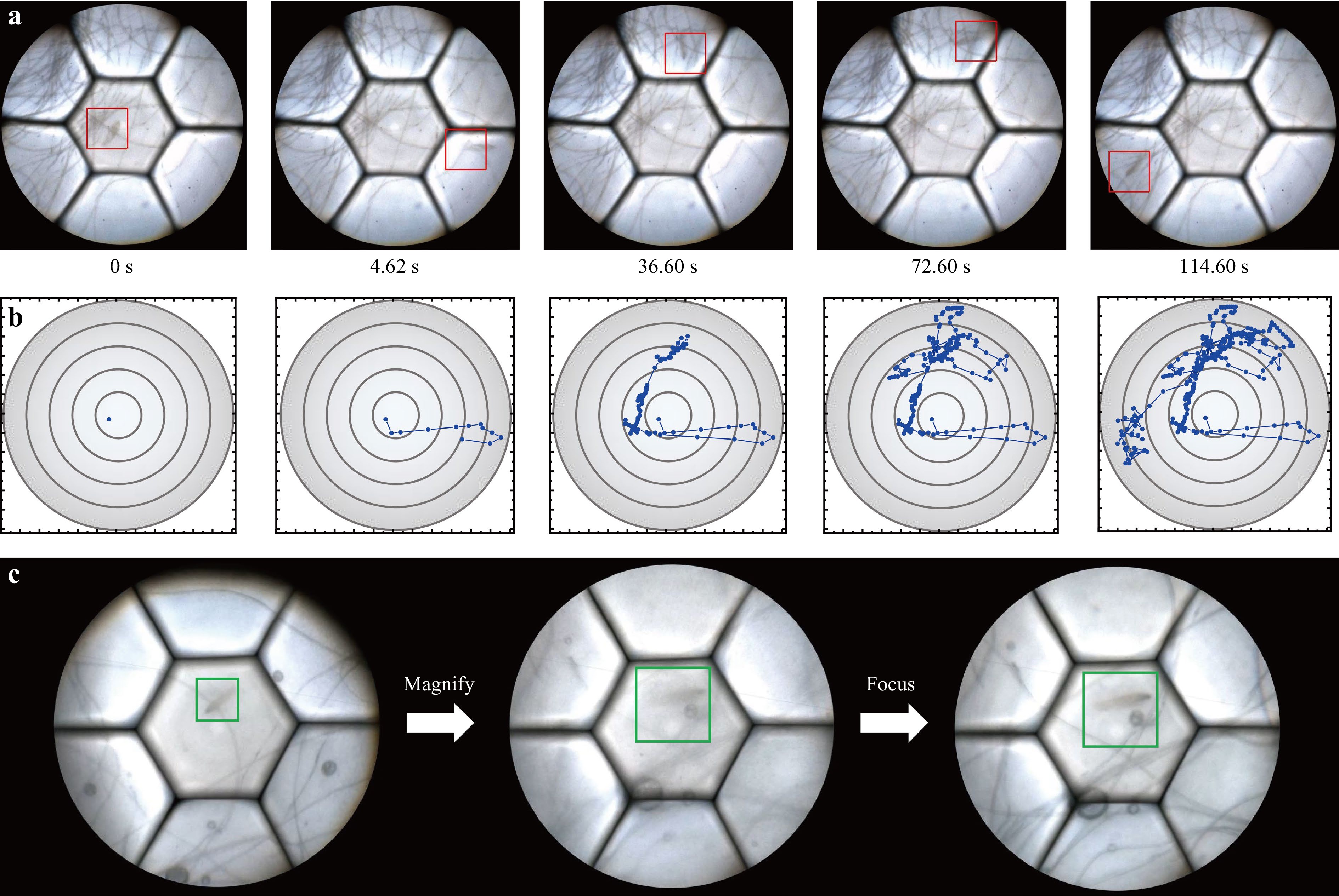
Fig. 8 Real-time imaging of living microorganisms using the AMS microscope. a Motion status of a living paramecium captured by the AMS microscope. b Motion trajectory record of the paramecium. c Imaging of the living paramecium using tracking, fast zooming, and fast WD adjustment functions of the AMS microscope.
$$ \sum\limits_{{S_{ l}}(i,j)} {\left| {{f_{n + 1}}(x,y) - {f_n}(x,y)} \right| \cap \left| {{f_n}(x,y) - {f_{n - 1}}(x,y)} \right|} > T $$ (6) where Sl(i, j) represents a square region with (i, j) as the vertex coordinate; l is the square side length; fn+1(x, y), fn(x, y), and fn-1(x, y) represent the grayscale values of the corresponding pixels in three adjacent frames; and T represents the judgment threshold. We then demonstrated the fast zooming function of the AMS microscope, which can help to enable rapid observation of the details of the paramecium when tracking it (Supplementary Video 4). In contrast, this is difficult to achieve using conventional microscopes. We also demonstrated a fast WD adjustment function that allows clear living microorganism images to be captured during their axial movement (Supplementary Video 5). Supplementary Video 6 and Fig. 8c show the comprehensive use of the tracking, fast zooming, and fast WD adjustment functions for observing living microorganisms. The images in Fig. 8a, c were captured directly from the videos and may exhibit some motion blur. In conclusion, the experiments demonstrated that the AMS microscope has a large FOV and excellent adaptability, which provides great convenience for observing living organisms.
-
Fast zooming, a wide WD range, and a large FOV are expected in modern microscopic imaging, especially in 3D dynamic imaging and large-amount or lager-size sample scanning. It is difficult for conventional methods to achieve all of the above functions without sacrificing spatial resolution or real-time properties. The proposed AMS imaging mechanism provides a solution for achieving a combination of fast zooming, wide WD range, and large FOV on one microscope. It is worth noting that the AMS microscope has potential for further development. By using more sub-lenses and liquid lenses with a larger aperture, the AMS microscope can achieve a larger FOV. By increasing the number of liquid lenses or using liquid lenses with a larger optical power range, the AMS microscope can obtain wider zoom and WD ranges. When the interface curvature of the liquid lens changed, the dispersion coefficient of the liquid material remained unchanged, resulting in chromatic aberration. Upon further increasing the magnification and zoom range of the proposed microscope, chromatic aberration can become an important factor limiting the resolution under white-light illumination. Jointly optimising the parameters of liquid and glass lenses, as well as selecting appropriate lens materials, can contribute to compensating for the chromatic aberration of the total system. In addition, designing achromatic liquid lenses by increasing the number of chambers or interfaces and choosing suitable liquid materials can facilitate chromatic aberration correction. During the experiments, the image acquisition rate of the image sensor was set to 30 frames/s, which meant that the information of the images with different magnifications and WDs could be captured in real time. However, the execution of the algorithms to improve the stitching image quality may be time-consuming; therefore, they were not executed in real time for microfluidic process monitoring and living microorganism imaging. This issue can be addressed through program and hardware optimisations.
-
In summary, we developed an AMS microscope with fast zooming, an extended WD, and a large FOV. Benefiting from the AMS imaging mechanism, the microscope exhibits strong adaptability and enables large information throughput. Experiments demonstrated the advantages of the AMS microscope in pathological sample scanning, thick-sample imaging, microfluidic process monitoring, and the observation of living microorganisms. The proposed AMS microscope is the first step towards zoom multiscale imaging technology and is expected to be applied in life sciences, medical diagnosis, and industrial detection.
-
By considering the fabrication cost and limited required quantity, a compound eye lens (Supplementary Fig. S5d) for the proposed microscope was integrally fabricated using ultraprecision single-point diamond technology, whose fabrication peak-to-valley value was 70 nm. The upper surface of the compound eye lens consisted of seven sub-spherical surfaces with the same radius of curvature of 31.037 mm, the lower surface was spherical with a radius of curvature of 160 mm, and the compound eye lens had an overall diameter of 65 mm. Polymethyl methacrylate was used as the lens material. Assisted diamond grinding technology was adopted to reduce the amount of carving nicks.
-
The effective aperture of the electrowetting liquid lenses used in the proposed microscope was 3.9 mm, and the optical power can change from approximately −15 to 21 D. A liquid lens driver was developed based on STM32G070 (Supplementary Fig. S5e) and supports four channels of synchronous voltage control. Each channel can output a square-wave voltage with a maximum effective value of 65 V and a frequency of ~1.6 kHz. The host computer software was independently developed using Qt Creator and communicated with the liquid lens driver through the computer's USB port. Voltage group data corresponding to different magnifications or WDs can be stored in advance in the liquid lens driver for rapid retrieval.
-
To provide sufficient space for the placement of the image sensors, the total optical length of the microscope was designed to be 442 mm, which required precise installation and adjustment. During the assembly of the microscope, the alignment of the optical axes among the compound eye lens, sub-lenses, and zoom objective is particularly important. We specially designed the assembly and adjustment mechanisms to rotate the collection lens array (Supplementary Fig. S5b) and enable changes in the relative positions of the optical components (Supplementary Fig. S5c). The image sensors were produced by Hikrobot (MV-CA050-20UC), with a 1-inch photosensitive area. The resolution was 2592 × 2048. The seven image sensors used in the microscope were connected to a computer via a seven-channel data stream transmission port (Supplementary Fig. S5f) and transmitted data in parallel. After configuring the modules, including the stage, white-light source, and condenser, the microscope was well integrated (Supplementary Fig. S5a) and is easy to handle.
-
The microfluidic chip (Supplementary Fig. S13b) was processed by BMF Precision Tech Inc. using 3D printing technology; the manufacturing material was a semi-transparent light-yellow resin. There were some small collapses on the upper surface of the microfluidic chip because of the large width of the broadened segment (Supplementary Fig. S14b); however, these did not have a significant impact on the particle flow unless the particles adhered tightly to the upper surface. To enable the particles to be suspended in the solution for a sufficient time, we prepared a high-viscosity dextran solution as a microfluidic solution. The dextran solution was prepared by mixing dextran T500 (Beijing Solarbio Technology Co., Ltd.) and warm water at a mass ratio of 1:10. The material of the particles was cross-linked polystyrene and the concentrations of the red and green particles in the solution were both 2.5 g/L.
-
In the distortion-correction step of image processing, we placed a 10 × 10 chequerboard image with a total side length of 1 mm under seven sub-FOVs in sequence and captured the images with the proposed microscope under different magnifications. Then, we used reverse mapping to correct image distortion, that is, to find the corresponding coordinate position in the original image for each pixel on the corrected image. When performing specific operations, we first marked all vertices and recorded the coordinate mapping positions. Then we connected the marked vertices to form many triangular regions and established the following triangular regional mapping relationships:
$$ \left[ {\begin{array}{*{20}{c}} x \\ y \\ 1 \end{array}} \right] = \left[ {\begin{array}{*{20}{c}} {{x_i} - {x_k}}&{{x_j} - {x_k}}&{{x_k}} \\ {{y_i} - {y_k}}&{{y_j} - {y_k}}&{{y_k}} \\ 0&0&1 \end{array}} \right]\left[ {\begin{array}{*{20}{c}} u \\ v \\ 1 \end{array}} \right] $$ (7) where (xi, yi), (xj, yj), and (xk, yk) are the coordinates of the three vertices of the original graph triangle; (u, v) is the normalised coordinate of any point within the corrected triangular region; and (x, y) is the corresponding coordinate within the triangular area of the original graph. The process and results of the distortion correction are shown in Supplementary Fig. S11.
After distortion correction, although the sub-images can be correctly stitched, the reduction in resolution and illumination owing to spectroscopic effects at the FOV intersections of the centre and edge channels still leads to obvious vignetting. We adopted a composite patching method to process vignetting. First, we patched the vignetted areas at the boundary of the central FOV by transplanting pixels from the corresponding regions at other magnifications and implementing weighted fusion (Supplementary Fig. S12a, b). Moderate brightness adjustments were made during the transplantation. For the vignetted areas at the boundary of the edge FOVs, because of the inability to identify unvignetted areas that could be directly transplanted at most magnifications, we adopted the PatchMatch algorithm to patch the vignetted areas (Supplementary Fig. S12c–e). The main idea of the algorithm is to find the most similar image patch of the area to be patched in the image area that does not need to be patched and then implement a patch. We generated an image pyramid and patched the image from low to high frequencies. Although two frames are required in the composite patching algorithm, compared to entirely adopting the PatchMatch algorithm, the originality of the image is preserved as much as possible.
-
This work was supported by the National Natural Science Foundation of China under Grant Nos. 61927809 and 62175006, Beijing Natural Science Foundation under Grant No. 4222069, and Shenzhen Science and Technology Innovation Commission under Grant No. JCYJ20220818100413030. The authors also thank Prof. Di Wang for her suggestions on the organisation of the paper.
Adaptive multiscale microscope with fast zooming, extended working distance, and large field of view
-
Yi Zheng1,
 ,
, - Xin Wang1,
- Zhao Jiang1,
- Jinbo Xu1,
- Rongying Yuan1,
- Youran Zhao1,
- Haoran Zhang1,
- Chao Liu1, 2, *, ,
-
Qionghua Wang1, 2, *, ,
- Light: Advanced Manufacturing 5, Article number: (2024)
- Received: 09 June 2023
- Revised: 16 January 2024
- Accepted: 16 January 2024 Published online: 07 March 2024
doi: https://doi.org/10.37188/lam.2024.008
Abstract: The field-of-view (FOV), depth of field, and resolution of conventional microscopes are constrained by each other; therefore, a zoom function is required. Traditional zoom methods lose real-time performance and have limited information throughput, severely limiting their application, especially in three-dimensional dynamic imaging and large-amount or large-size sample scanning. Here, an adaptive multiscale (AMS) imaging mechanism combining the benefits of liquid lenses and multiscale imaging techniques is proposed to realize the functions of fast zooming, wide working distance (WD) range and large FOV on a self-developed AMS microscope. The design principles were revealed. Moreover, a nonuniform-distortion-correction algorithm and a composite patching algorithm were designed to improve image quality. The continuous tunable magnification range of the AMS microscope is from 9× to 18×, with the corresponding FOV diameters and resolution ranging from 2.31 to 0.98 mm and from 161 to 287 line-pairs/mm, respectively. The extended WD range is 0.8 mm and the zoom response time is 38 ms. Experiments demonstrated the advantages of the proposed microscope in pathological sample scanning, thick-sample imaging, microfluidic process monitoring, and the observation of living microorganisms. The proposed microscope is the first step towards zoom multiscale imaging technology and is expected to be applied in life sciences, medical diagnosis, and industrial detection.
Rights and permissions
Open Access This article is licensed under a Creative Commons Attribution 4.0 International License, which permits use, sharing, adaptation, distribution and reproduction in any medium or format, as long as you give appropriate credit to the original author(s) and the source, provide a link to the Creative Commons license, and indicate if changes were made. The images or other third party material in this article are included in the article′s Creative Commons license, unless indicated otherwise in a credit line to the material. If material is not included in the article′s Creative Commons license and your intended use is not permitted by statutory regulation or exceeds the permitted use, you will need to obtain permission directly from the copyright holder. To view a copy of this license, visit http://creativecommons.org/licenses/by/4.0/.

 DownLoad: