


-
Holography is a methodology based on coherent light that can fully describe the optical field. Although, the concept was invented in the late 40's, optical holography did only advance with the development of the laser in the 60's. Holography is a two step method, consisting of an interferometric recording and a reconstruction step. Its ability to capture, measure and reproduce any given wavefield, has made it useful in a broad range of applications. Examples are extended depth-of-field microscopy via digital holographic microscopy1; state-of-the-art surface characterization of complex objects (e.g. large mirrors, aspheric optics, biological specimens) via holographic interferometry2, and the visualization of 3D content3.
-
Most relevant for the latter case, holography has the remarkable property of being able to reproduce all known natural visual depth cues4, such as:
occlusion provides depth information as front objects occlude more distant objects.
eye accommodation derives depth from the ring muscle tension around the lens of the human eye.
(con-)vergence derives depth from the gaze angle of the eyeballs.
stereopsis derives depth from the differences in between the two monocular images of our eyes. The differences are due to the inter-pupillary distance.
All depth cues can be observed in holographic displays with the naked eye and can therefore, in theory, reproduce a faithful 3D representation of any given scene without restrictions on the scene contents. This sets holography apart from other plenoptic imaging methods. Namely, stereoscopic or lightfield imaging fundamentally suffer from the accommodation-vergence conflict, caused by a mismatch between the fixed focal distance of the optical/virtual image (accommodation cues) produced by the display, and the perceived rendered scene-dependent 3D object distances (vergence cues). Volumetric imaging does not have this conflict, but on the other hand can only offer constrained finite render volumes and requires workarounds for occlusions in the rendered volume.
With the advent of the digital revolution, digital holograms (DH)s became possible. DHs consist of matrices of typically scalar complex numbers, which are mapped on some surface upon creation and reconstruction. They are created either through capture in optical setups, for example by charged-coupled-devices based camera sensors, or through numerical calculations on a computer, i.e computer generated holography (CGH). Subsequently, limited viewing or partial rendering is possible on conventional 2D or lightfield displays through numerical reconstruction of specific view-points. For a 3D scene reproduction, the modulation of light dictated by a DH needs to be discretized and printed5,6 or programmed into a refreshable spatial light modulator devices (SLM). An important requirement for the consumption of 3D scenes, is a sufficiently high space-bandwidth product (SBP) of the modulation medium. The SBP is defined as the product of maximal viewing angle and maximal scene size. Thus with a small SBP either the viewing angle or scene size remains limited. For a modulation pattern of
$ N \times N $ features with inter-feature distance p, the SBP is equal to$ N^2 $ , as the spatial extent of the observed scene is limited by the size of the modulated area$ Np $ , whilst the maximal spatial frequency given as$ p^{-1} $ . -
The most relevant technology is refreshable SLM-based holographic displays, as they allow for holographic user interfaces and convenient consumption of holographic content. Since holography leverages diffraction, p is required to be of the order of the wavelength λ of the illuminating laser (i.e typically ranging from
$ \sim0.5\lambda $ to$ \sim 10\lambda $ ) — while ensuring a sufficiently large SBP. This poses significant technical challenges, for the signal processing backbone, the display support electronics as well as for the SLM itself. Therefore, three display usage scenarios3 have emerged.Head-mounted displays ease the SBP requirements by bringing the SLM close to the eye(s) of a single observer. In that case, only a small area is required per eye – covering the entire eye-box. On top of that, the SLMs in this configuration only need to support a limited field-of-view due to the limited motion range of the eye. Examples are detailed in4,7,8, particularly Microsoft's HoloLens 1.
Eye-tracking supported displays combine an SLM of limited SBP with beam steering facilitated by eye-tracking and active adaptive optics in order to emulate a large SLM for a single to few observer(s). A famous exemplary implementation is by SeeReal9.
Full-parallax displays do not reduce the SBP and are providing the maximal supported field-of-view to a theoretically unlimited number of observers. As the required SBP for this scenario is in the order of giga to tera-pixels, they became approachable through first prototypes of metasurface DHs10 only recently.
Aside from these principal scenarios various variations and combinations exist. The geometry can be planar, curved, or cylindrical; this can be realized both by the display device11 or by the coherent illumination source wavefront shape12. A full-parallax displays may take the shape of a flat "window", not unlike a television13, or of a 360° table-top display14. Important to mention is that many unrelated display technologies are incorrectly referred to as "holographic", such as the "Pepper's ghost illusion" or "holographic pyramid". These consist of conventional projection systems and do not show 3D images nor use any modulation with coherent light.
-
Digital holography is a non-contact measurement technique enabling highly accurate 3D object measurements. It can capture the complete complex-valued optical field, allowing for e.g. post-capture numerical processing such as refocusing or aberration correction. This has many applications besides recording 3D objects for display, such as 3D measurements for microscopy15, 3D particle and flow measurements16, biological specimens17, and 3D object recognition18.
The basic setup diagram is shown in Fig. 1, where an expanded laser beam goes through a beamsplitter and gets divided into a reference beam and an object beam. The latter will illuminate the object of interest to be recorded. Both beams are then optically recombined and form an interference pattern that can be registered nowadays with a CMOS or CCD camera sensor. This encoded information can be numerically processed to obtain the complex-valued hologram.
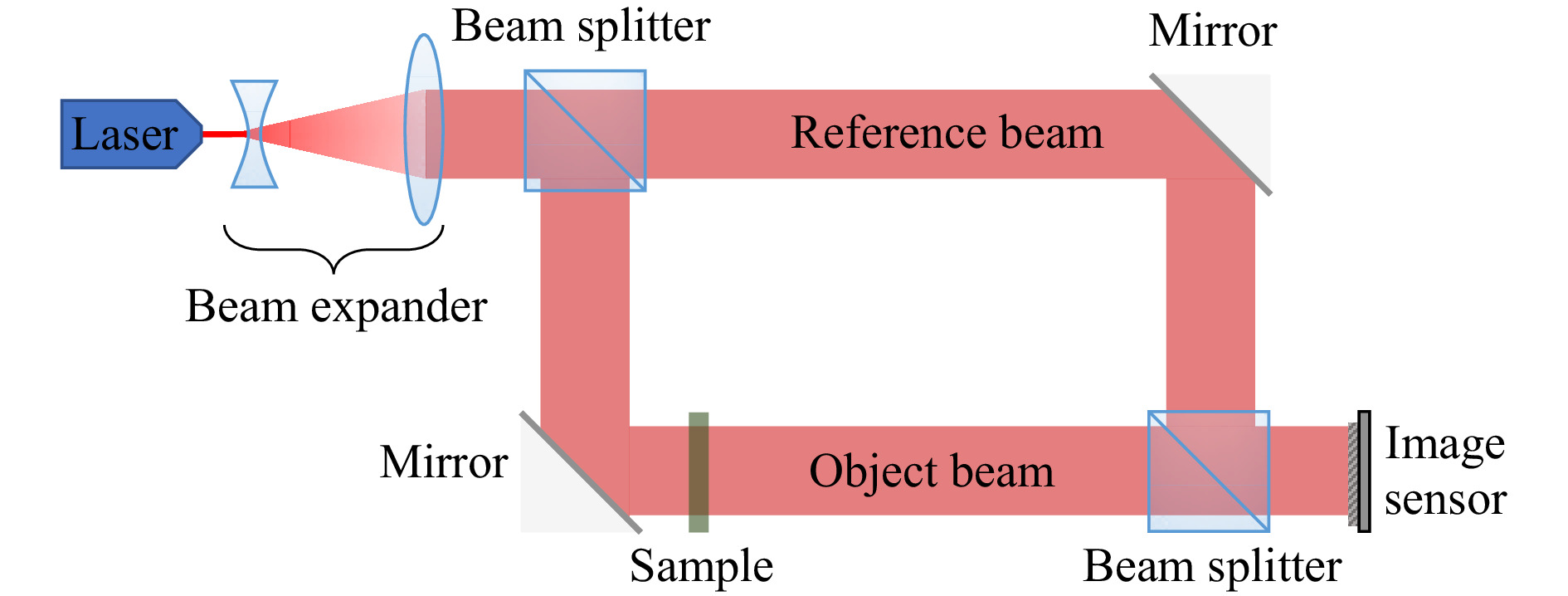
Fig. 1 Simplified diagram of a holographic on-axis recording setup in transmission mode3.
These setups come in many forms2, with various capabilities and trade-offs. Among many others, there are setups using holographic tomography19, combining recorded holograms with CGH20, single pixel imaging21, Fourier horizontal parallax for high resolutions22, and single-shot multiplexing23.
Unfortunately, recording 3D objects that way for subsequent display on a holographic displays is not very flexible: (1) limitations on scene types prevent the capture of large objects, especially outdoors or dynamic scenes with moving objects, which would have to be illuminated with a stable coherent laser source without intrusion of other light; (2) no virtual content is supported; (3) the resolution capabilities of CCD/CMOS chips are modest, requiring complex multiplexing solutions to reach the requisite sample counts for detailed 3D scenes; and (4) the holographic display setup parameters vary a lot between systems (pixel pitch, resolution, wavelength, optics, etc.). CGH can address all these shortcomings, which will be the main focus of this paper.
-
Irrespective of the used display, vast numbers of suitable DHs can only be created through CGH which models the propagation of light emitted by a given scene onto a virtual hologram (recording) plane. In this paper, we review the challenges that CGH faces and the state-of-the-art approaches that have been proposed to counter various of those challenges. The principal trade-off is between rendering the most realistic scene and achieving the objective in an acceptable time. Realistic rendering comprises textures, structural surface properties, non-homogeneous lighting, and occlusions required to improve realism and the immersion of the observer. Various CGH techniques are limited in the effects they can faithfully model; in general, graphical effects have to be re-designed for CGH due to substantially different intrinsic representation of numerical diffraction compared to their conventional computer graphics (CG) counterparts. The most realistic CGH is currently achieved by leveraging ray-tracing, but effects such as refractive optics or true mirrors, may require new conceptual approaches altogether.
Highly realistic CG for photographic imagery is already computationally challenging, but CGH is unfortunately still several orders of magnitude more complex to compute. This is because of three main reasons. Firstly, the diffraction integral, which describes said propagation of light, is a highly non-local many-to-many mapping leading to lots of random memory accesses and updates. Secondly, state-of-the-art DHs of acceptable quality require large resolutions of at least 108 pixels. For example, a single monochrome high quality hologram of size 10 × 10 cm and a 60° field of view would require the modulation, computation, and signaling of 326000 × 326000 pixels. Thirdly, CGH operates most of the time internally with a high-bitdepth complex-valued representation for accurately modeling light propagation.
In face of these resolutions even current CPU-based hardware is computationally-, memory- and/or, bandwidth-bound. Therefore, specialized, alternative hardware architectures such as graphic processor units (GPU)s and field programmable gate arrays (FPGA)s are increasingly studied for CGH.
-
In this paper, we review the state-of-the-art in CGH without limiting ourselves to any particular class of CGH algorithms. That said, there is no unique way of classifying the algorithms in existence. We propose to discern between the basic element representation (e.g. wavelets, points, polygons), algorithmic acceleration (e.g. look-up tables, sparsity based approaches, deep learning based accelerations) and hardware accelerations (e.g. low precision calculations, GPU or FPGA based architectures). Using this, we arrive at a simple classification of CGH methods based on representations in the following section. Thereafter, we study concepts of algorithmic accelerations, which may be found or combined with several of the aforementioned CGH methods. In the next section, we discuss the joint optimization of hardware and CGH approaches before discussing the closely related challenges of preparing content for SLM-based holographic displays. This includes the compensation of SLM specific limitations, complex-amplitude encoding (on typically only real-valued modulation SLMs), image quality enhancement, and visual quality assessment. The paper will end with a conclusion of our findings.
-
The behavior of light in free space (or any linear, isotropic, homogeneous, non-dispersive medium) is governed by the vectorial Helmholtz equation. Moreover in holography, we are primarily working in a regime, where the diffracting aperture and propagation distances are large compared to the wavelength. In that case scalar diffraction theory is sufficiently accurate. For a monochromatic light source (e.g. a laser), the electromagnetic wavefield can be characterized by a scalar field, assigning a single complex-valued number to every point in space. The amplitude corresponds to the magnitude of the electric field, while the phase described the relative phase delay w.r.t. the reference wave. This assumption can be made because the light source is highly monochromatic, so the relative phase delay can be considered constant during the recording of a static hologram or a single holographic video frame.
Scalar diffraction can be modelled accurately by the Rayleigh-Sommerfeld model24, where the object wavefield in the hologram plane H can be calculated for every
$ {\bf{x}}\in H $ :$$ H({\bf{x}}) = \frac{1}{i\lambda}\iint_SU({\bf{p}})\frac{e^{ik \lVert {\bf{p}}-{\bf{x}} \rVert}}{\lVert {\bf{p}}-{\bf{x}} \rVert^2} \: {\bf{n}} \boldsymbol{\cdot} ({\bf{p}}-{\bf{x}})d{\bf{p}} $$ (1) where
$ {\bf{p}}\in S $ are emitting points on a surface S with amplitude function U over which is integrated.$ {\bf{n}} $ is the surface normal of S in$ {\bf{p}} $ , k is the wave number and i is the imaginary unit. The object wavefield is up to a global phase constant identical to the full hologram, if the reference wave is a plane wave with normal incidence angle. For simplicity and convenience, we consider in this paper the frequently used assumption of the reference wave to be a normally incident plane wave identical to 1.To account for occlusions, one can utilize the Huygens–Fresnel principle, where secondary point source wavelets get stimulated at occlusion boundaries. Unfortunately, this generic formulation is not useful in practice, as the many-to-many mapping between all emitters
$ {\bf{x}} $ and hologram points$ {\bf{p}} $ grows exponentially. Compounded with the large resolutions and video frame rates needed for digital holograms for display systems, this direct approach is too computationally demanding or even intractable for all but the simplest holograms.To achieve efficient CGH suitable for (near) real-time computation, one must introduce various approximations. Multiple solutions to this problem were proposed and refined over the past decades, trading off visual fidelity, supported visual effects and calculation time. In the remainder of this section, we classify these different approaches based on their primary decomposition into simpler constituent elements.
-
One of the most widely used CGH techniques is the point cloud method 25. This is achieved by discretizing Eq. 1 by means of sampling the surfaces S and amplitudes U. Given points
$ \{{\bf{p}}_1, ..., {\bf{p}}_N\}\in S $ with corresponding amplitudes$ \{a_1, ..., a_N\}\in \mathbb{C} $ , we get$$ H({\bf{x}}) = H(x_h,y_h,z_h) = \sum\limits_{j=1}^N \frac{a_j\exp{\left(ik \lVert {\bf{p_j}}-{\bf{x}} \rVert\right)}}{\lVert {\bf{p_j}}-{\bf{x}} \rVert} $$ (2) where we assume without loss of generality that the hologram plane coincides with the
$ xy $ plane, so that$ {\bf{x}} = (x_h, y_h, z_h=0) $ . These spherical wavefronts can often be accurately approximated by parabolic wavefronts. This is known as Fresnel approximation$$ H(x_h,y_h) = \sum\limits_{j=1}^N a_j\exp\Big(\frac{\pi i}{\lambda z_j}\big[(x_h-x_j)^2 + (y_h-y_j)^2 \big]\Big) $$ (3) where
$ {\bf{p}}_j = (x_j, y_j, z_j) $ , ignoring the attenuation factor$ {\exp{\left(2\pi i/(\lambda z_j)\right)}}/{i\lambda z_j} $ in most point-cloud methods, as this will generally not noticeably affect the perception of the hologram; it can optionally be included for improved accuracy. The wavelength is denoted λ, so that$ k ={2\pi}/{\lambda} $ . The Fresnel approximation has the important property of being separable, facilitating its use to analytically solve more complex diffraction problems, besides being considerably easier to compute. This approximation can be obtained using a truncated Taylor expansion, valid whenever$ z\gg\lambda $ and when considering relatively small diffraction angles θ where$ \theta\approx\sin\theta $ holds. This will be satisfied in practice whenever the pixel pitch p is at least a few times larger than the wavelength (roughly when$ p\ge 4\lambda $ ), or when the subtended angle of objects on the hologram is sufficiently small, i.e under paraxial viewing conditions. Otherwise, the paraxial approximation introduces noticeable distortions.In principle, any 3D scene can be approximated to arbitrary accuracy using enough points. Thanks to their generality and simplicity, point-cloud methods are one of the most widely used methods. An example diagram is shown on Fig. 2. Nevertheless, naively executing Eq. 2 is still very costly, as every sampled point
$ {\bf{p_j}} $ will result in updates to each hologram pixel. This process can be sped up by using different acceleration techniques26–28 as described in a latter section. However, infinitesimal points are not ideal for describing surfaces to model occlusions and light reflection properties. Moreover, individually calculating points can be sub-optimal in cases where objects can be well-described by a few more complex primitives.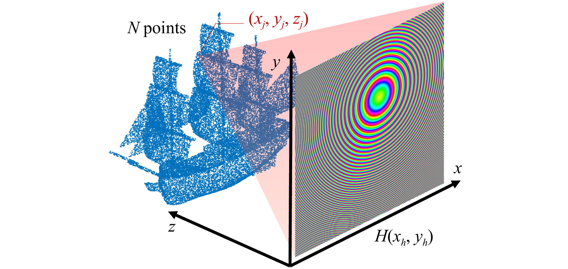
Fig. 2 Diagram of the point-cloud CGH algorithm, showing typical axis conventions. Every point
$(x_j,y_j,z_j)$ of the ship model point cloud creates a PSF on the hologram plane (color code: hue corresponds to phase, brightness to amplitude). A sum over all PSFs yields the final hologram. -
Holograms can be generated with elements more complex than point spread functions (PSFs). In many cases, 2D and 3D objects can be decomposed into a relatively small number of basis elements which can be efficiently computed. This is achieved by formulating solutions for some restricted set of shapes S and complex amplitude distributions U in Eq. 1. We consider two approaches: analytical methods and precomputed basis function methods.
Analytical methods attempt to solve Eq. 1 analytically (sometimes with approximations) for certain shapes or surfaces, such as lines29,30, curves31, and polygons32,33. The latter have been augmented with partial support for textures as well34,35. This allows for directly calculating the corresponding hologram wavefield in each pixel, which would otherwise require summing thousands to millions of points for achieving the same effect.
One drawback is that analytical models will necessarily limit the system’s degrees of freedom, precluding the use of highly complex textures or light emission patterns. We posit that these methods are best used as scene building blocks in conjunction with other methods rather than in isolation.
Another similar technique precomputes diffraction patterns, e.g. as emitted textured surface patches with different light distributions, and stores them in look-up tables (LUT)s. This is often combined with layer-based methods or wavefront recording planes (see next sections) to reduce the LUT memory footprints. In order to increase realism and supported effects, instances of elements can be precomputed at many orientations, axial positions36, light distributions37, and in multiple phase noise instantiations thereby reducing unwanted visual artifacts38. They can even be used for precomputing occlusion patterns, although these are more limited and less accurate due to being a non-linear and non-stationary filter effect. We will discuss more details in a subsequent section. For the right scene compositions and hologram display properties, this can achieve highly realistic effects. One main limitation is the inherent discretization of the phase space and the exponential growth of look-up table sizes with the number of variables under consideration.
-
When S is a plane, we can rewrite Eq. 1 as a convolution because of the translational symmetry along the
$ xy $ -plane. This is desirable, since convolutions can be computed efficiently using the Fast Fourier Transform (FFT). For a wavefield parallel to the$ xy $ -plane displaced at a distance$ d \neq 0 $ with the complex-valued amplitude function U, we have that$$ H(x,y,0) = U(x,y,d) * \frac{\exp{\left(ik \sqrt{x^2+y^2+d^2} \right)}}{\sqrt{x^2+y^2+d^2}} $$ (4) where * is the convolution operator. The transfer function can be computed directly in Fourier space; this method is called the angular spectrum method (ASM)24:
$ H(x,y,0) = $ $$ {\cal{F}}^{-1}\left\{ {\cal{F}}\left\{ U(x,y,d) \right\} \exp{\left(i{2}\pi d \sqrt{\lambda^{-2}-\omega^2-\eta^2} \right)} \right\} $$ (5) where
$ {\cal{F}}\{\cdot\} $ and$ {\cal{F}}^{-1}\{\cdot\} $ respectively denote the forward and reverse Fourier operators, transforming between spatial$ (x,y) $ and frequency$ (\omega,\eta) $ coordinates.Multiple variants and extensions to convolutional propagation exist besides the ASM. The Fresnel approximation can also be used here to obtain a separable quadratic phase kernel41. Shifted diffraction algorithms42 allow for off-axis diffraction of plane segments, variants allowing for different pixel pitches at source and destination planes, or even tilted diffraction algorithms43 where source and destination planes do not need to be parallel.
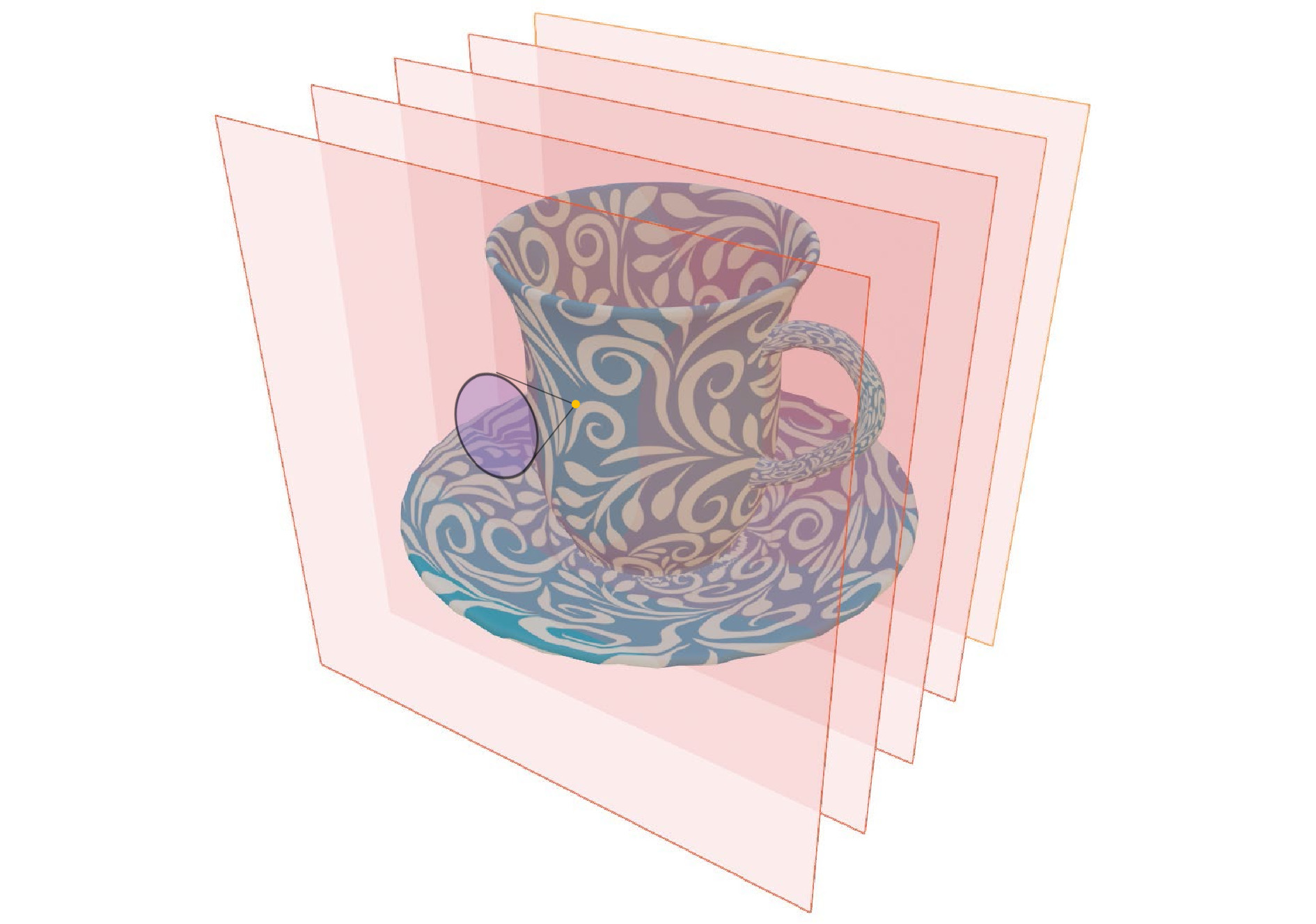
Layer-based algorithms subdivide the scene into multiple layers, where each scene element is allocated to a specific plane, typically the closest one (cf. Fig. 3). Then, the plane wavefield can be numerically diffracted efficiently to the hologram plane by means of convolutional propagation. Because of the elements’ proximity, only a fraction of the emitted light angles will reach the hologram plane, thereby requiring to only update a small subset of all hologram pixels, benefiting calculation speed (this is closely tied to the usage of wavefront recording planes, see later sections). Moreover, since one has access to the wavefield volume at multiple depth planes, one can easily simulate occlusion and transparency operators by suppressing the amplitude at the sections where the planes intersect with the virtual objects.
Examples of these approaches are RGB+depth methods44, utilizing a quantized depth map as a guide to assign points to their respective layers or multi-layer propagation methods. The latter precomputes basis functions and occluders36 thereby optimizing both the number of layers and their mutual distances and reusing the precomputed propagation kernels. Another related way of achieving variable depth is to non-uniformly resample a layer for a more continuous change in depth45.
Layer based methods are efficient CGH techniques, often requiring local updates and providing more straightforward ways of applying occlusion. In their base form, they are less suitable for extreme-resolution holograms due to their linearithmic complexity, as well as having difficulties to efficiently model effects at steep viewing angles.
-
Polygon-based CGH methods are inspired by conventional computer graphics, where objects are represented by 3D meshes of triangles with associated textures maps and material properties. Because polygons are by definition confined to a plane, one can use convolutional diffraction methods to propagate the polygonal wavefield towards the hologram plane. We designate a polygon method as “general” to differentiate it from the analytical polygon methods32 described in the geometric primitives section. Two major challenges in polygon-based CGH are the efficient and accurate calculation of (1) the source wavefield in the polygon plane and (2) the polygon interactions, e.g. due to mutual occlusions.
In46, polygons are first expressed in their local coordinates. Their light emission depends on the combination of surface material and the relative position of virtual light sources. It will result in diffuse and specular light components, which have a particular spectral envelope (cf. Fig. 4). This can be realized by using e.g. random phase to induce a uniform spectral response, with subsequent filtering for the specular component47. Once the polygon wavefield is calculated, it needs to be aligned to be parallel with the hologram plane before convolutional propagation is possible. This requires a rotational transform of the wavefield, which can typically be expressed by resampling the Fourier domain of the wavefield43.
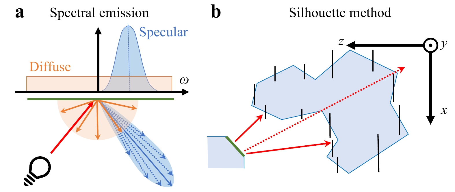
Fig. 4 Concepts from polygonal CGH. a diffuse (orange) and specular (blue) emission functions with corresponding spectral envelopes; b an exemplary polygon (green) may emit light rays that will erroneously evade occlusion (dotted red ray).
To model occlusion, the wavefield can be propagated from back to front, progressively occluding pieces of the wavefield like layer-based methods. The silhouette method48 does this by creating a mask at the center of every polygon, being the orthogonal projection of each (rotated) polygon's shape along the optical axis parallel to the
$ xy $ -plane. This creates small "billboards" shielding the light of the advancing wavefield. The approach works well for holograms with small viewing angles and mostly convex shapes, but can cause in more general holograms with complex 3D models light to leak into the final DH. The issue can be addressed e.g. with the "switch-back" method49 which, in turn, requires more calculations.Polygon-based CGH can create realistic graphics with accurate occlusion. Its computational efficiency is highly dependent on the polygon count. Because it accurately models diffraction, it can be combined with other CGH methods. A drawback is the requirement of many FFTs, which is hard to scale and optimize when computing high-resolution holograms. It may be somewhat mitigated by only propagating over small distances, to limit the spreading of light across the hologram. Another drawback is that complex lighting effects such as global illumination, soft shadows, ambient occlusion, refraction, etc. are hard to model, as they would require many costly propagations back-and-forth between polygons.
-
Ray tracing is a computer graphics technique for modeling light transport. The main idea is to track individual rays of light bouncing through the virtual scene and interacting with materials, accurately computing the amount of light reaching every pixel of the virtual camera. With the right models, one can achieve photo-realistic rendered images indistinguishable from actual photographs nowadays.
These techniques can be leveraged in CGH to model light transport as well. However, it cannot be utilized straightforwardly, since holography is fundamentally wave-based, differing substantially from ray-based models.
One major problem is that unlike in computer graphics where a single view is rendered, in holography we aim to obtain a continuum of viewpoints, requiring to model incoming light from many angles rather than only from the camera pinhole. A second major problem is the lack of phase coherence: the phase is sensitive to distance changes which are only a fraction of the wavelength, i.e. several nanometers. This means that cast rays from neighboring pixels at similar angles will almost never reach the exact same point, causing mismatching phase which will significantly degrade visual quality. This is exacerbated by the limited precision of 32-bit floating-point numbers, whose machine epsilon is
$ \approx 10^{-7} $ . That means that those ray-tracing methods have to be adapted or combined with other CGH algorithms to be utilized effectively.In52, the hologram was computed with backward ray-tracing from hogels (sub-holograms containing angular ray information) outward, or in combination with multiple WRPs53. That way, advanced shading effects can be leveraged with a similar pipeline to conventional CG, creating realistic holograms. However, this approach does not address the second problem of phase coherence.
More recently, a solution was proposed combining point-based CGH with path tracing to address the phase coherence problem50. The scene was adaptively sampled into points, after which the light distribution was measured in every point using the ray-tracing simulation. That way, complex effects such as soft shadows, reflections and ambient occlusion could be accounted for, all with sharp focal cues. Then, modulated PSFs with occlusion were propagated to the hologram plane. (see some examples in Fig. 5)
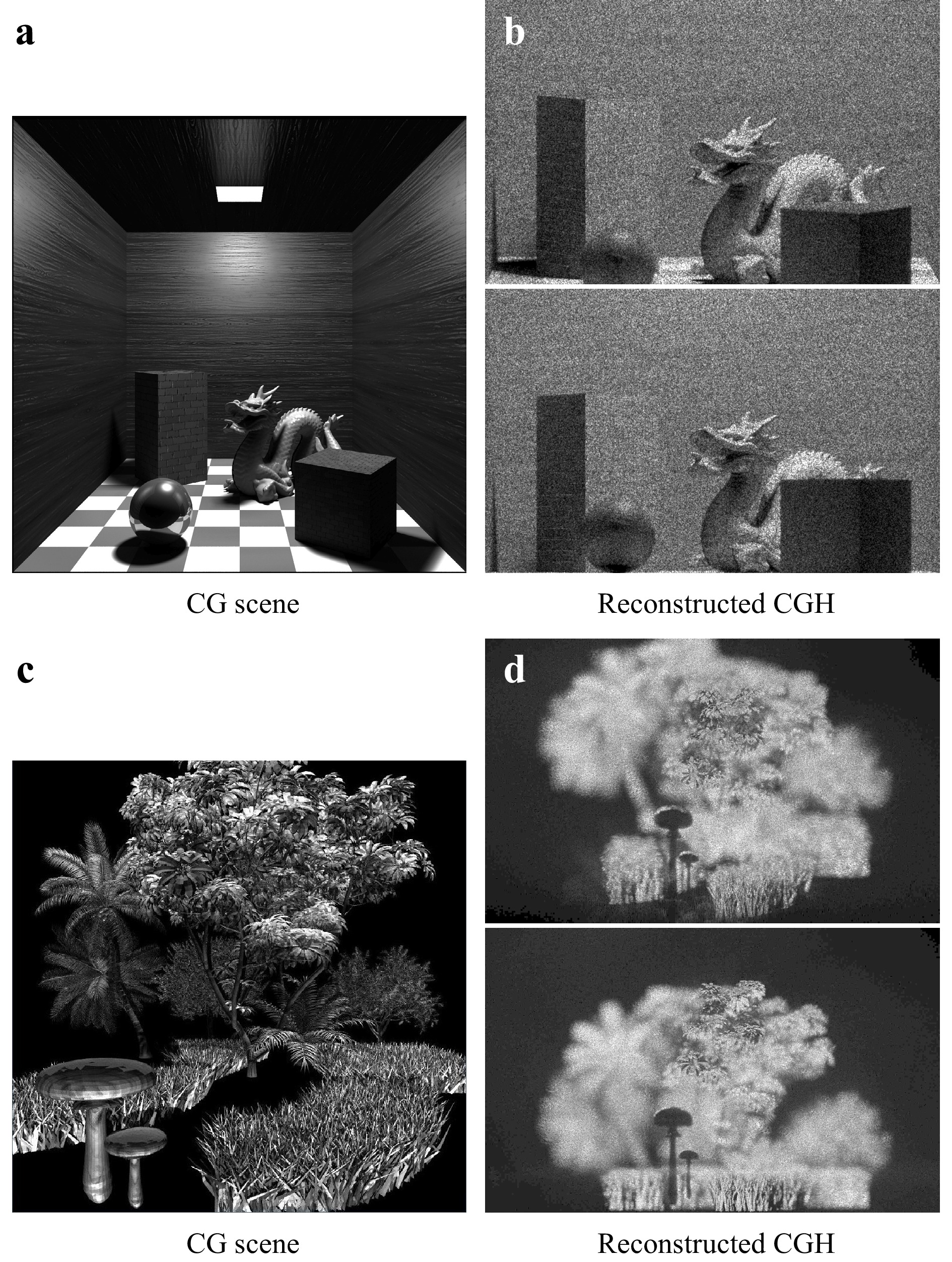
Fig. 5 Examples of virtual scenes (a,c) and views taken from the corresponding CGH (b,d). (a,b) is a Cornell box, showing the use of are light, with soft shadows and global illumination (Source:50,51). (c,d) is a grass and forest scene created from detailed 3D meshes, showcasing intricate occlusions and shadows.
The main advantage of ray-tracing CGH is the ability to reach high realism, and its compatibility with modern graphics hardware such as the latest NVIDIA RTX series with ray-tracing units. These DHs can serve as reference data or ground-truth. One important drawback is the high computational cost, making it unsuitable for real-time calculation of large holograms or complicated scenes without significant approximations in the near future.
-
Aside from computational challenges, which will be considered in the next section, CGH methods suffer from a structural problem. That is, visual effects need to be frequently re-implemented separately for each CGH method and rarely any single method can offer all relevant effects. Depending on the CGH method, occlusion, shadows, material properties such as textures/surface roughness, and non-uniform lighting such as via the Phong model37 are more or less challenging to implement — see Table 1. For example, occlusions and shadows are a problem when working with points of infinitesimal extent. In contrast, it's easy to model point-wise non-uniform lighting as well as material properties – described in each point typically by a bi-directional reflection distribution function (BRDF).
Category Method Point-clouds Geometric primitives &
basis functionsLayer-based Polygon-based Ray-tracing Texture support Yes Limited Yes Yes Yes Non-uniform scene lighting Medium Hard Limited Hard Easy Shadows Hard Hard Limited Medium Easy Occlusion Hard Hard Easy Medium Easy Primitive super-sampling No Yes Yes Yes Yes Supported scene complexity (object count) Low High High Low-Medium High Support object detail High Medium High Low High Support for wide & viewing angles Yes Limited No Yes Yes Computation speed Slow-Medium Fast-Very Fast Fast Medium Slow Implementable on specialized hardware Easy Easy Hard Hard Limited Table 1. CGH algorithm classification summary
Advanced effects such as true reflections, that is reflections coming into focus at an out-of-mirror plane upon reconstruction of the DH, and refraction by objects, for example focusing lenses are currently not well studied with any method. The reason is that they require modeling of reflecting and refracting wavefields in complicated ways. A naive approach would require the computation of an interim hologram of the entire visible scene at each surface.
Another challenge is the typically large number of degrees of freedom in each CGH method. Because of insufficiently correlated objective quality metrics in holography (see last section of the paper) and unclear parameter bounds, it still remains unclear which parameter ranges correspond to which visual quality and where trade-offs for the sake of computational complexity can be done. Especially so, when porting methods to different hologram and scene parametrizations.
Finally, as was pointed out before, hybrid CGH methods also hold big promise in terms of visual quality versus computational complexity, since they can combine the best aspects of several methods54.
-
As the previous section already indicated, one major consideration in using any CGH algorithm is computational complexity. Therefore, several acceleration techniques of the CGH methods have been developed. Any of the acceleration techniques below has been combined in literature already with one or more of the CGH algorithm classes defined in the previous section. In this section we discuss: several ways to reduce the signal complexity in specific, so-called sparse, representations; the re-use of precomputed results; dynamic CGH acceleration; and deep-learning supported CGH.
-
Sparsity is a concept in signal processing, whereby a signal can be modelled by a relatively small number of significant coefficients when expressed in the right transform space.
This can be used for sparse approximations, where a few percent of the total coefficient count account for the vast majority of the signal's energy. The sparsity concept is used in remote and compressed sensing, in the compression of signals, in deep learning, signal filtering (most common: low-pass filtering), and finally also efficient/sparse computation.
In CGH, the notion of sparsity can be leveraged to significantly reduce computational requirements because of the nature of diffraction as expressed in Eq. 1. Generally all pixels in the hologram plane will be affected by elements in the scene, requiring many updates. But by computing the hologram in a transform domain where the signal is sparse, only a few coefficients need to be updated to compute CGH elements. For a transform
$ {\cal{T}} $ , a linear combination of elements$ E_j(x,y), \forall j \in \{1,..,N\} $ (e.g. PSFs, basis functions, polygons, etc.) can be rewritten as$$ H(x,y) = {\cal{T}}^{-1}\big\{{\cal{T}}\{H(x,y)\}\big\} = {\cal{T}}^{-1}\Bigg\{\sum\limits_{j=1}^N {\cal{T}}\{E_j(x,y)\} \Bigg\} $$ (6) For effective sparse CGH several requirements must be met.
High sparsity, i.e. the ratio of needed transform coefficients to total hologram pixel count must be small, so to accurately approximate the target signal with few updates.
Efficient computation of the coefficient values of the different elements
$ {\cal{T}}\{E_j(x,y)\} $ directly in transform space. They should not be much more costly than evaluating$ E_j(x,y) $ values in the hologram plane for acceleration to be possible.Efficient (final) inverse transform
$ {\cal{T}}^{-1} $ , with a computational complexity that is low compared to conventional CGH algorithms.An important distinction to make is that it is not necessarily the hologram itself that needs to be sparse in transform space, but rather the individual elements
$ E_j $ themselves. E.g. in point-cloud CGH, the individual PSFs must be sparse in$ {\cal{T}} $ for acceleration to be possible, but their superposition does not have to be. Note, that one can use multiple different transforms, in parallel or cascaded, as well as overcomplete transforms (i.e. with more transform coefficients than hologram pixels) so long as the above requirements are met.Although not originally characterized a such, many CGH acceleration techniques can be retroactively considered sparse techniques. We make a further classification depending on the chosen transform
$ {\cal{T}} $ and how the coefficients are computed. -
Interim wavefront recording planes (WRP)s are one of the most widely used CGH acceleration techniques, which is a sparse CGH method where
$ {\cal{T}} $ is a convolutional diffraction operator. When the distance of virtual scene elements to the WRP are small, the diffraction pattern will be energetically highly spatially localized, meaning only few coefficients need to be updated. For point cloud algorithms, the relevant pixels to be updated can be found using the relationship$ \sin(\theta)=\lambda\nu $ between a diffraction angle θ w.r.t. the hologram plane normal and the signal's spatial frequency ν. This means the maximum diffraction angle$ \theta_{\max} $ is determined by the Nyquist rate,$$ \sin({\theta}_{\max}) = \lambda\nu_{\max} = \frac{\lambda}{2p} $$ (7) governed by the pixel pitch p and the illuminating wavelength λ. WRP coefficients at steep angles need not to be updated because either (1) they induce frequencies in surpassing
$ \nu_{\max} $ which would cause aliasing, or (2) they produce signals which will never reach the final hologram. In the former case, one can use the geometric relationships between the emitting point and its distance d to the WRP (cf. Fig. 6a) to determine the corresponding PSF width on the WRP to be equal to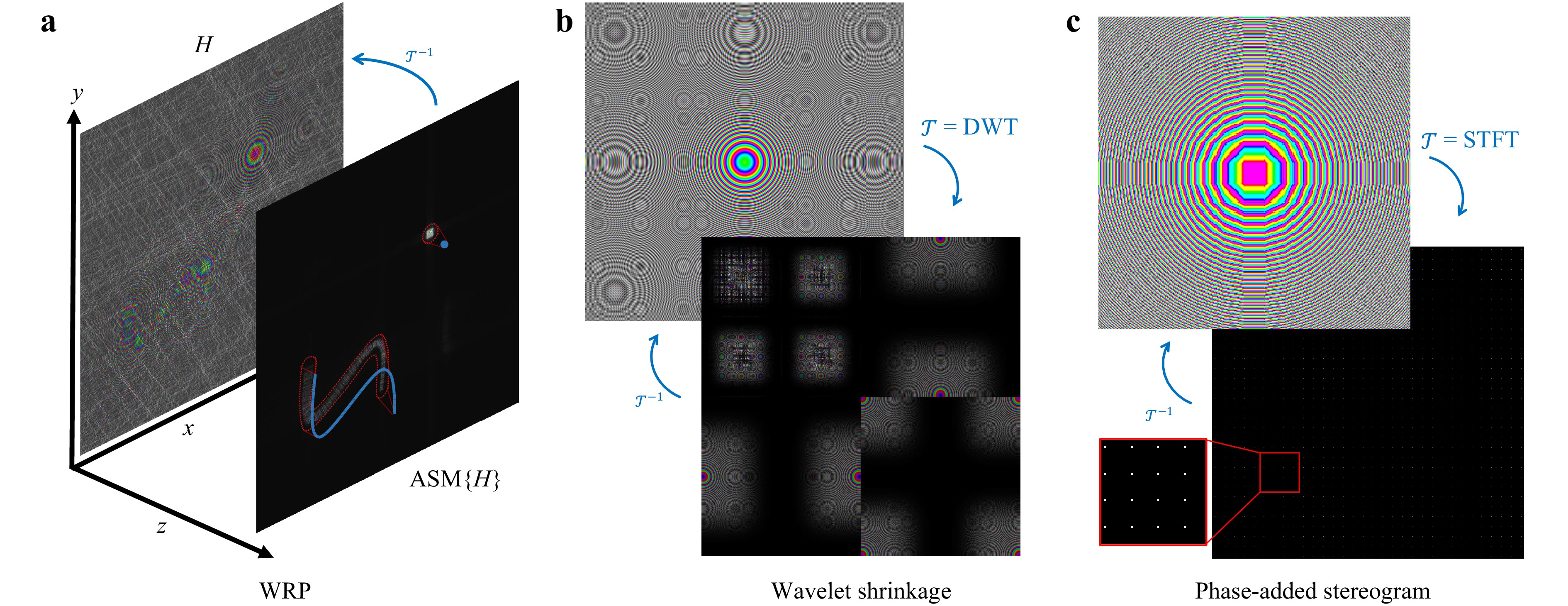
Fig. 6 Examples of sparse CGH methods. a The blue 3D curve and point are close to the WRP, only affecting nearby coefficients delineated in the red regions. This contrasts with the hologram plane H, where all pixels are affected. b A PSF and its corresponding sparse 2-level Daubechies-4 wavelet transform55. c Accurate PAS on 16 × 16 coefficient blocks with redundancy 2. Although the sparsity of 1/256 is high, it introduces noticeable distortions.
$$ 2\lvert d\rvert\tan({\theta}_{\max}) = 2\lvert d\rvert\tan\Big(\sin^{-1}\frac{\lambda}{2p}\Big) = \frac{2\lvert d\rvert\lambda}{\sqrt{4p^2-\lambda^2}} $$ (8) In the second case, the limiting angle can be found analogously.
Typically, WRP methods26,56 are point-based but that is not a necessary limitation as shown for example in36.
-
Holographic stereograms CGH are comprised of techniques which approximate generated holograms by mapping discretized light field coefficients into specific wavelet-like elements. Each element typically consists of small plane wave segments. The incidence of the ray position on the wavefield plane will determine the position of the centroid of the wavelet’s energy, while the incidence angle of the ray will determine the modulation frequency, according to the
$ \sin(\theta)=\lambda\nu $ relationship.These plane wave segments can be modeled in general by a short-time Fourier transform (STFT) for
$ {\cal{T}} $ . The STFT operator is defined as a family of apodized functions S with different combinations of translations$ (\tau,\upsilon) $ and frequency modulations$ (\omega,\eta) $ . Formally, we have$$ \begin{split}& {\rm{STFT}}\{H(x,y)\}(\tau,\upsilon,\omega,\eta) \equiv S(\tau,\upsilon,\omega,\eta)\\ &\quad= \iint_{-\infty}^{\infty} H(x,y) w(x-\tau, y-\upsilon) e^{-i (\omega x + \eta y)} \, dx \, dy \end{split} $$ (9) where w is a window function. Typically a rectangular function is used in stereogram CGH, but it can also be e.g. a Hamming or Gaussian window. For a given hologram, the family of functions S is sampled rectilinearly along all 4 dimensions depending on the hologram and scene properties.
The problem with the faithful conversion of rays to wave signals is the Heisenberg uncertainty principle: though a ray has an exact incidence position and angle, it is mathematically impossible for a signal to be simultaneously perfectly localized in space and frequency (i.e. diffraction angle). Thus there always will be an inherent approximation. By widening the window w, one can improve the frequency resolution but lower the spatial resolution, and vice versa.
The source of the emitted rays can be any number of scene elements covered in the previous sections, but they are most commonly point sources and discrete light fields. We can define a light field as being a 4D function
$ L(x,y,\theta_x,\theta_y) $ describing the light intensity of incoming rays at the hologram plane at coordinates$ (x,y) $ forming angles$ (\theta_x,\theta_y) $ w.r.t. the hologram normal (here the z-axis) along the x and y axes, respectively. This light field function is discretized, also sampled rectilinearly along its 4 dimensions. This yields a one-to-one correspondence between light field rays and STFT functions. The light field values can be obtained by rendering a scene with conventional computer graphics software, sampling the scene from multiple different virtual camera angles.The basic stereogram method is primarily concerned with amplitude values, either assigning random phase values57, or using structured phase patterns58. A major cause for quality loss is the lack of phase coherence across neighboring blocks: these will lead to frequent sudden jumps of the signal which degrades the overall quality of the reconstructions. This was first addressed in59 with the use of phase-added stereograms (PAS). By taking the distance a ray has traveled into account, one can modulate the phase as well to ensure coherence.
Originally, these stereograms were computed by subdividing the holograms into blocks and computing plane wave coefficients spatially. This was later accelerated and optimized by applying a block-wise FFT with compensated phase60. This is the special case where w is rectangular and the amount of STFT elements in S is exactly equal to the pixel count. This will cause the frequency space to be coarsely quantized. By increasing the sampling density along
$ (\omega,\eta) $ in S, we get the accurate phase added stereogram27, cf. Fig. 6c leading to more frequency coefficients per block, whose finer quantization substantially improves visual quality.There are also examples of non-rectangular window use in stereograms. In61, Hann windows are used for w, sacrificing some calculation performance due to the overlapping windows to get significantly better visual quality than most typical stereogram methods. Thanks to the overlapping windows, the space/frequency resolution trade-off poses less of a problem, making it nearly invariant to hogel size and scene geometry.
The advantage of stereograms is their high compatibility with conventional computer graphics software, allowing for the use of advanced rendering software to calculate all the ray intensities (and depths). Moreover, thanks to the high sparsity of needing to update only one coefficient per ray, and the efficient use of small FFTs, orders of magnitude speedups over conventional CGH can be obtained. The main drawback is the loss of quality. The stereogram approximation generally leads to apparent view discretization and loss of focal sharpness. Scene elements can also often only be placed in a constrained virtual 3D volume, leading to unacceptable visual quality losses otherwise.
-
Coefficient shrinking is more closely related to the traditional notion of sparsity in e.g. compression and denoising. A signal of interest is transformed with some candidate
$ {\cal{T}} $ , after which all coefficients below some threshold are set to zero. This threshold can be set to be some minimum energy, or to limit the maximum number of non-zero coefficients. For CGH, this principle can be applied on e.g. a point spread function, after which some predetermined fraction of the most significant coefficients are either precalculated and stored in a look-up table or computed on-the-fly.One of the first works calculating sparse CGH this way was done in62, leveraging Fourier domain sparsity. A point cloud is divided in clusters, where for each one high-magnitude PSFs coefficients are computed on a WRP. Then, the convolutional Fresnel diffraction in computed with the sparse FFT transform, which is faster than the regular FFT when the fraction of non-zero coefficients is small. A variant of this method was proposed by the same authors using precomputed coefficients as well63. Given the large contiguous zero regions in typical layer-based CGH, another sparse “SS-2DFFT” was also proposed64 to accelerate those CGH calculations.
Wavelets can also be used for
$ {\cal{T}} $ . In55, the WAvelet ShrinkAge-Based superpositIon (WASABI) method computes the significant Daubechies-4 wavelet coefficients for PSFs, with up to 30-fold speedups over the standard point cloud method (see Fig. 6b). By combining the wavelet transform with a convolutional diffraction operator, the algorithm is sped up further65. In later work, a similar shrinkage method was proposed using the the STFT instead, achieving a 2dB PSNR gain and better view preservation over wavelet-based methods66. This method was further improved and sped up by analytically computing coefficents rather than storing the precomputed values67.A major advantage of coefficient shrinking is the controllable sparsity, allowing for fine-grained control trading-off quality and calculation speed. But because wavefield signals have to be expressed directly in the transform domain, computing coefficients and the memory access patterns for making updates tend to be more complex.
-
Many diffraction patterns generated by 3D scene elements recur throughout the hologram. Instead of recomputing them each time, they can be computed in advance and stored in look-up tables (LUT)s which are optimized for fast memory access.
Most LUT CGH methods are designed for encoding PSFs. Precomputed wavefronts were already proposed in the first digital holographic display systems in the early 90's68, binning 3D points together into cells, each with a matching 1D wavefront for creating horizontal parallax CGH. Unfortunately, straightforwardly extending this principle to full-parallax CGH does not work, since storing 2D diffraction patterns for every possible 3D position would require far too much memory to be practical. Most of the research has thus focused on reducing LUT sizes by exploiting various symmetries.
The novel LUT method (N-LUT)28 only stores different axial realizations (along z) of PSFs, since we have translational symmetry in holography: moving a point laterally will accordingly shift the induced pattern by the same amount. This was later extended with the "run-length coding method", allowing for grouping points together in a single run when applying LUTs, leveraging scene symmetries since points tend to cluster together. The split LUT (S-LUT) and compressed LUT (C-LUT) techniques69,70 on the other hand utilize a separable representation of PSFs along the x and y axes, while the other methods71,72 leverage the PSF's radial symmetry by only storing the radial PSF function, and drawing out a whole PSF quadrant; the latter can then be duplicated and rotated by 90° repeatedly to obtain the complete PSF.
But LUTs are not only used to store PSFs. Precomputed patterns have been used for calculating line patterns73, or even surface elements with complex lighting patterns and occlusion masks37.
LUTs are very flexible, since in principle any values can be precomputed and stored for facilitating real-time CGH, representing objects of arbitrary complexity. A disadvantage in many cases is the limited number of encodable parameters, which otherwise leads to a combinatorial explosion of the LUT size in memory. LUTs are also not conducive to caching beyond a certain size, which can cause severe performance degradation; larger LUT may also not be suitable for FPGA or application-specific integrated circuit (ASIC) implementations.
-
When generating successive hologram frames in a holographic video display, one can not only leverage redundancies within each frame, but also leverage the temporal correlation between successive frames. The goal of dynamic CGH acceleration methods is to repurpose the data generated in prior frames to generate the current frame to lower the computational cost. This can be accomplished with motion compensation: given prior frame(s) and the known ground-truth motion of objects in the virtual scene, the frames can be transformed accordingly to match the scene composition in the current frame, which can be significantly less calculation-intensive than computing each frame from scratch. However, this compensation is never entirely accurate: even if the motion model is perfect, there is still some inherently missing information due to previously invisible object segments either entering the frame or becoming unoccluded by other objects.
An important complication with holographic motion compensation is the nature of diffraction itself. Unlike with conventional video, small object motion will alter all pixels of the hologram. That is why e.g. block-based motion compensation methods as found in modern video codecs fail for temporal decorrelation in holographic video compression3.
So far, only few attempts have been made to tackle this problem. In74–76, translational motion parallel to the hologram plane was compensated with the use of look-up tables storing wavefield segments. In77, 3D rotational motion was compensated using a formulation based on spherical holograms. General rigid body motion compensation was proposed for CGH in78, where new CGH frames were only recomputed when the compensation error surpassed some threshold. In the recent79, motion parallax was achieved in dynamic CGH compensation.
These approaches are unfortunately still limited: they can only compensate lateral translational motion parallel to the hologram plane, or only model global scene motion or rigid body motion of single objects. To be generally applicable, two main problems need to be addressed: (1) compensating arbitrary motion of multiple independently moving and mutually occluding objects; and (2) selective differential CGH rendering.
For (1), a first solution was proposed in80, by means of segmenting and masking holograms in Gabor space, together with global motion compensation operators. Mutually occluding objects with complex shapes and holes could successfully be compensated. For (2), general differential CGH methods are needed that only update the missing parts of the CGH signal to minimize computation costs. Because these differential signals are not directly expressible in the hologram plane efficiently, potential solutions may require transform-domain coefficient updates, similar to sparse CGH.
-
Deep learning is a class of machine-learning algorithms based on artificial neural networks. The "deep" adjective refers to the many concatenated neural network layers, allowing for learning and encoding highly sophisticated patterns. Deep learning has had a significant impact on many problems in the field of signal processing91.
In CGH, deep learning has been used as an accelerator or even substitute for different algorithmic components, cf. Fig. 7. Deep learning is particularly useful for complex non-linear optimization processes. It has been successfully used for optimizing the computation of phase-only holograms to minimize distortion w.r.t unapproximated complex-valued counterparts. This was first achieved for 2D scenes92, and soon after for more complex 3D scenes86,93,94, reporting significantly higher calculation performance over Gerchberg–Saxton95 and even Wirtinger holography96.
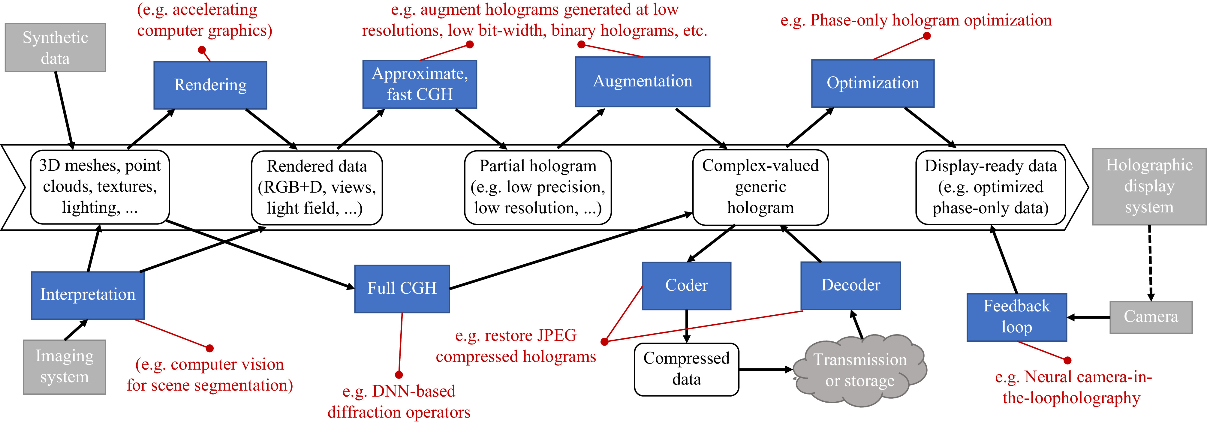
Fig. 7 Diagram of a general CGH pipeline and the utility of neural holography with several examples. Starting from captured or synthetic input data, the data is transformed in multiple phases, where DNN can improve, accelerate or even substitute algorithms. At the start, DNN can be leveraged for accelerating computer graphics rendering81 or computer vision82. DNN can augment data generated at low resolution83 or low bit-width84; replace diffraction operators85,86; compress holograms84,87; do speckle denoising88 and account for SLM limitations by optimizing phase-only hologram patterns89 or using DNN camera-in-loop holography90.
Deep learning has proven useful for extracting speckle-free views from generated holograms88, or for the creation of binary hologram patterns for DMD-based displays optimized to minimize the error with the ground-truth wavefield97. It has recently been used to optimize the output for phase-only holographic displays90, and even a full CGH pipeline based on deep learning was devised85 that can render realistic color holograms from RGB+depth input, especially suited for head-mounted holographic display systems with low power requirements.
Using deep learning has many benefits, flexibility of updating and tuning the neural network architecture and training algorithms, unparalleled optimization efficiencies, as well as optimized hardware systems (e.g. GPU) for both training and inference. A disadvantage of deep learning is its black box nature, i.e. it's hard to garner insights on how they work. It is also hard to guarantee whether a system can generalize to different or more complex 3D objects and non-homogeneous scene lighting, different display capabilities with e.g. larger viewing angles. Another open question is often also the robustness to outlier input data.
-
The main challenge for algorithmic accelerations is the streamlining of the data flow, such that neither a computational, memory, or bandwidth bottlenecks limits the rendering speed. Therefore, increasingly many methods are found that combine multiple acceleration methods such as LUTs and WRP sparsity35,36; WRPs and wavelets65; or stereograms, LUTs and WRPs98. In the end, the decision on which accelerations to choose for a given CGH algorithm always depends on the selected computing architecture (capabilities) and the desired visual effects. Nonetheless, the CGH algorithms in combination with the various accelerations techniques result in ranges of computational speed and it is unlikely that these will change in the foreseeable future, cf. Table 1.
-
Given the high requirements of high-end holographic video displays, purely algorithmic optimization with solely abstract complexity analysis are not enough. CGH algorithms need to be aware of the instructions and memory size and transport capabilities to reach optimality; furthermore, hardware can be tailored to the specific needs of CGH to increase power and computational efficiency. We will elaborate on many of these aspects in this section.
-
Since CGH is currently an active research field, most developments target consumer CPU and GPU hardware for system prototyping. A thorough overview of used hardware platform for CGH can be found in99. Since CGH requires the computation of millions up to multiple billions of pixels, and because the diffraction operator is linear, they lend themselves very well to massively parallel implementations and architectures. Examples of such implementations are the C++ “Computational wave optics library”41, the real-time color holographic display systems using a 12-GPU system100 and the open-source "HoloGen" CGH library101.
Because of the increasing complexity of modern hardware, proof-of-concept prototyping in e.g. MATLAB or Python may not suffice to ensure deployability for high-performance software implementations or competitiveness with existing solutions after optimization. One such aspect which has received little attention in CGH is caching: small data structures with predictable memory access patterns can be read an updated several orders of magnitude faster than large precomputed wavefront data. E.g. this can lead to the counter-intuitive result that on-the-fly calculation of PSFs can be faster than writing PSF LUT to the hologram plane.
An example of the importance of caching can be seen in102, where a straightforwardly optimized implementation on GPU of the “accurate PAS” CGH algorithm on GPU with a sparsity of about 0.1% only gives a speedup of 2.6 × over the reference point-cloud CGH, which has a far lower expected efficiency than the
$ \approx 1000 $ -fold reduction in coefficient calculations would indicate. By grouping coefficients together through the use of “lozenge cells”103, the memory access patterns are optimized leading to a speedup of 86.5 × over the reference with identical results to the base PAS version. -
In conventional displays high bit depths per pixel are important to faithfully represent colors, with modern displays having at least 8 bits per color channel. This is different for holography; the same property of diffraction, spreading the information content all over the hologram plane making CGH computation challenging, also makes holograms more robust to noise with limited visual quality loss. Since signal quantization is roughly equivalent to inserting uniform noise into a signal, holographic displays can still provide high visual quality with lower bit depths.
This principle was demonstrated in12,104, showing that under the right circumstances, 2-bit phase SLM displays will show only minor signal degradation compared to the 8-bit reference phase signal. That is why even binary holographic displays using DMDs can still be effectively used in high-quality holographic display systems105.
However, this property of holograms can therefore also be exploited for CGH: calculations can be made using lower precision representations, such as fixed-point integers or the half-precision floating-point format. The accumulated errors will mostly be concentrated in the least significant bits of the wavefield solution, which will have little to no visual impact.
The FFT is an instrumental algorithm in CGH, whose precision optimization would bring important benefits. To this end, an analysis of the fixed-Point accuracy of a low-precision FFT was made106, modeling the error propagation in for the purpose of CGH. A low-precision point-cloud CGH algorithm was proposed107 that computes Eq. 2 mostly using 1 byte per coefficients for intermediate computations. It relies i.a. on the fact that phase values encoded as fixed-point integers can safely overflow when represented as a multiple of
$ 2\pi $ . It utilizes GPU vector instructions and other intrinsics on packed integers, allowing for high throughput, gaining a 3-fold speed up over an optimized floating-point GPU implementation and a 15dB PSNR accuracy increase over a reference FPGA-based fixed-point integer solution. Low-precision optimizations are inherently used in field-programmable gate array (FPGA) due to the extensive use of fixed-point arithmetic, which is covered in the next section.Research on low-precision algorithms in the context of CGH is still relatively new, with much potential for further improvements as it is largely orthogonal to the other aforementioned algorithmic optimizations. For example, deep learning CGH solutions could in principle be optimized as well by reducing the representation precision and outputs of (some of) their layers.
-
A FPGA is a large-scale integration (LSI) that allows designers to freely rewrite logic circuits. An FPGA is composed of logic blocks (a look-up table that can configure any logic circuit), flip-flops, internal memories, switches between logic blocks, and input/output pins for external circuits. The designers can use a hardware description language to implement the desired circuit in the FPGA.
While recent CPUs and GPUs have operating frequencies on the order of GHz, FPGAs have operating frequencies on the order of several hundred MHz, thereby being an order of magnitude slower. However, if a large number of arithmetic circuits can be implemented in FPGAs and run in parallel, FPGAs can surpass CPUs and GPUs in terms of performance for specialized tasks. To maximize FPGA resource utilization, arithmetic circuits with small hardware footprints are required. CPUs and GPUs typically use floating-point operations, which require a lot of hardware resources. Contrarily, FPGAs can use fixed-point operations with small resource requirements. In addition, new hardware-oriented algorithms are required.
MIT Media Lab developed a media processor specialized for image processing called Cheops108,109 using FPGAs and digital signal processing LSIs. Cheops was capable of performing common image processing operations (matrix-vector multiplication, filtering, color space conversion, and so on) at a high speed. In109, Cheops was used as a CGH computational processor for holographic displays using acousto-optic modulators (AOMs). It was about 50 times faster than a workstation and about three to five times faster than a supercomputer (Connection Machine-2) during those days.
HORN (HOlographic ReconstructioN)110 is an FPGA-based computer series dedicated to CGH calculations. It is currently under development, up to its 8th model, and implements the point cloud algorithm on an FPGA, as defined in Eq. 3.
HORN-1110 and HORN-2111, which directly implement Eq. 3, were fabricated using discrete ICs and hand wiring, not using an FPGA. HORN-3112–119 and later versions were designed with FPGAs.
Fig. 8a presents a circuit designed to calculate Eq. 3 using adders, multipliers, and trigonometric look-up tables (LUTs). This circuit is designed by a pipeline circuit. The input data is
$ (x_j,y_j,z_j,a_j) $ , and the data are sequentially fed into the pipeline circuit. The data is processed and advanced to the next stage at every clock cycle. If the number of stages is$ N_s $ , the CGH calculation of the first input data is completed after$ N_s $ clock cycles. Thereafter, the object data after$ j \geq 2 $ is accumulated every clock cycle.
Fig. 8 CGH calculation circuits: a calculation pipeline for Eq. 3, b FFT-based diffraction calculation circuit.
In general, since
$ N \gg N_S $ , the computation of a single CGH pixel takes only about N clock cycles, which is a big advantage. Although there are techniques, such as software pipelining for CPUs and GPUs, the internal circuitry of CPUs and GPUs is difficult to fully pipeline. Let us assume that the computation of$ a_j \exp(\cdot) $ in Eq. 3 requires 20 floating-point operations. In this case, the CPU and GPU require$ 20 N $ clocks to compute Eq. 3. Contrarily, although the FPGA clock is an order of magnitude slower than the CPU and GPU, the FPGA is fully pipelined; thus, the computation takes only N cycles. This is sufficient to compensate for the difference in the operating frequency. In addition, since Eq. 3 can be computed independently for each pixel, the pipeline circuits can be prepared for each pixel to be computed in parallel.However, Eq. 3 requires a large number of multipliers. Since multipliers require more circuit resources than adders, it is desirable to minimize their usage. The recurrence formula method can calculate the phase of Eq. 3 using only additions113,114. The method developed by114 requires fewer additions than the method developed by113. By cascade-connecting the pipeline circuits that compute this recurrence formula, a large number of CGH computation circuits can be implemented. The latest HORN-8 has 4,500 CGH computation circuits mounted on an FPGA board, and by running them in parallel, the computation speed was six times faster than the latest GPU at the time.
An FPGA implementation with a modified data flow for the recurrence formula method has also been proposed120. Reference121 implemented the point cloud method in an application-specific integrated chipset (ASIC). The ASIC implementation did not use the recurrence formula method to simplify the design but instead used a pipeline circuit with Eq. 3. By arranging this pipeline circuit in two dimensions, 8 × 8 CGH pixels could be calculated in parallel. The ASIC was fabricated in 0.18 µm CMOS technology and operated at 200 MHz. Although the performance of the ASIC, which was several generations old, was not as high as that of FPGAs which use state-of-the-art semiconductor processes, it demonstrated the potential of ASICs for CGH computation.
Other than Eq. 3, sparsity-based CGH calculation67 has been implemented in an FPGA122. The light wave distribution of an object point on a CGH becomes sparse in the short-time Fourier transform (STFT) domain. Since the STFT requires multiple FFT operations, reference67 obtained an analytical solution in the STFT domain without FFT operations. A pipeline circuit to calculate this analytical solution was implemented in an FPGA122. The error and trigonometric functions included in this analytical solution were implemented in LUTs in the FPGA due to the large circuit size.
The polygon method has a good affinity with three-dimensional (3D) graphics, and CGHs can be calculated by calculating light propagation from polygons. Light waves from polygons are generally calculated using fast Fourier transforms (FFTs), but if the amplitude and phase of the polygons are constant, we can deduce an analytical solution. In123, the analytical solution of Fraunhofer diffraction from polygons was implemented in an FPGA. Since light waves from the polygons can be computed independently, parallelization of this computational circuit is expected to speed up the polygon method. However, this analytical solution has many calculations that are complicated and costly to compute (e.g., exponentiations, trigonometric functions, square root calculations, and divisions), which increase the required circuit area. It is difficult to install a large number of these calculation circuits.
Diffraction calculations are important in CGH calculations and are performed using FFTs. In124–126, the FFT-based diffraction calculation was implemented in an FPGA. Fig. 8b presents a schematic of the circuit. Since the two-dimensional (2D) FFT is separable, it can be computed by performing a row-wise 1D FFT followed by a column-wise one-dimensional (1D) FFT. In addition, since it is difficult to design a high-performance FFT circuit, FPGA vendors provide an intellectual property core (IP core) to calculate the FFT, and it can be used to design the circuit for diffraction calculation. FFT calculation results have a large dynamic range. CPUs and GPUs can use floating-point operations, so overflow is unlikely to occur, but FPGAs should use fixed-point operations to perform FFT where overflow must be considered. FFT IP cores usually have a scaling parameter to prevent such a problem. Novel solutions, including scaling information propagation and saturation, to further optimize efficiency and accuracy have been developed127. After computing the 2D FFT, the transfer function of Fresnel diffraction or angular spectral method is multiplied. The inverse FFT can then be computed using the same FFT circuit to obtain the diffraction results. In reference126, researchers were able to perform Fresnel diffraction of 512 × 512 pixels at 949 frames per second.
The layered method is a relatively simple way to generate high-quality CGH using RGB and depth images. In128, the layered method was implemented on FPGA. The layered method requires an iterative FFT-based diffraction calculation for the number of shades in the depth image. References124–126 were designed for digital holography, whereas reference128 was designed for the layered method. This circuit is also designed with fixed-point operations to reduce the circuit size. The units that perform the diffraction calculations are processed in parallel using 16 1D-FFT circuits. After the 1D FFTs are executed in the horizontal direction, the 1D FFTs are repeated in the vertical direction to calculate the 2D FFT. However, intermediate data created after the FFTs are executed in one direction cannot be stored in the FPGA memory; thus, it is stored in an external DRAM. This circuit was capable of computing full-HD CGH at 16 frames per second. Reference129 improved on this circuit by incorporating 32 FFT cores; it was capable of computing 4K-resolution CGHs at 30 frames per second.
To reduce speckle noise in holographic projections, there are two primary solutions: the error diffusion method and time averaging of CGHs computed at different random phases. Both methods will be explained later. References130 and131 implemented the computationally expensive error diffusion method and a speckle reducing method by time-averaging CGHs computed at different random phases on FPGAs, respectively. As in124–126,128,129, a 2D FFT is computed by repeatedly using 1D FFTs to generate a Fourier CGH. Six of these computation circuits are installed in one FPGA. The input images to this circuit are given different random phases, and six different CGHs can be obtained simultaneously. Although small FPGAs were used, the speedup was 2.5 times faster than a representative CPU of the time.
-
As mentioned in the introduction, a main key component of every holographic display is a spatial light modulator (SLM). In this section we are first going to discuss the few principal types of SLMs in existence, including their advantages and limitations before the remaining subsections explain in which ways DHs can be processed in order to achieve a better overall quality, before supplying them to a given SLM. In the last subsection, we are going to briefly summarize how visual quality of holographic displays can be assessed.
-
To compute CGHs, we propagate light virtually from a 3D scene to a hologram plane on which we obtain the complex-valued amplitude of the CGH; i.e. typically called complex(-valued) CGH. However, commonly available SLMs are either amplitude- or phase-modulated. These limitations will cause reductions in visual quality compared to a fully complex-valued modulation, as illustrated in Fig. 9. Furthermore, each SLM is classified into two types: those that can display grayscale CGHs and those that can only display binary CGHs. Liquid crystal displays (LCDs) are often used as SLMs that can display CGHs with a grayscale, whereas digital micromirror devices (DMDs) often can display only binary CGHs. The resolution of available SLM types is similar, but the switching speed of a DMD is about two orders of magnitude faster than that of LCDs, although it can only display binary CGHs.
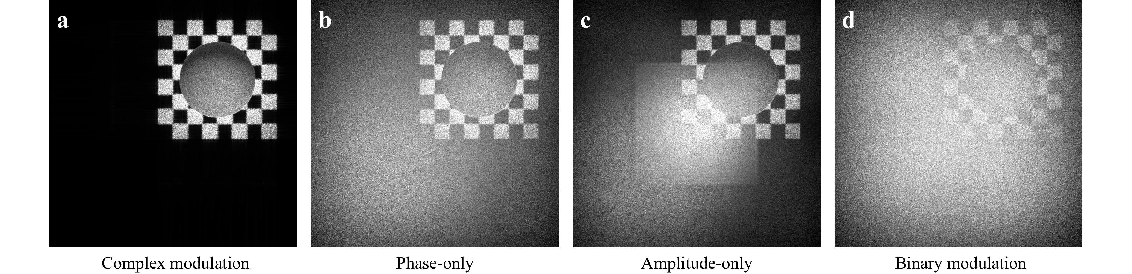
Fig. 9 “Sphere1A” hologram from the Interfere-III dataset51 in off-axis configuration with different modulation modes. Depending on the limitations of the SLM capabilities zeroth and conjugate orders or quantization noise may lead to visual quality degradation, for a fixed pixel pitch and pixel count.
We have to convert a complex CGH into an amplitude CGH or phase-only CGH (also called: “kinoform”). However, this causes loss of some of the original information of the complex-valued CGH, resulting in a degradation of the reconstructed image.
Complex CGHs can, in principle, produce almost perfectly reconstructed images. It is relatively easy to obtain a grayscale reconstructed image with amplitude CGHs, but zero-order and conjugate wavefields are visible in the reconstructed image, see Fig. 9c. Phase-only CGHs have the advantage that the zero-order wavefield can be avoided, see Fig. 9b. However, obtaining a grayscale reconstructed image is difficult with these CGHs due to the loss of amplitude information. In general, edges of a reconstructed image are emphasized in a phase-only CGH. This is because light diffuses widely and is widely distributed on the CGH when light hits the high-frequency components of the original image. On the other hand, the light hitting the low-frequency components of the original image does not diffuse light as much and is distributed in a part of the CGH. In phase-only CGH, the amplitude of the object light at the CGH is set to a constant. Because many CGH have signal properties resembling the frequency domain, this unit amplitude has a relative high-pass filtering effect, resulting in an edge-enhanced reconstructed image. Binary CGH also tends to produce an edge-enhanced reconstructed image for the same reason as phase-only CGH.
Random phase can be employed to better spread the object light information. This is often used in holographic displays with a wide viewing angle. The use of random phase can also reduce edge enhancement problems in the phase-only and binary CGHs described above. However, this will generated random interference on the reconstructed image, resulting in strong speckle noise. In the following sections, we discuss how to address these problems.
-
Although SLMs that can directly modulate complex amplitudes are not common, research has been conducted on achieving complex CGH modulation on SLMs. The main methods can be categorized into complex-amplitude encoding methods using one or two SLMs.
Reference132,133 proposed a method for displaying complex CGH using two SLMs. In reference133, two SLMs (an amplitude- and a phase-modulated SLM) are used to display a complex CGH. There are two formats for displaying complex CGHs, the polar format
$ u=A \exp(i \phi) $ , where A is the magnitude and ϕ is the argument of the complex amplitude, and the Cartesian format$ u=R+iI $ , where R and I denote the real and imaginary parts, respectively. This method uses the polar format. Namely, A is displayed on the amplitude-modulated SLM, and ϕ is displayed on the phase-modulated SLM. By optically projecting the phase distribution of the phase-modulated SLM onto the amplitude-modulated SLM using a relay optical system, the complex CGH can be displayed. The problem with the use of multiple SLMs is the alignment of the two SLMs at the pixel order (micrometer order) and the aberration caused by the lens and other factors134. On the other hand, the method using multiple SLMs can display higher-resolution complex CGHs compared with the method using a single SLM (described below).Many complex-amplitude encodings have been proposed that reconstruct complex amplitudes with only one SLM. In135, the display area of a single amplitude-modulated SLM is divided into two parts to display the complex CGH; this method uses the Cartesian form
$ u=R+iI $ . The real part, R, and the imaginary part, I, of the complex CGH are used as two amplitude CGHs, which are displayed in the divided SLM area. When a sinusoidal grating is placed on the Fourier plane of a 4f optical system, the two CGHs are optically transformed into a complex-amplitude CGH by spatially combining them on the output plane of the 4f optical system. Although the resolution of the complex CGH is halved, alignment is easier compared with the method developed by134, which uses two SLMs.The single sideband method with the half-zone plate method to obtain complex amplitudes using a single amplitude-modulated SLM has been proposed136,137. The amplitude CGH in this proposed method has, in principle, direct and conjugate light. The amplitude CGH is generated by superimposing real-valued point spread functions (PSFs), where the upper half of the PSF spectrum corresponds to the object light component and the lower half to the conjugate light component (or vice versa). If the lower half of the spectrum and the direct light component are removed in the Fourier plane of the 4f optical system, the complex amplitude of the object light can be obtained at the output of the 4f optical system. However, if half of the spectrum in the vertical direction is discarded, the vertical viewing area and the resolution of the reconstructed image are halved.
In recent years, the double-phase hologram138 has become a major method for reconstructing complex amplitudes in holographic displays using a phase-modulated SLM. This method is easy to understand by considering complex numbers as vectors. The complex CGH is represented as
$ u=A \exp(i \phi) $ , and its one pixel is represented as a vector. The double-phase hologram considers this vector as the sum of two vectors on the unit circle (the amplitude is always on the unit circle since the phase-modulated SLM cannot modulate the amplitude). Each vector is given by$$ \begin{split} &\exp(i(\phi+\cos^{-1}(A/2)) \\& \exp(i(\phi-\cos^{-1}(A/2)) \end{split} $$ (10) Note that A should be normalized. Although two phase-modulated SLMs are required Eq. (10), a multiplexing method can be used to synthesize complex CGHs using only one SLM139. The double-phase hologram can produce a reconstructed image with good quality, but the diffraction efficiency is low, resulting in a darker reconstructed image.
Binary amplitude encoding140 encodes the complex amplitude into a phase-modulated SLM by approximating the amplitude, A, of the object light in the CGH plane as a binary value using the error diffusion method. Here,
$ A \approx A_W + A_B $ , where$ A_W $ and$ A_B $ denote the on-pixel and off-pixel, respectively. In this way, the complex amplitude,$ A \exp(i \phi) $ , of the object light can be approximated as$$ A \exp(i \phi) \approx A_W \exp(i \phi)+A_B \exp(i \phi) \quad\quad $$ (11) $$ \quad\quad =\exp(i \phi A_W) + A_B \exp(i\phi). $$ (12) The second term is for the off-pixel (
$ A_B=0 $ ). Since phase-modulated SLMs cannot modulate the amplitude to zero, we generate a cancelling wave by alternating the phase of 0 rad and π rad to achieve$ A_B=0 $ . Binary amplitude encoding produces a brighter reconstructed image with almost the same quality as a double-phase hologram.We describe how to realize complex CGH using a binary SLM (DMD). Since a DMD can only control on/off pixels, it is more difficult to control both amplitude and phase compared with amplitude- and phase-modulated SLMs. The reference141 assigns a different phase to each pixel of the DMD. Each pixel in the DMD is grouped in a block (this block is called a superpixel, also known as a macro pixel). The complex amplitude is represented by the on/off sub-pixels in the superpixel. For example, if we consider a superpixel with 4 × 4 sub-pixels, we can represent 216 complex amplitudes. However, if the size of the superpixel is large, the number of pixels in the complex CGH becomes small. There is a tradeoff between the number of pixels and complex-amplitude accuracy. The reference142 improves over141 by augmenting it with an error diffusion method.
-
In CGH calculations, a random phase is added to widely diffuse the object light, but random interference occurs in the reconstructed image plane, resulting in speckle noise. In addition, when a complex-valued CGH is simply converted to phase-only or binary CGH, the amplitude information of the object light is lost, which may result in an edge-enhanced reconstructed image. This leads to image quality degradation. Noise reduction techniques used in digital holography and CGH are well summarized in143. In digital holography that capture holograms of real existing objects, sophisticated noise reduction algorithms, such as144, can be used on reconstructed images in a computer. In CGH, however, such algorithms cannot be applied to optically reconstructed images. In this section, we describe the following speckle noise reduction and image quality enhancement techniques for CGH: (1) Time-averaging methods, (2) Non-iterative methods and (3) Iterative methods. The complex-amplitude encoding introduced in the previous section is also effective for image quality enhancement.
-
Time-averaging methods reduce speckle noise by preparing multiple CGHs and reconstructing them in a time-averaged manner. In145, the speckle noise in the reconstructed image is time-averaged using an SLM that can rapidly switch CGHs generated with different random phases. The intensity of the reconstructed image of a CGH at time t is denoted by
$ I_{t} $ . By rapidly switching between CGHs with different random phase instantiations, the human eye can observe the time-averaged reconstruction$ I_{\rm{avg}}=\sum_{t}^{N} I_{t} $ where N is the number of CGHs. When N CGHs are time-averaged, the signal-to-noise ratio increases in proportion to$ \sqrt{N} $ . This is also known as one-step phase retrieval (OSPR)146. These methods are time-consuming because they require calculating many CGHs. In147, two SLMs can be prepared and one SLM can be switched in time to display N random phase patterns, and is illuminated with light to produce low-spatial coherence light. By irradiating the low-spatial coherence light to the other SLM (which displays the hologram), we can reduce the speckle noise in the reconstructed image. The SNR is improved proportionally to$ \sqrt{N} $ , as in145.In148, speckle noise was reduced by generating one random phase CGH, calculating N new CGHs by only changing the phase of this CGH by
$ \exp(2\pi i(n-1)/N), n\in\{1, ..., N\} $ and then performing a time-averaging reconstruction. Since this method requires computing only one CGH, it reduces the generation time of CGH compared with the method developed by145,146.A reconstructed pixel from a CGH is not infinitesimal but a spot of finite size. Pixel separation methods149–151 prepare object data thinned to a certain pixel spacing so that the spots with a finite size do not interfere with each other, generating a partition of multiple CGHs from this thinned object data (whereby the sum of this CGH data partition becomes the original object data). By the switching fast between these CGHs, an averaged reconstructed image with reduced speckle can be obtained since the adjacent pixels do not interfere. The averaged reconstructed image is expressed as
$ I_{pix}=\sum_{t}^{N} I_{t} $ where$ I_{t} $ denotes the reconstructed image of a CGH at time t. In recent work152, a light sculpting technique named "DCGH" was proposed modulating light both temporally and spatially at the same time. Because the optimization happens jointly in space and time, better speckle reduction for 3D holograms can be achieved rather than treating them separately. -
Speckle reduction techniques without iterative optimization have been proposed. The complex-amplitude encoding described earlier is one of the non-iterative methods. In this section, we discuss error diffusion methods, sampling grid methods, and random phase-free methods.
The error diffusion method reduces the quantization noise of an image by spreading it to the surrounding pixels. This method is often used in the image processing field (e.g., halftoning), but it has also been widely used in CGH for a long time130,153. When applying the error diffusion method to CGH, we first calculate the error
$ e(x,y)= u(x,y)-u'(x,y) $ between pixel$ u(x,y) $ in the original complex CGH and pixel$ u'(x,y) $ in the transformed CGH (amplitude, phase-only, or binary CGH). We multiply this error by certain weight coefficients and spread it to the surrounding pixels. For example, if we use the commonly implemented Floyd–Steinberg weight coefficient, we can perform the error diffusion method as follows:$$ u(x+1,y) \leftarrow u(x+1,y)+\omega_1 e(x,y) $$ (13) $$ u(x-1,y+1) \leftarrow u(x-1,y+1) +\omega_2 e(x,y) $$ (14) $$ u(x,y+1) \leftarrow u(x,y+1) +\omega_3 e(x,y) $$ (15) $$ u(x+1,y+1) \leftarrow u(x+1,y+1) +\omega_4 e(x,y), $$ (16) where
$ \omega_1=7/16 $ ,$ \omega_2=3/16 $ ,$ \omega_3=5/16 $ , and$ \omega_4=1/16 $ . By performing this operation on all the pixels, the error-diffused CGH (amplitude, phase-only, or binary CGH) is obtained. Raster scans are common, but serpentine scans have also been proposed154. Holograms that implement serpentine scans are also called bidirectional error diffusion (BERD) holograms, and they have been shown to improve image quality compared with raster scans. The weight coefficients can also be optimized using a genetic algorithm, but these weight coefficients are image-dependent155. In addition to the Floyd–Steinberg weight coefficients, many other weight coefficients have been proposed. In156, each weight coefficient and threshold method were comprehensively surveyed. The error diffusion method has also been used to improve the gray-level display characteristics of reconstructed images157,158. In CGH, the error diffusion method is widely used as a basic technique to obtain good-quality phase and binary CGH with low computational cost, but it darkens the reconstructed image.The sampling grid method multiplies the original object
$ o(x,y) $ by a sampling grid$ d(x,y) $ to reduce the edge enhancement problem of binary159 and phase-only160 CGHs. In160, the sampled object$ o_d(x,y) $ is expressed by$ o_d(x,y)=o(x,y) d(x,y) $ and we can obtain the final binary or phase-only CGH simply by propagating it to the CGH plane. This method does not require any prior information about the original object and CGH and is also computationally inexpensive. Binary and phase CGHs require that the amplitude of the object light in the CGH plane is uniform; however, the amplitude of the object light is usually not uniform. By adding random phase, the object light distribution can be made uniform, but strong speckle noise is generated. In the sampling grid method, sampling grids act as diffraction gratings and diffuse the object light, which helps make the amplitude of the object light on the CGH plane more uniform. This method uses a periodic sampling grid with 1s and 0s, resulting in a large number of voids. A method to obtain the optimal sampling grid with +1s and −1s using a stochastic binary search has been proposed161. Once the optimal sampling grid is obtained, it can be applied to other object images. The problem of many voids159,160 in the reconstructed image was solved by this method.In reference162, a tiled phase mask is obtained using an iterative optimization method introduced in the next section. In this method, a small phase mask with random phase is first optimized by iterative optimization. Then, the optimized small mask is tiled to the same size as the original image to obtain the final mask. The final mask is then multiplied by the original object, and a diffraction calculation is performed to obtain the CGH with low speckle.
A method to improve the image quality of CGH by applying a virtual spherical wave (quadratic phase) to the original object has also been proposed. The random phase-free method163,164 multiplies the original image by a virtual spherical wave
$ w(x,y)=\exp(i({\pi}/{\lambda f}) (x^2+y^2)) $ . The focal length f of the spherical wave is determined from the original object size$ S_o $ and the size of the CGH$ S_h $ as$ f=z/(1-S_h/S_o) $ where z is the distance between the CGH and the original object. The random phase-free method can produce a reconstructed image where the original image is larger than the size of the CGH without the use of random phases. Therefore, the random phase-free method can be used in lensless holographic projection. As another option, we can consider a random phase-free method that uses plane waves instead of spherical waves. Planar waves also have a smooth phase distribution, so speckle noise can be suppressed. However, when plane waves are used, only a reconstructed image of the same size as the hologram can be obtained, which cannot be used for lens-less holographic projection. Since the phase distribution of the reconstructed image is smooth, there is no unwanted interference between the reconstructed pixels, and the reconstructed image has a low speckle noise. When the random phase-free method is applied to the amplitude CGH, we can obtain a high-quality reconstructed image. However, when this method is applied to phase-only CGH, the complex amplitude of the CGH plane should be converted to the phase-only CGH using the error diffusion method to obtain a high-quality image164. As aforementioned, the error diffusion method results in a particularly dark reconstructed image; therefore, references165,166 use iterative optimization, described in the next section, to calculate the optimal spherical wave. This optimal spherical wave can be applied to an arbitrary original object, and the image quality of the reconstructed image can be improved. -
The Gerchberg–Saxton (GS) algorithm95,167 was developed for phase recovery problems in metrology. The GS algorithm uses known information in the spatial and Fourier domains as constraints and recovers the desired information via iteration using diffraction calculations. The GS algorithm is an iterative optimization method that is most commonly used in CGH. In optics, the lens-based GS algorithm is also called the iterative Fourier transform algorithm (IFTA) as lens-based light propagation can be simulated by FFT. Free-space propagation (Fresnel diffraction or the angular spectrum method) can also be used in CGH. It is intuitive that CGH can be optimized using the GS algorithm, but it was not well mathematically understood for some time. Later, it was found that the GS algorithm is a kind of nonconvex alternating projection algorithm. The history and theoretical background are detailed in168.
The optimization flow using the basic GS algorithm consists of the following steps.
1. Calculate the diffraction calculation from the object plane to the CGH plane.
2. Apply a constraint condition to the CGH plane (in the case of phase-only CGH, only the argument of the complex amplitude is taken. In the case of binary CGH, the complex amplitude is binarized).
3. Calculate diffraction from the CGH plane to the object plane.
4. Apply a constraint condition to the object plane (replace the amplitude component of the complex amplitude of the reconstructed image with the original object).
The starting point for optimization can be either the object plane or the CGH plane. Here, the object plane is used as the starting point. First, we set the original object with an appropriate phase (random phase is often used). We calculate the complex amplitude in the CGH plane by performing diffraction calculations. If the final desired CGH is an amplitude, phase, or binary CGH, we convert the complex amplitude by taking the real part, calculating the argument, or converting to binary, respectively. This transformation is the constraint on the CGH plane. Then, the inverse diffraction calculation is performed to obtain the reconstructed image. In the object plane, the phase of the reconstructed image is used as a free parameter, and the amplitude of the reconstructed image is replaced by the original object. By iterating this process, the desired CGH can be gradually obtained. An extension of the GS algorithm to 3D objects has also been performed169,170. For 3D objects, the GS algorithm can be applied to each layer with different depths, similar to the layer method169. Alternatively, we can record the complex amplitude of the 3D object in any plane and use that complex amplitude as the object plane constraint170 (similar to the double-constraint GS method described below). Increasing the free parameters makes the optimization easier. The Fidoc algorithm171 provides a free parameter area outside the original object (this area is also called the noise area).
Although the GS algorithm is easy to implement, it is prone to local minimum solutions. An approach to solve this problem is introducing weighted feedback. The weighted GS algorithm in172 uses weights calculated by
$ w^{(k)}(x,y)=\exp(A_o(x,y)-A_r^{(k)}(x,y)) $ , where$ A_o $ is the amplitude of the original object and$ A_r $ is the amplitude of the reconstructed image. This method prepares a noise area171 and imposes the following amplitude constraints on the object area (S) and noise area ($ (x,y) \notin S $ ) as object plane constraints.$$ {A^{(k + 1)}}(x,y) = \left\{ {\begin{array}{*{20}{l}} {{w^{(k)}}(x,y){A_o}(x,y)}&{(x,y) \in S}\\ {{A_r}(x,y)}&{(x,y) \notin S} \end{array}} \right. $$ (17) where k denotes the index of iterations. In this method, the quadratic phase163–166 is introduced to the initial phase of the object plane to facilitate optimization. In the other weighted GS algorithm of173, a noise area was prepared171, and the following amplitude constraints on the object region (S) and noise area as object plane constraints were imposed.
$$ {A^{(k + 1)}} = \left\{ {\begin{array}{*{20}{l}} {{A^{(k)}}(x,y){{({A_o}(x,y)/{{A'}^{(k)}}(x,y))}^{{\beta _k}}}}&{(x,y) \in S}\\ {{{A'}^{(k)}}(x,y)}&{(x,y) \notin S} \end{array}} \right. $$ (18) where
$ A^{(k)}(x,y) $ denotes the amplitude of the previous optimized object plane,$ A_{o}(x,y) $ denotes the amplitude of the original object,$ A'^{(k)}(x,y) $ denotes the reconstructed amplitude from the CGH, and$ \beta_k=\sqrt{\beta_{k-1}} $ denotes the adaptive parameter.The GS algorithms described above use only the amplitude information of the original object as the object plane constraint. The double-constraint GS algorithm174 uses both the amplitude and phase of the original object as constraints in the object plane. Since this eliminates the free parameter region, a noise area171 is introduced around the original object. This method can be thought of as complex-amplitude encoding using the GS algorithm.
The GS method can be used for binary CGH optimization, but a direct binary search175 is also often used. In this method, each pixel of a binary hologram is inverted. If the quality of the reconstructed image is improved by the inversion, the inverted pixel is adopted; otherwise, the original pixel is used. This is done for all the binary pixels and is one iteration. By repeating this iteration, we can obtain a binary CGH that improves the quality of the reconstructed image. Direct binary search requires a large number of diffraction calculations and thus takes a long time to optimize. The stochastic direct binary search176 speeds up convergence by probabilistically inverting each pixel. The original binary direct search175 speeds up the computation by adding and subtracting the analytical solution for a single pixel change, without diffraction calculations. A similar idea was proposed to speed up the computation by storing the result of the diffraction calculation for a single pixel in a LUT and then adding and subtracting the data in the LUT according to the inverted pixel from the reconstructed image177. The direct binary search is also prone to local minimum solutions. To get rid of the local minimum, simulated annealing is employed, which is a method that probabilistically changes the adoption of inverted pixels. Simulated annealing is a heuristic optimization method that has been used to optimize phase-only CGH178.
The gradient descent method iteratively optimizes the CGH using the gradient of a differentiable loss function
$ {\cal{L}} $ (also called the objective function). A basic gradient descent method is expressed as$$ u \leftarrow u - \alpha \frac{\partial{{\cal{L}}}}{\partial{u}} $$ (19) where u represents a CGH or object to be optimized; α denotes a learning parameter;
$ \leftarrow $ means an operator that updates the calculated value on the right side to the variable on the left side. The choice of loss function is arbitrary, but those most commonly used are mean squared error (MSE) and total variation.Wirtinger holography96, which applies the gradient descent method with complex derivatives to CGH, has succeeded in obtaining better image quality than the GS algorithm and double-phase hologram. Wirtinger holography minimize the error
$ {\cal{L}}=||{\cal{P}}(\phi)|^2-I| $ using the gradient descent method of Eq. (19), where$ {\cal{P}}\{ \cdot \} $ denotes a diffraction calculation, e.g. we can use Eq. 5 as the diffraction calculation; ϕ is the phase-only hologram; I is the ground truth target image. The loss function involves complex value operations, but fortunately, current deep learning frameworks179,180 can easily handle such complex derivatives.In181, the optimization of a phase CGH generated by the layered method is performed using the gradient descent method. Since it is difficult to perform optimization for each layer of a 3D scene, the complex amplitude of the 3D scene is recorded on a virtual plane, and this is the ground truth, O. The loss function is defined as
$$ \begin{split}& {\cal{L_{M}}}(\Re\{O\},\Re\{{\cal{P}}(H)\})+{{{\cal L}_{M}}}(\Im\{O\},\Im\{{\cal{P}}(H)\})+ \\ &\beta {{{\cal L}_{M}}}(|O|_{b},|{\cal{P}}(H))|_b), \end{split} $$ (20) where O is the complex amplitude of the 3D scene; H is the CGH to be optimized;
$ {{{\cal L}_{M}}}(a,b) $ is the MSE of a and b;$ \Re $ and$ \Im $ are operators that take real and imaginary parts, respectively;$ |\cdot|_b $ is the background region of the argument; and β is a parameter that represents the importance of the background region and is an empirically determined hyperparameter. All operations in this loss function are differentiable. By differentiating the loss function with respect to H, the minimum loss with respect to O (i.e., the optimal H) is obtained using the gradient descent method. The gradient descent method is time-consuming as it requires iterative optimization, but it produces reconstructed images with better quality than the double-phase hologram. -
The GS algorithm and Wirtinger holography described above work well for ideal optical systems. However, in real optical systems there are aberrations and SLM nonlinearities. Without correcting for these, it is not possible to obtain the desired accurate reconstructed image. Some techniques have been proposed for manually correcting these aberrations, but they require a lot of work for every new setup configuration. Recently, camera-in-the-loop-holography has been proposed to solve this problem85,182,183. In camera-in-the-loop-holography, optical aberrations and aberration-corrected CGHs can be obtained by minimizing the error
$ {\cal{L}} $ between the actual reconstructed image captured by a camera and the ground-truth image using the gradient descent method of Eq. 19. The study182 constructed a DNN that can infer the aberrations of a real optical system. This DNN is trained using a dataset of numerically reconstructed images from CGHs and optically reconstructed images captured by a camera (including aberrations of the optical system).The camera-in-the-loop-holography of85 optimizes the CGH ϕ so that the aberrations are corrected using gradient descent Eq. 19. The gradient descent method performs the following iterations:
$ \phi \leftarrow \phi - \alpha ({\partial {\cal{L}}}/{\partial \phi}) $ , where$ {\cal{L}} $ is the error between the actual reconstructed image captured by a camera and the ground-truth image. The gradient$ {\partial {\cal{L}}}/{\partial \phi} $ can be expressed as$$ \frac{\partial {\cal{L}}}{\partial {\phi}}=\frac{\partial {\cal{L}}}{\partial {\cal{P}}'} \frac{\partial {\cal{P}}'}{\partial \phi} $$ (21) where
$ {\cal{P}}' $ represents the actual light propagation in the optical system including aberrations. Since this light propagation operation is unknown,$ {\partial {\cal{P}}'}/{\partial \phi} $ cannot be calculated directly. By approximating$ {\cal{P}}' $ with$ {\cal{P}} $ , the light propagation of the ideal optical system in Eq. 5,$ {\partial {\cal{L}}}/{\partial\phi} $ can be calculated as$$ \frac{\partial {\cal{L}}}{\partial {\phi}} \approx \frac{\partial {\cal{L}}}{\partial {\cal{P}}'}\frac{\partial {\cal{P}}}{\partial \phi} $$ (22) Using this gradient, we can optimize the CGH. This method is unique in that it does not require prior calibration of aberrations in the optical system, nonlinearities of the SLM, alignment errors, etc.; and these are automatically corrected while optimizing the CGH. Since this method requires re-running this optimization calculation for each image, the study85 showed that by training a DNN with camera-in-the-loop-holography, an optimized CGH can be inferred from the DNN quickly.
In90, a neural network is trained by camera-in-the-loop holography, and after training, it can output CGHs for any 3D scene. While this training takes a long time, the inference is very quick. Reference183 incorporates two SLMs into a Michelson interferometer to reduce undiffracted light generated by the SLMs by interference. This method is capable of obtaining a high-quality reconstructed image. The CGH that is displayed on each SLM is
$ H_1, H_2 $ . If the image reconstructed (optically captured) by the Michelson interferometer is R, the loss function can be expressed as$ {\cal{L}}={{{\cal L}_{M}}}(R, O) $ . From the gradient descent method, we iteratively optimize$ H_1, H_2 $ using the following equation:$$ H_1 \leftarrow H_1-\alpha \partial {\cal{L}}/ \partial H_1 $$ (23) $$ H_2 \leftarrow H_2-\alpha \partial {\cal{L}}/ \partial H_2. $$ (24) This method produced reconstructed images with better quality than double-phase holograms, Wirtinger holography, and camera-in-the-loop holography using a single SLM.
-
Visual quality assessment (VQA) plays a key role for any signal processing pipeline that drives a display system. This is true for any display setups, but especially for comparing developing display prototypes and parametrizing algorithms. The perceived quality of a visualized CGH-DH is determined by a combination of the scenes render quality, as well as the preservation of its various 3D focal cues. All of which can be impaired for many reasons in a holographic display.
A reduced quality can be due to the chosen CGH method, namely its capabilities, approximations, or its parametrization. Examples are: a reduced range of supported visual effects (e.g. no shadows, no specular lighting), the use of computational accelerations (e.g. LUTs, coarse occlusion masks, approximations to the diffraction integral) and e.g. a limited render-primitive count or erroneous/low resolution 3D input data.
Visual quality may also be impaired due to further steps of the holographic signal processing pipeline3, such as lossy compression, hologram tiling, or modulation-narrowing transforms to match the supported screen capabilities (e.g. phase-only SLMs, binary SLMs, 8 bit dynamic range 2D displays).
Finally, optical components of the display setup may further impair quality — such as through: low contrast and/or limited spatial-resolution SLMs, reference wavefront errors, optical aberrations, alignment errors.
Whenever all components should be taken into consideration, only subjective assessment by human observers is a viable strategy. However, upon the development of each individual component, typically non-visual, targeted objective quality assessment is predominantly used due to its fast and automated evaluation.
-
For subjective VQA of DHs various distorted and ground-truth reconstructions are presented to several dozens of human observers. Each of them is asked to grade the quality for which various schemes exist, see e.g.184. The subsequently formed mean opinion scores serve as the ultimate ground-truth of visual quality. The assembly of a test dataset that results in meaningful scores requires a lot of experience.It can even be impossible as in the case where visual defects are not very comparable. For example, information missing in a reconstruction versus a blurred version of the entire scene. Another hindrance for subjective tests, esp. on DH display setups, can be hardware limitations184 that do not allow for visualizing the complete content. These limitations can be for example a too narrow angular field-of-view, limited reconstruction size, limited depth-refocusability, or low contrast. Subjective tests always involve a lot of administrative and organizational overhead and easily take several weeks to months to complete. To ensure for some degree of reproduciblity, they require well-defined testing procedures and monitoring the visual conditions of the test subjects (e.g. test for visual acuity) and the test environment (e.g. ambient light intensity, ambient light color temperature, observer distance). In short, subjective tests are a heavy-weight, accurate tool and most importantly they cannot be utilized for real-time monitoring purposes.
-
Objective quality assessment of DHs entails the evaluation of mathematical functions on the numerical reconstructions or wavefields. These functions are called objective quality metrics, should have a known relation to the perceived visual quality of the reconstructed DH. They may be reference-based or reference-free. No-reference objective quality metrics require an advanced knowledge of the assessed data statistics and properties and therefore much harder to develop. For VQA of DHs, almost exclusively full reference-based metrics are used, which require some sort of ground-truth to compare to. Examples of some of widely used image quality metrics, borrowed from 2D image VQA, are the peak signal-to-noise ratio (PSNR) and structural similarity index measure (SSIM)185. The great advantages of objective measures are reproducibility across different setups and the small effort of evaluation allowing for fast quality monitoring. The disadvantages are that they: necessarily require a ground-truth, can be internally limited in dynamic range, and are only an approximation to the subjectively perceived quality. Nonetheless, developing efficient objective measures to specifically cope with complexities of evaluating DH and to provide exclusive assessment of DH 3D aspects is greatly sought after and currently an open topic in the field.
-
Some properties of DHs cause additional complexities and prevent simple re-use of QA strategies as used for videos and images. One problem that both VQA strategies share for any plenoptic content, including DHs, is that some form of score pooling is required for the different viewpoints (gaze angles and focal distances). One and the same hologram may appear heavily distorted only at certain viewpoints and the importance of all supported viewpoints has to be weighted. The pooling allows for example to prioritize good quality center view reconstructions over reconstructions from large viewing angles or vice versa. For DHs the pooling strategy is currently often chosen as a simple arithmetic mean. Over time best practices will be established likely for all plenoptic imaging techniques, as this problem is also studied for point cloud imaging/volumetric displays186–189 and lightfields190,191).
Aside from practical limitations such as limited compute capabilities or difficulties arising from multi-terabyte-sized test datasets, there are several problems specific to DH. Publicly available data sets including both optically recorded and CGH holograms from various 3D models/real objects with diverse scene-composition and object characteristics are currently scarce. Only few of such public data sets have been created in recent years37,38,54,192–195.
True optical holographic display setups are currently limited in their maximal resolutions and screen sizes supported by modern spatial light modulators. In addition, only few labs combine the required expertise of optical engineering and VQA. Therefore, frequently numerical reconstructions are displayed during subjective VQA on alternative display types, such as conventional 2D displays and light field displays; see for example Fig. 10. Fortunately, the test sensitivity of 2D displays seems to be the highest at least for compression artefacts as found in a first study184.

Fig. 10 Comparison of display setups used for subjective VQA of DHs. Approximate screen diagonals are 30 cm, 200 cm, and 5 cm, respectively. Reprinted with permission from184 © The Optical Society.
Because holography is a coherent imaging technique it suffers from a multiplicative, uncorrelated speckle noise, similar to radar196 and ultrasound imaging197. Speckle noise is a problem for subjective VQA and even more for element-wise applied objective VQA198,199. The noise is less visible and comparatively easy to suppress in optical setups by trading off some resolution, e.g. through the use of partially coherent illumination in the display setup. In numerical reconstructions however, speckle denoising has to be performed per viewpoint and incurs a large computational cost. An excellent review of optical and algorithmic speckle denoising techniques is provided in143. Speckle denoising methods were evaluated in the context of metrological applications in e.g.200, and for visualization of macroscopic scenes in199,201,202.
Since currently numerical reconstructions are a major tool for both VQA tracks, their calculation in large numbers becomes a problem, as it is extremely costly for high-resolution color DHs. It can take CPU-weeks for large databases when evaluating multiple test combinations.
To avoid the need for pooling and the need for interim reconstructions, objective metrics have also been studied in direct application to wavefields. As most metrics expect a given dynamic range, non-negative content, or real-valued inputs their direct application to DHs is however not evident either. Nonetheless, correlations with subjective quality scores were investigated in198,203,204 but no general metric has emerged as a reliable choice yet and more research is needed.
The most notable progress in the past years on the VQA of non-metrological applications can be mainly attributed to the JPEG Pleno Holography205 standardization effort on the development of novel DH compression schemes. It has already lead to several publications and a first consensus of several leading research groups on a first subjective184,199,206 and objective198,199,207 evaluation pipeline.
-
Although VQA has a high importance for macroscopic display applications, there exists only early research results which are limited to the preliminary assessment of compression artifacts and denoising applications. More complex problems associated to VQA of binary and colour holograms as well as dynamic holography, are almost completely untouched till now208. Therefore, significant additional research is needed for the advancement of holographic signal processing pipelines3, including CGH methods.
-
Tremendous advances in CGH algorithms in terms of both visual quality/photorealism and computational complexity have been made, especially in recent years. Multiple classes of CGH techniques have been developed with different trade-offs, which should be chosen depending on the needs of the holographic display system's application. Given the high computational requirements of holography, care was taken to optimize many aspects of CGH, starting from approximating the laws of diffraction, compact mathematical representation of graphical basis elements, algorithm design with acceleration structures tailored to modern computing hardware, optimizing for the display capability limitations of SLM devices and even hardware software co-design with dedicated ASIC for CGH.
Despite all these optimizations, the computation of high-resolution, wide viewing angle photo-realistic DHs in real-time remains an important challenge to be tackled. Nevertheless, existing real-time CGH implementations show that driving high quality holographic displays is already feasible and ahead of current displaying hardware resolutions.
In the near term, we expect head-mounted-display type fully diffractive displays to be the first commercially available holographic display systems given their relatively lower technical requirements, likely before the end of the decade. Current CGH algorithms can already drive these display types in real-time, but doing so at high visual quality and with low energy consumption is still an active domain of research. Large full-parallax holographic display systems with high SBP will probably take longer to be widely available due to their much higher computational and display requirements.
In the future, we believe that the further close integration of CGH algorithms with dedicated hardware systems will likely yield the biggest computational gains, enabling immersive holographic television.
-
This research was funded by the Research Foundation - Flanders (FWO), Junior postdoctoral fellowship (12ZQ220N), the joint JSPS-FWO scientific cooperation program (VS07820N) and the Japan Society for the Promotion of Science (19H04132 and JPJSBP120202302). We would like to thank Ayyoub Ahar for advising us on visual quality assessment.
The state-of-the-art in computer generated holography for 3D display
- Light: Advanced Manufacturing 3, Article number: (2022)
- Received: 16 September 2021
- Revised: 28 April 2022
- Accepted: 07 May 2022 Published online: 10 June 2022
doi: https://doi.org/10.37188/lam.2022.035
Abstract: Holographic displays have the promise to be the ultimate 3D display technology, able to account for all visual cues. Recent advances in photonics and electronics gave rise to high-resolution holographic display prototypes, indicating that they may become widely available in the near future. One major challenge in driving those display systems is computational: computer generated holography (CGH) consists of numerically simulating diffraction, which is very computationally intensive. Our goal in this paper is to give a broad overview of the state-of-the-art in CGH. We make a classification of modern CGH algorithms, we describe different algorithmic CGH acceleration techniques, discuss the latest dedicated hardware solutions and indicate how to evaluate the perceptual quality of CGH. We summarize our findings, discuss remaining challenges and make projections on the future of CGH.
Research Summary
The state-of-the-art in computer generated holography for 3D display
Holographic displays have the promise to be the ultimate 3D display technology, able to account for all visual cues. Recent advances in photonics and electronics gave rise to high-resolution holographic display prototypes. There is a major computational challenge in driving those display: computer generated holography (CGH) consists of numerically simulating diffraction, which is very computationally intensive. David Blinder from Belgium’s Vrije Universiteit Brussel and IMEC, Tomoyoshi Shimobaba from Japan’s Chiba University and colleagues give a broad overview of the state-of-the-art in CGH. This includes a classification of modern CGH algorithms, describing different algorithmic CGH acceleration techniques, covering the latest dedicated hardware solutions and how to evaluate the perceptual quality of CGH. The remaining challenges, projections on the future of CGH and its potential for photorealistic 3D display are discussed.


Rights and permissions
Open Access This article is licensed under a Creative Commons Attribution 4.0 International License, which permits use, sharing, adaptation, distribution and reproduction in any medium or format, as long as you give appropriate credit to the original author(s) and the source, provide a link to the Creative Commons license, and indicate if changes were made. The images or other third party material in this article are included in the article′s Creative Commons license, unless indicated otherwise in a credit line to the material. If material is not included in the article′s Creative Commons license and your intended use is not permitted by statutory regulation or exceeds the permitted use, you will need to obtain permission directly from the copyright holder. To view a copy of this license, visit http://creativecommons.org/licenses/by/4.0/.

 DownLoad: