


-
Neuroscience nowadays routinely utilises optogenetic toolsets to stimulate and silence functional activity within neuronal networks and even individual neurons in-vivo1-5. The efficient application of modern optogenetics relies on precise spatial-temporal control of light. Achieving this non-invasively is, however, challenging when targeting deeply-located brain regions, since tissue scattering prevents sufficient localisation (focusing) of optical power. Separately, invasive solutions often cause high risks of tissue damage, growing with tissue depth. Optical fibres are commonly seen as a solution for minimally-invasive light delivery, enabling stimulation and activity recording in deep brain regions due to their miniature footprint6−8. Advanced fibre probes, such as multi-channel probes9, fibre bundle10 or tapered fibre11,12 have been developed for targeting multiple regions.
Recently, holographic endoscopes, relying on imaging through hair-thin multimode fibres, were successfully demonstrated in in-vivo deep-brain imaging achieving cellular and even subcellular resolution13−15. An ongoing challenge for holographic endoscopy in freely moving animals, which has attracted significant attention of the relevant research community16−19, remains to maintain the highest imaging performance while the fibre undergoes bending deformations. Amongst the multitude of competing strategies, possible solutions were proposed by exploitation of complex numerical and machine-learning algorithms20,21, exploitation of guide-stars22,23 and bending resilient fibres24,25.
In this work, we designed and manufactured a hybrid, multimode – multicore fibre (M3CF), which features 61 corelets spaced with
$ \approx4\times $ the density of neurons in typical brain tissue (see Fig. 1a for the description of its anatomy). Thanks to the cascaded refractive index in its structure, the fibre allows two regimes of light transport resembling either a multimode fibre or a fibre bundle, with the possibility to switch from one regime to another by controlling the numerical aperture (NA) of the light coupled into the structure. The multimode fibre regime is to be exploited in the initial phase of an in-vivo experiment in order to navigate the distal end of the endoscope towards the desired brain structure and map out the layout and the connectivity of the neurons in the circuits under investigation. Following the implantation, anchoring the distal end with respect to the desired neuronal circuit and mapping out the connectivity context (all to be performed in immobilised models under anaesthesia), the fibre-bundle regime is to ensure light transport to and from each individual neuron in the field of view despite the motion of the awaken and behaving animal model. The proposed application scenario, therefore, consists of two parts - acute high-resolution imaging session (multimode regime) for guided implantation in sedated animal and later chronic studies in the motile model utilising low-resolution (bundle regime) stimulation and readout of preselected areas of interest.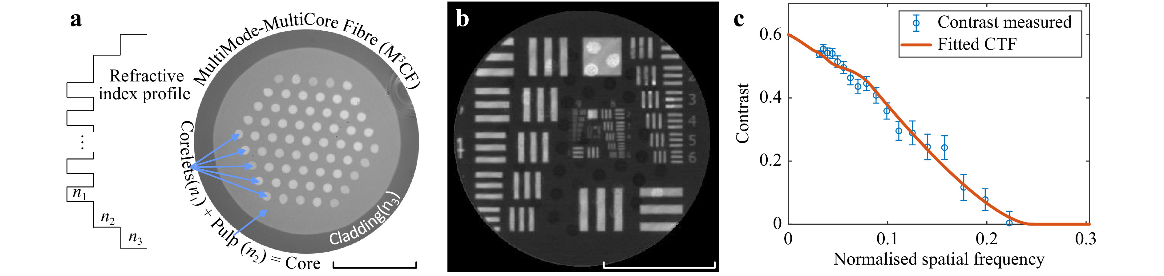
Fig. 1 Probe design and optical resolution assessment. a Microscope image of the cross-section of the manufactured M3CF. b Image of a negative USAF 1951 target acquired through the M3CF by the means of holographic endoscopy. c Image contrast as a function of normalised spatial frequency and the fitted transfer function (CTF) corresponding to an aberration-free imaging system with a circular aperture. Scale bars indicate a length of 100 µm.
To verify the desired qualities of the manufactured M3CF waveguide, it was utilised in a testing holographic endoscopy system, which has been optimised to provide control over the light transport in both regimes. While kept in stationary configuration, the best achievable resolution of imaging, based on raster-scanning a diffraction-limited focus, has been estimated. Further, the M3CF has been subjected to a series of tests under which the impact of fibre bending on the imaging (multimode fibre regime) and targeted light delivery (fibre bundle regime) has been assessed.
-
The M3CF, presented in Fig. 1a, was developed using the stack and draw technique, as described in the Methods section. The cladding and the pulp, with diameters of 278 µm and 232 µm respectively, form a step-index multimode waveguide with a refractive index difference corresponding to an NA of 0.1. The corelets with a diameter of 11.3 µm are equidistantly distributed across the core with a spacing of 9.8 µm. Size-wise, the design is balanced around two aspects - respecting morphological features of the neuron cell structures to be imaged and minimising cross-talk between the corelets and the pulp. Particularly, the core size and inter-core separation are comparable to the typical rodents neuron cell body, making it rather unlikely to have no overlap between cores and underlaying cell bodies during the experiment. An increased refractive index of the corelets, with respect to the surrounding material of the core, denoted in this paper as ‘the pulp’, is tailored to form an additional step in the index profile, resulting in an NA of 0.1. The cascaded index profile plays a key role in the presented design, enabling the core and the corelets to be addressed independently by changing the coupling NA.
-
Light coupled into the area of the corelets under NA below 0.1 will remain confined in the corelets. In contrast, signals falling into the NA interval of 0.1 and 0.2 would cross the index barriers between corelets and the pulp, which on its own only supports light transport below the 0.1 NA threshold. Although individually indexes of the corelets and pulp correspond to 0.1 NA only, light propagating in the pulp causes an imaging resolution enhancement in the corelets region as shown in previous studies26,27.
Therefore, when implemented in the wavefront shaping system, light propagation is supported across the whole core, and despite leading to different resolution across the pulp and the corelets’ areas, it enables high-contrast imaging across the entire core area. The wavefront shaping technique relying on an acquisition of the fibre transmission matrix28−31 is utilised in this work, allowing the formation of focal points at desired positions across the chosen focal plane behind the distal fibre facet. A sequential illumination of the negative USAF 1951 test target with accordingly generated foci while collecting light passing through, allowed the assessment of the resolution of the system as presented in Fig. 1b. Visibly non-uniform intensity across the fibre facet is likely due to higher wavefront shaping fidelity achieved at corelets regions. Featuring remarkable circular symmetry, the latter can preserve a circular polarisation state of the propagating light20, allowing for generating high-contrast focal points, while controlling only a single polarisation state at the input side of the fibre as performed in our study. Note that in our assessment, we subject the complete recorded image to the analysis, deliberately making ourselves blind to whether the local response originates from the core or the pulp. The contrast transfer function (CTF) analysis based on the target element groups 6-8 resulted in the effective NA of 0.121 ± 0.006, and corresponding resolution limit (Abbe criterion) of 2.0 ± 0.1 µm, as descried in32.
-
The developed hybrid probe, calibrated as part of the holographic imaging system, was exposed to a series of bending tests to evaluate the imaging performance degradation caused by fibre deformation. Once the calibration procedure is done, allowing for raster-scanning at proximity to the fibre facet, the USAF 1951 resolution target was placed at the focal plane of the probe. In the first experimental settings, a 33 cm-long segment of M3CF was gradually bent, forming a smooth layout close to a right angle arc, as presented in Fig. 2a. Fig. 2b−d present images of a target element (group 4, no. 2), obtained for initially calibrated, straight shape and significantly bent layouts. The high-contrast image of the bars, obtained through the unperturbed fibre, is turned into a uniform background across the pulp area and only parts of the object overlapping with corelets resemble the original image. Being a standard step-index multimode fibre corelets are still capable of preserving imaging capability over small bending deformations33.
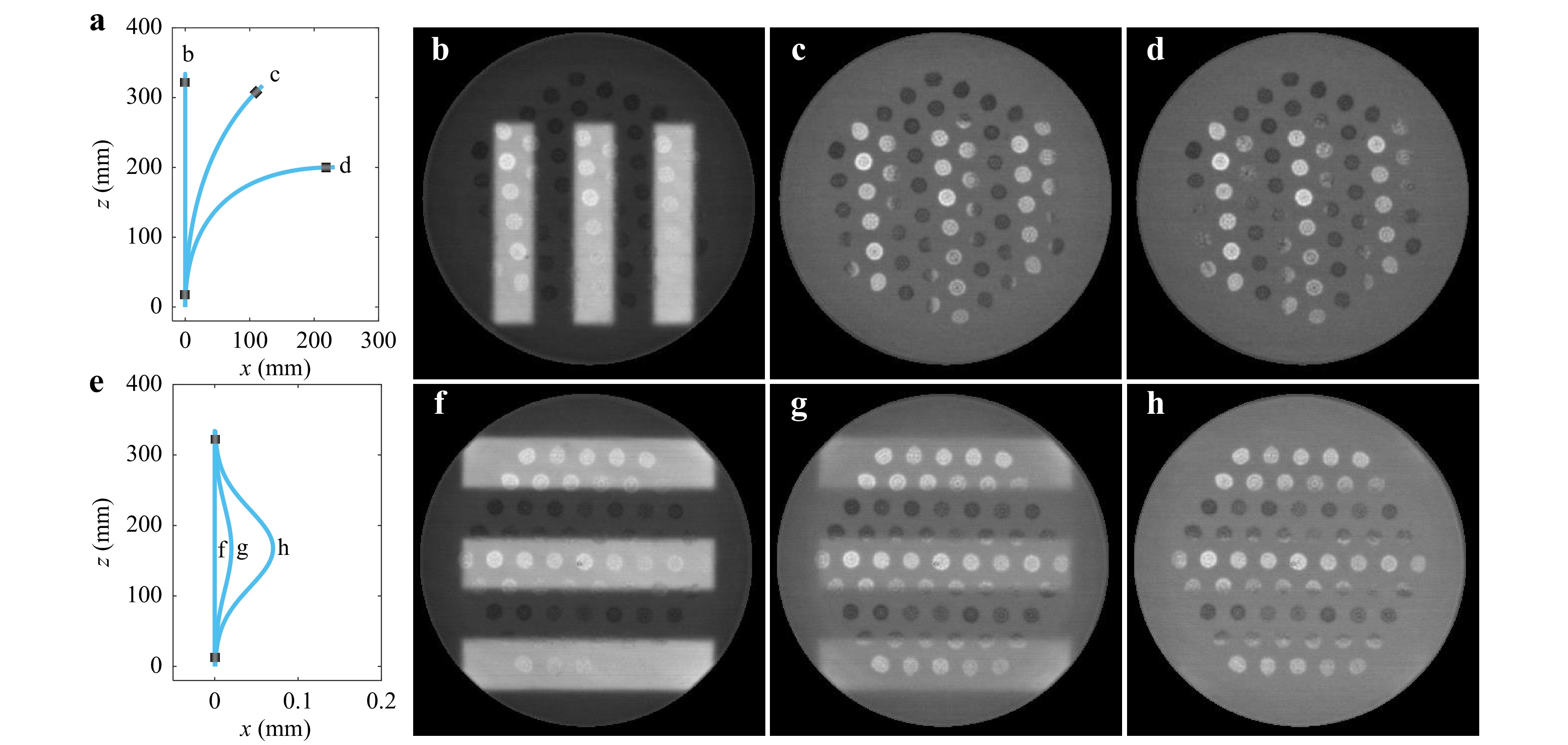
Fig. 2 a−d Imaging performance of the M3CF undergoing gradual fibre deformations. a Layouts of experimental fibre contortions. b−d Images obtained at different layouts as denoted in a. e−h Imaging performance of the M3CF under minor fibre deformations. e Layouts of experimental fibre contortions. f−h Images obtained at different layouts as denoted in e.
An additional bending test was designed to observe practical boundaries for applying holographic endoscopy through the developed probe. This new setting involves the displacement of the distal end of the fibre probe towards its proximal end using a linear translation stage, as depicted in Fig. 2e. Precision control over fibre deformation in this scheme allowed observing the degradation process of imaging quality, presented in Fig. 2f−h (performed at element 6 of group 3), from partially diminished contrast to complete loss of recognition similar to the previous experiment.
As expected, the performance within the pulp area is highly susceptible to fibre deformation, which limits utilising high-resolution imaging modality to a nearly rigid configuration suitable for neuroimaging applications only in immobilised animal models. In contrast, the corelets provide a low resolution but stable imaging performance even under significant bending deformations, acting like a fibre bundle. Another aspect worth mentioning in the scope of the proposed application of imaging-assisted implantation is sensitivity to local temperature changes. During a feasibility check, about 20 mm of the fibre tip was gradually heated up to 18°C above room temperature. No significant loss of imaging performance has been observed throughout the whole interval.
-
The experimental setup geometry, introduced in the methods section and utilised for holographic endoscopy imaging, allows for generating diffraction-limited focal spots at any desired position across the proximal fibre facet. With a digital micromirror device (DMD) placed in a far-field plane to the input fibre facet, the effective coupling NA can be controlled by constraining the area of the displayed DMD patterns within an appropriately sized circular aperture. Therefore, without modifying the experimental setup (shown in Materials and methods section), all 61 corelets can be addressed at will by projecting corresponding holograms on the DMD, as conceptually illustrated in Fig. 3a. Limiting the NA to 0.1 ensures light signals are spatially confined within the targeted corelets, thereby maintaining the light transport through the M3CF in the fibre bundle regime. To evaluate the cross-talk between corelets, we recorded high dynamic range images of the output fibre facet while coupling light to individual corelets, one at a time. The confusion matrices (cross-talk maps) were compiled from images of the distal M3CF facet. Two examples of such matrices are shown in Fig. 3c and d for the fibre under different bending conditions. As an integrated measure for spatial confinement of light, we use the average fraction of the power confined in the desired corelet with respect to the overall power delivered through the whole waveguide. This metric is plotted in Fig. 3e for different bending layouts. It is noteworthy that a portion of stray signal can appear in the neighbouring cores already at the coupling stage due to significant aberration in the system, in our case, caused mainly by the inherent curvature of the DMD, which has been utilised as a spatial modulator. A wavefront correction algorithm34 has been applied to counteract the aberration, thus facilitating an effective light coupling to the corelets and improved light confinement to the desired corelets at the fibre output, as shown in Fig. 3e. Overall, the measurements indicate a negligible influence of the corelets decoupling with the fibre at different layouts. Finally, we utilised a single combined hologram for coupling of signal to three corelets simultaneously. The resulting output, presented in Fig. 3b, confirms the ability to reach multiple regions of interest at once.
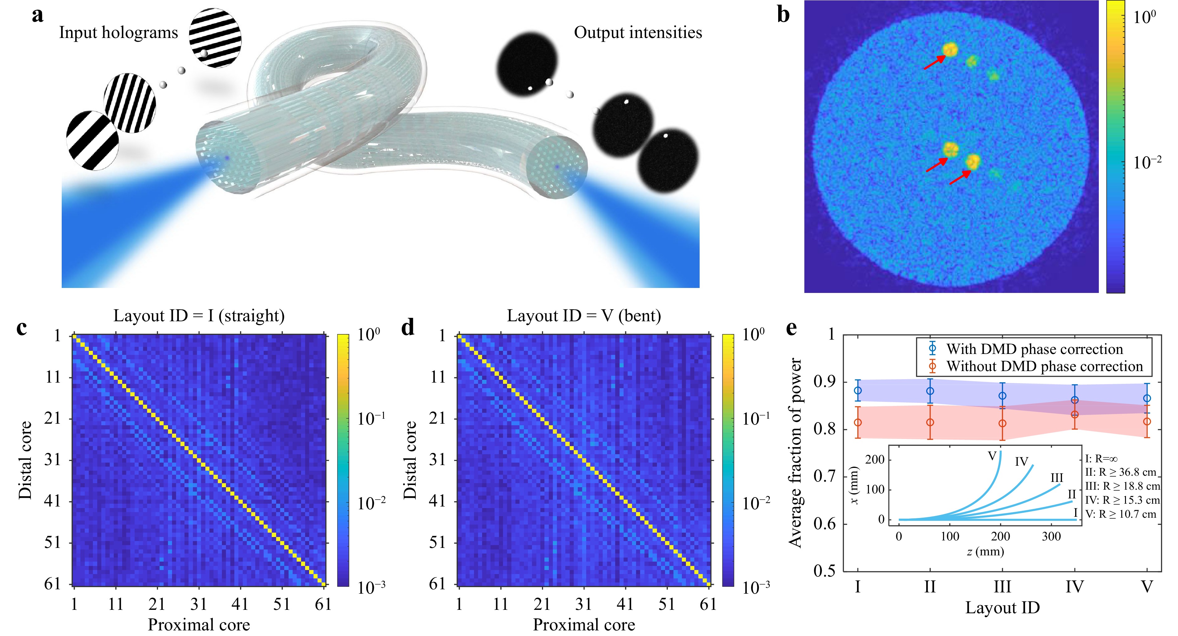
Fig. 3 Cross-talk assessment of the M3CF. a Illustration of the experimental concept. Addressing individual corelets is performed via displaying corresponding grating patterns on the DMD, placed in a far-field plane of the proximal fibre facet. b Image of the distal facet of the fibre, while three corelets (marked with red arrow) are simultaneously addressed with a single DMD pattern. c, d Confusion matrices, representing inter-core cross-talk, for both straight c and significantly bent d fibre layouts. e Averaged fraction of power preserved in the addressed corelets at various fibre bending positions. An experiment was performed with and without active correction of aberrations inherent to DMD. The inset depicts experimental fibre layouts for different bending positions and corresponding bending radii.
To summarise the independent validations of the multimode and fibre-bundle operating regimes, we performed a demonstration to exemplify the proposed applicational scenario involving both the modes mentioned above. A coverslip with a complex arrangement of 6 µm in diameter green fluorescent particles was placed at the focal plane of the calibrated, ready-to-image holographic endoscope equipped with an M3CF probe. At the first stage, while the fibre probe remains static in its initial precalibrated position, a high-resolution imaging session allowed navigation across the coverslip to select a region of interest with complex and dense distribution of the beads presented in Fig. 4a. Based on this high-resolution recording and known corelets layouts, a predicted low-resolution image, shown in Fig. 4b, was acquired as a reference for the following tests. Once navigation is done and the object of interest is in the field of view, the system can be switched to the fibre-bundle regime. Consequent display of 61 DMD patterns, pre-selected to efficiently couple light in the corelets, allowed to probe every core individually (Fig. 4e for scanning order) and record the fluorescent response via a photomultiplier tube. For clarity of comparison, the recorded intensities were mapped to the corelet layout of the probe. We demonstrated the fibre-bundle regime while bending and twisting the M3CF probe under test simply by hand, roughly mimicking deformations expected in field experiments. Records of the detected intensities (Fig. 4f) for static and dynamically deformed fibres carry the same set of features and show a close match in magnitude. The normalised intensities mapped in Fig. 4c, d for both instances are visually indistinguishable.
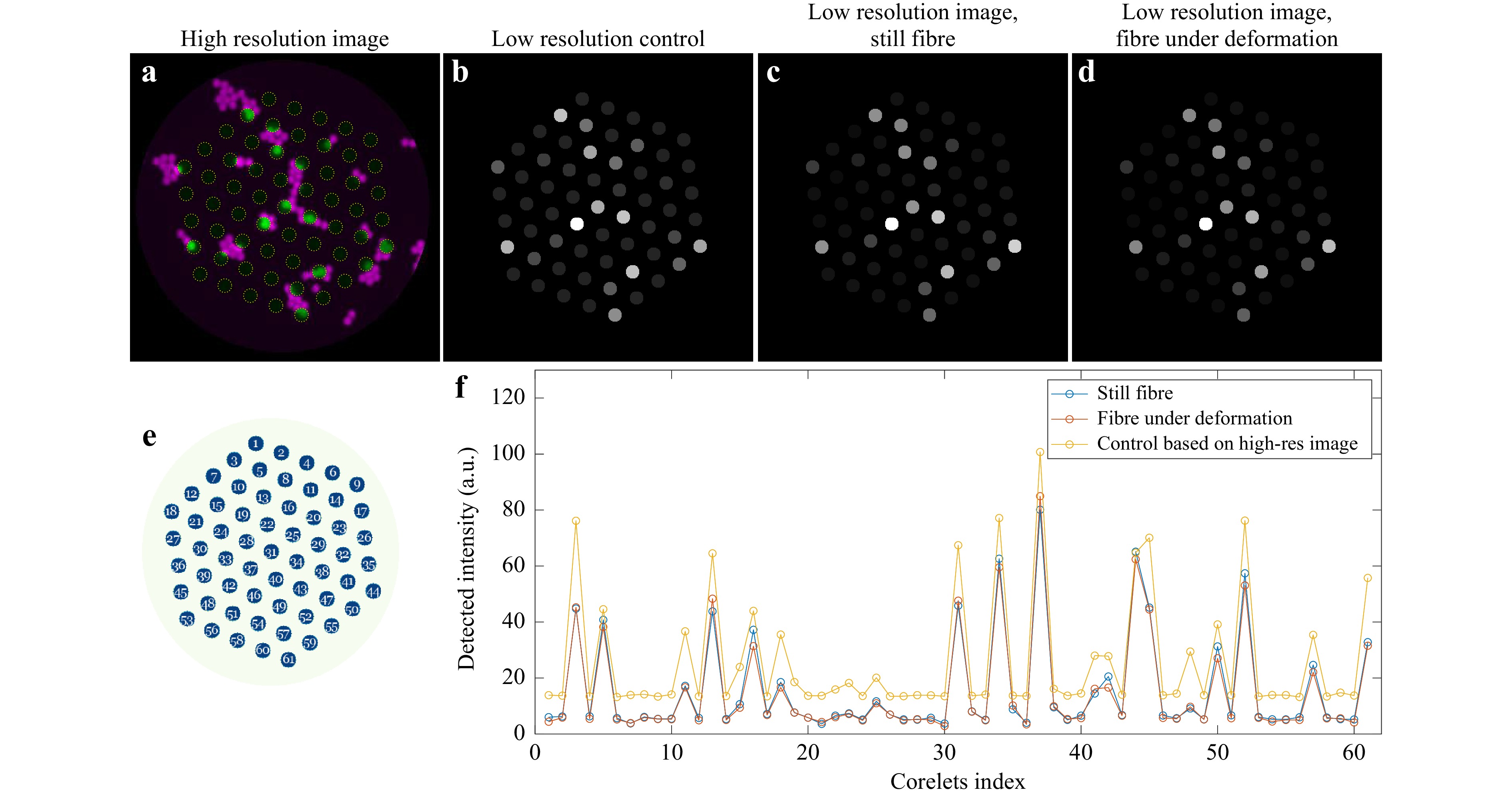
Fig. 4 Demonstration of application scenario. a High-resolution image of flusorescent beads obtained in the multimode fibre regime. Cyan colour corresponds to regions of the pulp, green highlights the regions of the corelets. b Predicted fluorescence response in fibre-bundle regime (probing corelets), obtained from the high-resolution image in a. c, d Fluorescent response obtained by probing individual corelets in both initial, pre-calibrated and pronouncedly deformed (bend+twist) positions correspondingly. e Distal fibre corelets layout with numbers representing scanning order. f Recordings obtained via sequential scan across the corelets for initial (corresponding to c), deformed d positions, as well as for the predicted result based on the high-resolution recording.
-
This work demonstrates a fibre probe designed specifically for imaging-assisted deep-brain activity monitoring and optogenetics. The proposed design relies on a structure with a cascaded refractive index profile. Together with the cladding, the core forms a highly multimode waveguide. At the same time, it maintains independent light guidance within 61 equidistantly spaced corelets. This arrangement allowed performing raster-scanning imaging at the distal fibre facet with an optical resolution of about 2 µm across the 230 µm field of view when employed in a holographic endoscope system. The embedded multicore structure demonstrated robust optical access, which remains stable even under severe bending deformation when holographic imaging performance is significantly compromised. The optical scheme with a DMD placed in a far-field plane to the proximal fibre facet was arranged for the laser power to be efficiently redistributed between the corelets, enabling high-speed sequential or even simultaneous channelling of light via multiple corelets at will.
These operating modes delivered through a single minimally invasive probe can offer synergetic benefits in animal studies, allowing high-resolution visual guidance for precise probe implantation and initial acute observations, followed by chronic monitoring and stimulation of the pre-selected regions of interest in freely moving animals.
Although integrated into a single probe, it is important to highlight that large multimode core and multicore imaging structures can be utilised independently. The infused corelets do not obstruct the field of view or compromise the imaging quality when performing holographic endoscopy. At the same time, light coupled to the small cores remains spatially confined when propagating through the fibre.
Such direct access to the sample plane could allow spatially resolved photostimulation without the necessity of wavefront shaping and highly coherent laser sources. Moreover, operational wavelengths of optogenetic tools for light-activated control and reporting neuronal activity are often detuned from each other, enabling their simultaneous application. As a result, a budget-friendly set of an LED array, relay optics, and dichroic mirrors could extend a holographic endoscopy system for deep-brain imaging with optogenetics modality. Moreover, once implantation is done, the comprehensive wavefront shaping system can be replaced with such LED-based module, not only avoiding permanent need in an expensive piece of equipment, but also enabling a switch to any desired excitation wavelength for following chronic experiments.
We envision that the design of highly versatile yet practical M3CF probes presented in this work will become an enabling attribute giving the relevant neuroscience community access to the deepest brain regions while being equipped with the most powerful portfolio of neurophotonics tools for studying neuronal activity.
-
The M3CF fibre was fabricated by using the stack-and-draw technology. The preform design and stack are shown in Fig. 5a, b. The primary preform was assembled in a four ring hexagonal stack of Germanium doped rods. The corelet rods having an outer diameter of 1 mm are prepared by using modified chemical vapor deposition (MCVD) preforms with 24 doped core layers of 2.5 mol% GeO2 and a core-clad-ratio of 0.5. The designed NA of the corelet rods is 0.1. The MCVD substrate tube material and the container tube material (outer diameter 11.2 mm; inner diameter 9.5 mm) was high purity silica Heraeus F300. For the minimization of geometrical deformations, the volume between the 61 hexagonally arranged corelet rods and the container tube was filled with Heraeus F300 silica rods of diameter 0.7 mm and 0.47 mm respectively. The resulting preform was overcladded with a depressed index silica tube (outer diameter 14 mm; inner diameter 12 mm). The material of the overcladding tube was Heraeus F520 (∆n −5 × 10⁻³, 1 mol% SiF4). The designed NA for the core / cladding interface was 0.1.
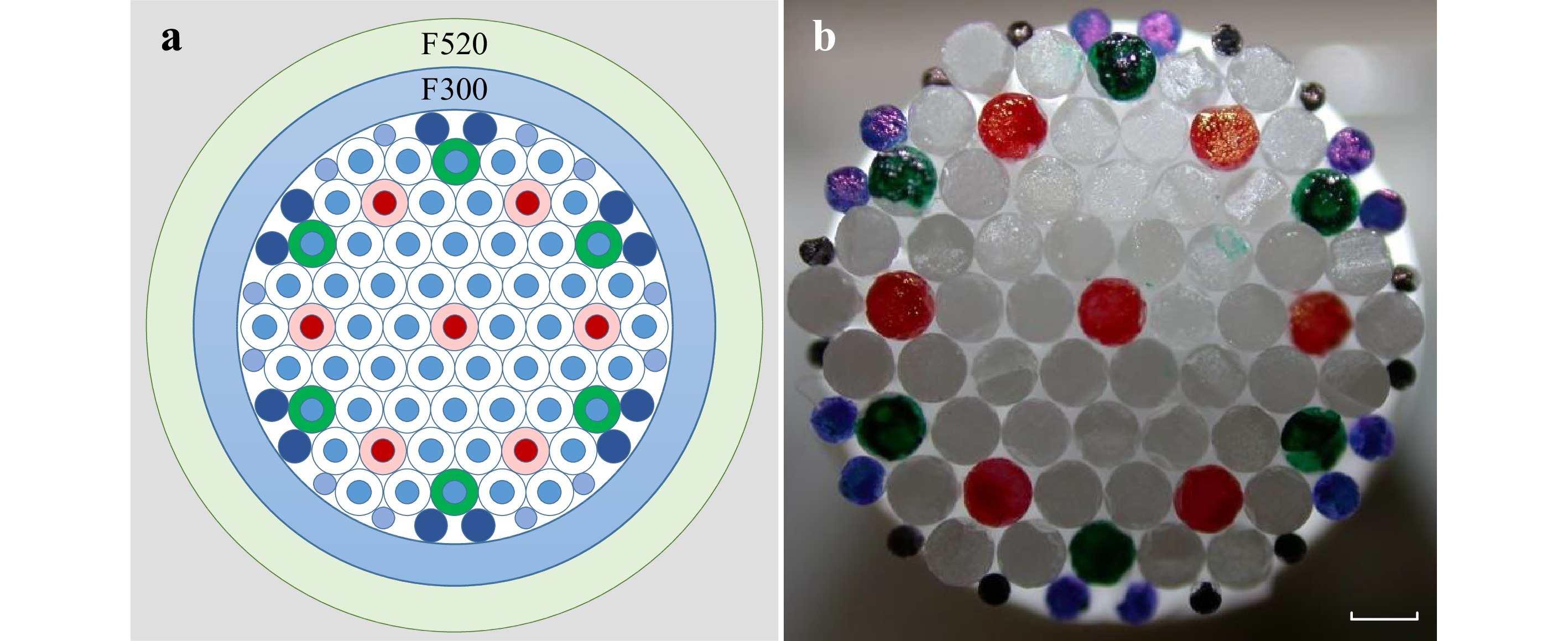
Fig. 5 Schematic diagram of M3CF preform design. The primary preform was assembled in a four ring hexagonal stack of Germanium doped rods with a total of 61 elements. The primary jacket tube was high purity silica Heraeus F300. Silica rods (Heraeus F300) with two different diameters were filled between hexagonal arranged rods and the primary overcladding tube. A secondary tube Heraeus F520 was applied as outer cladding. b A photograph of preform stacking as described in a. The colours labelled on the glass rods are used to ensure we have the correct structure arrangement during the stacking procedure.
Scale bar indicates length of 1 mm.The M3CF fibre was fabricated from the above described preform inside the in-house fibre drawing tower. The preform was evacuated during the drawing process to sinter any remaining-interspace volume. The drawing process was conducted at the speed of 6.5 m/min, leading to M3CF of 278 µm in diameter. The germanium doped corelets were manufactured with average size of 11.3 µm in diameter. For protecting the fibre from environmental impacts, a single layer coating of UV curing acrylate was applied to the M3CF, which has been removed during the light-transport experiments.
-
The experimental setup is illustrated in Fig. 6. A single frequency continuous wave laser at wavelength of 488 nm was used in all experiments. Linearly polarised light beam from the laser is expanded by a telescope formed from two achromatic lenses L1 and L2. The light beam is separated by a polarizing beam splitter PBS to a signal and a reference beams. A half wave plate HW1 and an optical isolator ISO are added to control the overall power of the two beams. A half wave plate HW2 is inserted to alter the power ratio between the two beams. These two beams are further coupled into single mode polarisation maintaining fibres PMF1 and PMF2 via achromatic lenses L3 and L8, respectively. Half wave plates HW3 and HW5 align the two beams with either a fast or slow axis of the polarization-maintaining fibres. A half wave plate HW4, together with a linear polarizer LP are applied to ensure a linearly polarized light to be coupled into the M3CF fibre. In the signal path, the beam is collimated by an achromatic lens L4 to overfill the active area of a digital micromirror device DMD. The DMD is installed in an off-axis regime at an angle of 24° with respect to the incident light beam. The farfield of the first-order diffracted signal formed by holograms applied on the DMD is relayed by lenses L5, L6 and L7 to the proximal end of M3CF. The focal lengths of L5, L6 and L7 are carefully selected to adapt to the NA of M3CF. An iris is set at the Fourier plane of L5 for separating the first diffraction order from other contributions. Microscope objective OBJ and tube lens L10 image the distal end of fibre facet onto a CMOS camera. In the reference path, a lens L9 collimates the beam exiting from PMF2. A half wave plate HW6 is chosen to adjust the linear polarization angle of the reference beam for maximizing the contrast of the interference signal. A non-polarizing beam splitter BS is placed to combine the signal and the reference beams.
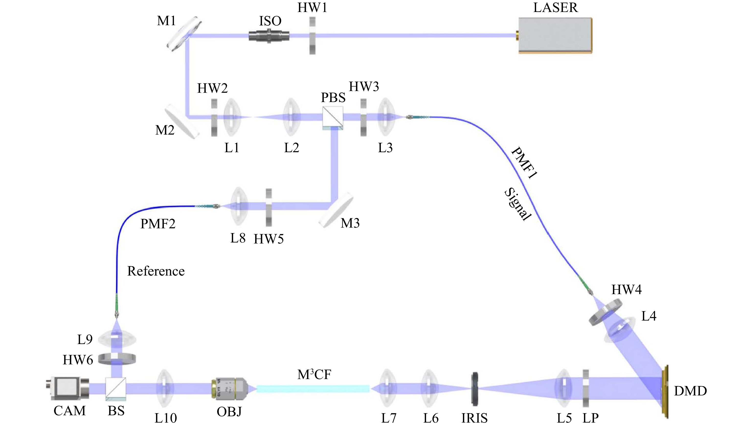
Fig. 6 Scheme of multicore fibre-based imaging setup. LASER: Coherent Sapphire SF 488; HW1-HW6: Thorlabs WPH05M-488; ISO: Thorlabs IO-3-488-HP; M1-M3: Thorlabs BB1-E02; L1: Thorlabs AC254-050-A-ML; L2, L4: Thorlabs AC254-100-A-ML; L3, L7, L8, L9: Thorlabs A240TM-A; L5: Thorlabs AC254-200-A-ML; L6: Thorlabs AC254-200-A-ML; L10: Thorlabs AC254-125-A-ML;PMF1: Thorlabs P5-488PM-FC-1; PMF2: Thorlabs P5-488PM-FC-2; DMD: ViALUX V7001; LP: Thorlabs LPVISE100-A; IRIS: Thorlabs SM2D25D; OBJ: Olympus Plan Achromat 10X NA 0.25; PBS: Thorlabs PBS101; BS: Thorlabs BS010; CAM: Basler acA640-750um. Beam-blocks and Neutral-density filters are not shown in the scheme.
We adopt the transmission matrix (TM) algorithm for controlling the light transport through the M3CF20,35 and image acquisition. The TM represents a linear relationship between input and output optical modes of a given medium, and with its availability, one can synthesize any desired output field despite the medium's complexity. The DMD (chip size: 1024 × 768 pixels) is a programmable component employed in the system for light beam shaping through the fibre. Although the DMD is a binary amplitude light modulator, it enables providing phase modulation when it is applied in the off-axis regime15. The M3CF supports approximately 12490 modes at the wavelength of 488 nm. The input modes are chosen as a square grid of 191 × 191 diffraction-limited foci. Prior to the TM acquisition, a primary alignment is performed by integrating the output field received from the camera for each individual input mode. This step is to ensure that the fibre is correctly positioned and oriented with respect to the imaging system and it eliminates any input modes falling outside the spatial constraints of the fibre, reducing their number to ~26 000. At the distal end of the fibre, the output modes are analogously occupying a square grid of 352 × 352 focal points with an interval of ~0.7 µm to fully cover and significantly oversample the entire M3CF core during acquisition. Further, during image acquisition, the number of output modes is analogously reduced to those ~87000 falling into the circular area of the core.
-
The authors acknowledge the support from the European Research Council (724530), Ministry of Education, Youth and Sports (CZ.02.1.01/0.0/15_003/0000476), Thüringer Ministerium für Wirtschaft, the European Regional Development Fund (CZ.02.1.01/0.0/15_003/0000476), Wissenschaft und Digitale Gesellschaft, the Federal Ministry of Education and Research, Germany (BMBF), and the Thüringer Aufbaubank. The authors would like to acknowledge Dr. Jörg Bierlich, Claudia Aichele, Anne Matthes for preform preparation and fibre drawing; Anka Schwuchow for taking microscope photographs for Fig. 1a; Dr. Dirk E. Boonzajer Flaes for fruitful discussions. The multicore fibre used in this work was drawn at fibre drawing facility at Leibniz Institute of Photonic Technology. The USAF 1951 target used in all imaging experiments was custom-made by the Electron Beam Lithography group of the Institute of Scientific Instruments of the CAS, v.v.i.
Hybrid multimode - multicore fibre based holographic endoscope for deep-tissue neurophotonics
-
Yang Du1,
 ,
, - Sergey Turtaev1,
- Ivo T Leite1,
- Adrian Lorenz1,
- Jens Kobelke1,
- Katrin Wondraczek1,
-
Tomáš Čižmár1, 2, 3, ,
- Light: Advanced Manufacturing 3, Article number: (2022)
- Received: 31 August 2021
- Revised: 06 April 2022
- Accepted: 21 April 2022 Published online: 21 June 2022
doi: https://doi.org/10.37188/lam.2022.029
Abstract: In-vivo microendoscopy in animal models became a groundbreaking technique in neuroscience that rapidly expands our understanding of the brain. Emerging hair-thin endoscopes based on multimode fibres are now opening up the prospect of ultra-minimally invasive neuroimaging of deeply located brain structures. Complementing these advancements with methods of functional imaging and optogenetics, as well as extending its applicability to awake and motile animals constitute the most pressing challenges for this technology. Here we demonstrate a novel fibre design capable of both, high-resolution imaging in immobilised animals and bending-resilient optical addressing of neurons in motile animals. The optimised refractive index profile and the probe structure allowed reaching a spatial resolution of 2 μm across a 230 μm field of view for the initial layout of the fibre. Simultaneously, the fibre exhibits negligible cross-talk between individual inner-cores during fibre deformation. This work provides a technological solution for imaging-assisted spatially selective photo-activation and activity monitoring in awake and freely moving animal models.
Research Summary
Hybrid multimode – multicore fibre: flexible probe for deep tissue application
In-vivo microendoscopy in animal models became a groundbreaking technique in neuroscience that rapidly expands our understanding of the brain. Emerging hair-thin endoscopes based on multimode fibres are now opening up the prospect of ultra-minimally invasive neuroimaging of deeply located brain structures. Yang Du, Tomáš Čižmár and colleagues from Germany’s Leibniz Institute of Photonic Technology demonstrates a comprehensive fibre probe design extending the applicability of usually bending intolerant holographic endoscopes towards flexible implementations, highly desired for deep-brain activity recording and optogenetics. The proposed design relies on a multimode-multicore structure with a cascaded refractive index profile, which allows for raster-scanning imaging at the fibre distal facet with a micron-scale optical resolution. At the same time the embedded multicore structure exhibited robust optical access, which remains stable even despite severe bending deformation.

Rights and permissions
Open Access This article is licensed under a Creative Commons Attribution 4.0 International License, which permits use, sharing, adaptation, distribution and reproduction in any medium or format, as long as you give appropriate credit to the original author(s) and the source, provide a link to the Creative Commons license, and indicate if changes were made. The images or other third party material in this article are included in the article′s Creative Commons license, unless indicated otherwise in a credit line to the material. If material is not included in the article′s Creative Commons license and your intended use is not permitted by statutory regulation or exceeds the permitted use, you will need to obtain permission directly from the copyright holder. To view a copy of this license, visit http://creativecommons.org/licenses/by/4.0/.

 DownLoad: